Transcription
Gas Pressure RegulatorRMG 402Operation and Maintenance,Spare PartsServing the Gas Industry - WORLDWIDE402.20edition 01/2000
Content:1.1.11.21.2.1General.Instructed persons .Security instructions.Risk characteristics, 23.2.33.33.43.53.6Special Operating Instructions: Gas Pressure Regulator RMG 402.Start-up.Shut-down.S.04S.04S.04Special Maintenance Operations: Gas Pressure Regulator RMG 402.Main Valve.Pilot RMG 620.Double diaphragm system.Pressure compensating element.Lubricants.Torques.Lubricant charts.Screw seals.Examples of different pilot combinations with main body e Parts Drawings.RMG 402 DN 25.RMG 402 DN 50, DN 50/100.RMG 402 DN 80, DN 80/150, DN 100, DN 100/200.RMG 402 Noise reduction.RMG 402 Pilot 630 / 640.RMG 402 SAV Remote indication for RMG 673 / 674.RMG 402 Pilot 620 DN 25, DN 50, DN 50/100.RMG 402 Pilot 620 DN 80, DN 80/150, DN 100, DN 100/200.RMG 402 Additional parts for RMG 620 DN 25.RMG 402 Additional parts for RMG 620 DN 50.RMG 402 Start-up valve for RMG 630/640 DN 25, 50.RMG 402 Start-up valve DNE 80 and DNE 100 with pilot RMG 620.RMG 402 Start-up valve for RMG 630/640 DN 80, .9.15.9.25.105.115.125.135.14Spare Parts Lists.RMG 402 DN 25.RMG 402 DN 50, DN 50/100.RMG 402 DN 80, DN 80/150.RMG 402 DN 100, DN 100/200.RMG 402 Pilot 620 DN 25, DN 50, DN 50/100.RMG 402 Pilot 620 DN 80, DN 80/150, DN 100, DN 100/200.Type with RMG 630/640 DN 25 and DNE 50 .RMG 402 with noise reduction .DNE 25 and DNE 50.DNE 80 and DNE 100.RMG 402 SAV Remote indication for SAV RMG 720/721 from DNE 50.Type without SAV RMG 72/721 from DNE 50.Type without SAV Remote indication from DNE 50 with SAV 720/721.RMG 402 Accessories for RMG 620 DN 25.RMG 402 Accessories for RMG 620 DN 50.RMG 402 Start-up valve for RMG 630/640 DN 25, 50.RMG 402 Start-up valve for RMG 620 DN 80, 100.RMG 402 Start-up valve RMG 630/640 DN 80, 6.26.2.16.2.26.2.36.2.4Special Operation and Maintenance Instructions - SAV RMG System 721.Switching device RMG 721.Opening of the safety shut-off valve SAV with new opening mechanism.Dismantling of the switch bearing and of the ball bearing in the switching device.Priming adjustment of manual release device onto the switch gear.Adjustment of the release device.Pneumatic release.Pneumatic direct release.Electromagnetic release by current failure.Electromagnetic release by current .1Spare Parts Drawings SAV RMG System 721. S.36Switch gear RMG 721 DN 50, DN 80, DN 100.with latch/levering opening mechanism. S.368.8.1Spare Parts Lists SAV RMG System 721. S.37Switch gear RMG 721 DN 50, DN 80, DN 100.with latch/levering opening mechanism. S.37402.20 p.02
1. GeneralIn addition to this leaflet 402.20 concerning "Operation and Maintenance, Spare Parts" of the regulator RMG 402, the brochure402.00 gives full information about all relevant technical data, description of function, the available different versions,and the dimensions.Due to the special design and operation of the RMG 402, we recommend to study and observe the special instructions withinthese leaflets as well:Pilot:RMG 630/640General DescriptionOperation and Maintenance, Spare Parts630.00630.20SAV:RMG 720 / 721General DescriptionOperation and Maintenance, Spare PartsControl Devices K1a, K2aControl Devices K4, K5, K6Control Devices K10a, K12, K13, K16, K17402.00General DescriptionOperation and Maintenance, Spare Parts905.00905.20RMG 905Filter:673.20674.20672.20The RMG brochure "General operating instructions for gas pressure regulators and safety devices" will be useful to fit the regulator into the line, put it into service and find faults that might disturb its operation. Please also check if the construction, set-up,supervision and maintenance of gas pressure regulating stations may be subject to special national regulations. These technicalrules should be observed strictly (Within Germany observe the DVGW worksheets G 490, G 491, G 495).The frequency of periodical maintenance of gas pressure regulators and other components of the regulating line is stronglydependant on the prevailing service conditions, the type and composition of the gaseous medium, the ambient temperature andon dust and dirt withing the pipe system. We therefore abstain from imposing any fixed intervals and would rather advise testingout the necessary maintenance intervals, starting with short gaps (i.e. quarter of a year) for maintenance disassembly, and thenincreasing the intervals to a maximum of 2 years, if no defects within the spare parts show up.For maintenance all parts are to be cleaned and subjected to a thorough visual inspection. Complete dismantling together withvisual inspection should not be omitted when the course of operation or performance tests have shown lack of accuracy.Particular care should be given to the checking of sealings and diaphragms, as well as the closing spring and all movable parts.Damaged parts should be replaced by new ones.The item numbers referred to in the maintenance instructions are identical with those of the spare parts drawings and spareparts lists.Note!We recommend to keep all parts marked "EV" in stock for maintenance availability.1.1 Appointed workmenExpertsThanks to his technical training, his practical work and his experience, the expert has sufficient knowledge in the field of maintaining complete gas facilities as well as the single devices with their constructional elements and sub-groups. He must beacquainted with the purpose and the tasks of gas pressure regulating facilities, with the relevant laws, guidelines and generaltechnical rules, and must also be capable of deciding and acting on his own.Qualified employeeThe qualified employee must posess special, proven knowledge for the certain task he is about to perform. He is acquaintedwith the general rules and regulations, and it is guaranteed that he can carry out tasks correctly when ordered to do so.Instructed personA person trained to accomplish simple tasks.Tasks and workmeninstructed personqualified employeeexpertVisual checksInspectionFunctional testsMaintenance / repairsPutting into operation / re-startingOperation using by-pass linesadditional2nd personrequired402.20 p.03
1.2 Security Instructions1.2.1 Risk characteristics, generalSecurity instructions are marked in the operating instructions by the following signal words or symbols :DesignationUsed by:! Warning !Risk of injury to personnel! Caution!Risk of damaging equipment andenvironmentNote!2.Additional information or requirementsSpecial Operating Instructions2.1 Start-up: Close the outlet gate valve Release completely the setpoint springs of the pilots RMG 620, 630, 640 of the loadlimiting stage and of the auxiliary pressure stage (only valid for the RMG pilot 630) by turningthe setpoint adjusting screw (218) counter-clockwise.(The complete releasing of the setpoint screws is at least recommendable for start-up)Note!! Caution!Note! Open the start-up valve. The existing start-up valve assures a pressure compensationon the expansion diaphragm (6, 107) Pressurize slowly. The start-up valve (107, 125, 135) must be absolutely re-closed. Adjust the setpoint of the load limiting unit of pilot RMG 630 to approximimately 5 barabove the outlet pressure (pa ).! Caution! Open the outlet gate valve slowly. Increase slowly the setpoint value with the adjusting screw (218) until the device takes overthe gas supply and the outlet pressure pas wanted is adjusted.2.2 Shut-down: Close the outlet gate valveor Turn the setpoint screw slowly counter-clockwise (release)402.20 p. 4
3.Special Maintenance Operations3.1Main Valve Expansion diaphragm (6, 107)The expansion diaphragm must be put into the corresponding seat of the main valve(11, 52, 113) without distorsions. A diaphragm having a too big outer diameter must bereplaced. Noise reduction (180)When mounting the metal foam ring (180), please see that the working surface on the ringshows downwards (showing to the outlet surface of the seat of the main valve) Foamed disc / foamed ring (102, 105 ) from the pipe size DN 80The damping elements (102, 105) must be replaced for each maintenance.The damping disc situated on the diaphragm plate must be fixed to the part (104) withbounding agent (Loctite 454 ).3.2Pilot RMG 6203.2.1 Double diaphragm systemBy releasing the screw connection (207) between the parts (208) and (209) the doublediaphragm system can be dismantled and visually controlled.Diphragms (210) must be inspected on porous places or on the detachment of the rubbercoating. For the dismantlement of the screws (212) are released from the stay bolts (216).If damages are noticed on the piston sealing (241), the bolts must be replaced.Unscrew the pistons (241 premounted part) of the amplifying valve out of the pistonguide (240) by releasing the hexagonal nut (241).Note!The sealing edge of the orifice (239) of the amplifying valve should not show any mechanicaldamages.To mount each part of the double diaphragm system, please care about the followingremarks:Note!! Warning- Premounted piston (241)The piston is mounted with a suspension spring and provided with a corresponding distancedimension for the amplifying valve.If the pilot was maintained, the piston must be replaced (higher closingpressure).- Diaphragm fixing ( 211, 214)The rounded-off side on the diaphragm plates (211, 214) must show to the diaphragm (210).3.2.2 Pressure compensating element (303) from DN 80Control the easy-running of the pressure compensating pin or grease it with silicone grease.3.2.3 LubricantsAll parts must be greased according to the lubricants lists (see lubricants charts on the nextpage).402.20 p.05
3.3 TorquestorqueMA in Nm3.4screwpos. no.DN 25[Nm]DN 50[Nm]DN 80[Nm]DN 7303030302126666 Lubricantselement (grease slightly)lubricantRMG-part no.silicone greasecan 1,0 kg 00 027 079tube 0,1 kg 00 027 081high pressure grease00 027 058all o-ringsmounting swelling of expansiondiaphragm (6, 107)switching balls (510)ball bearing intermediary spaces(529)all fixing screwsand all pipe connections3.5 Screw sealselementcylinder screw (1, 103)**) is to be found in specialized stores402.20 p.06meansLOCTITE**)Type 221
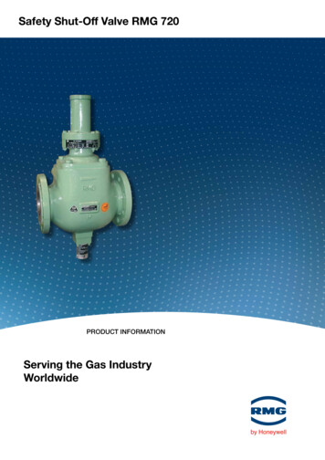
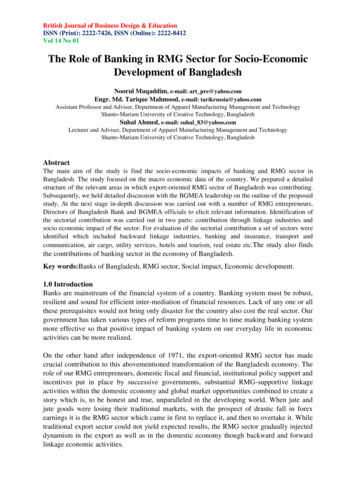
3.6 Examples of different pilot combinations without or with outlet expansiona) RMG 402 without outlet expansion, f.i. with pilot RMG 620 and SAV-unit RMG 720 / K4setpoint adjusterthrottlevent lineclosing springdischarge valve(only for pipe size DN 80)main and expansiondiaphragmreturn lineslotted platemeasuring t linesetpoint springsswitching valveRMG 919setpoint adjusterb) RMG 402 with outlet expansion, f.i. with pilot RMG 630a and SAV-unit RMG 721 / K12double diaphragmsystemPilotvent linemeasuring linemeasuring diaphragmreturn-linethrottlesetpoint springstart-up valveload limiting stagefine filtercontrol stageloading pressure areaclosing springmain and expansiondiaphragmslotted plateMain ValveSAV closing springSAV-measuring lineSAV switching deviceSAV vent lineswitching valve RMG 919Safety Shut-off Valve(SAV)actuator ball releasemechanismSAV-setpoint springsopening latch402.20 p.07
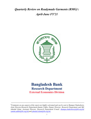
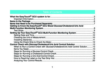
4. Spare Parts Drawings4.1 Spare Parts Drawing RMG 402 DN 25from serial number 95 10 157 88see spare parts list p. 21RMG 620 see page 12123412(EV)5136(EV)78(EV)910(EV)141115SAV K1a, K2asee 673.20type with SAVNote!402.20 p.08type without SAVParts marked by EV are to be kept in stock for maintenance
4.2 Spare Parts Drawing RMG 402 DNE 50Type from serial number.: 95 10 157 88see spare parts list p. 22RMG 620see page 7SAV K4, K5, K6see 674.20typewith SAVNote!typewithout SAVParts marked by EV are to be kept in stock for maintenance402.20 p.09
4.3 Spare Parts Drawing RMG 402 DNE 80 to DNE 100(type marked DN 100/200)from serial number 95 041 4600see spare parts list p. 21, 22RMG 620see page 13SAV K4, K5, K6see 674.20type with V)118119120type without SAV124(EV)126125* (126 type without SAV)124(EV)* with SAV but without proximity switching deviceNote!402.20 p.10Parts marked by EV are to be kept in stock for maintenance
Spare Parts Drawing RMG 402 Sectional view4.4Type with noise reductionsee spare parts list p. 27180181Type with pilot RMG 630/6404.5see spare parts list p. 27182183184, 185186(EV) 187188Type with SAV RMG 720 and RMG 7214.6see spare parts list p. 28! Caution!The assembly of the proximityinitiator (192) for remote indicationof the SAV valve plate positionmay only be done if the SAV hasbeen closed completely190191192193194(EV)The rolling connection used upto 1997 has been replaced bya screw connection on thevalve rod of the SAV RMG 720Note!Parts marked by EV are to be kept in stock for maintenance402.20 p.11
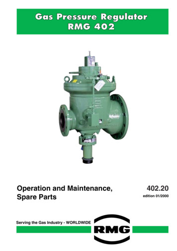
4.7 Spare Parts Drawing RMG 402 DN 25 to DNE 50 with pilot RMG 620see spare parts list p. 23, 24200218A201219202220203221, (EV)211221, 222212228229(EV)242A213 210 214 215(EV)202 216 217(EV)"X"238(EV)sectional view A - A239240241(EV)232(EV)233234235, 236237230231(EV)Note!402.20 p.12Parts marked by EV are to be kept in stock for maintenance
4.8 Spare Parts Drawing RMG 402 DNE 80 to DNE 100 with pilot RMG 620see spare parts list p. 25, 26218A200219201220202221, 222203223204224205(EV)225(EV)206207301208221, 222209301210(EV)225(EV)211212"X"300 210 214(EV)A202 216 217(EV)238(EV)239240sectional view A - 6231(EV)306305Note!Parts marked by EV are to be kept in stock for maintenance402.20 p.13
4.9 Type DN 25see spare parts list p. 29400,401 406402RMG 620see page 12RMG 905see 905.20403,404405SAV K1a, K2asee RMG 673.20Note!402.20 p.14Parts marked by EV are to be kept in stock for maintenance
4.10 Type DNE 50see spare parts list p. 29RMG 620see page 12410,411416412filter RMG 905see 905.20413,414415SAV K4, K5, K6see 674.20402.20 p.15
4.11 Type for DN 25 and DNE 50 with pilot RMG 630/640(marked DN 50/100)see spare parts list p. G 905see 905.20switching devicesee page 36402.20 p.16RMG 630 (RMG 640)see 630.20 (640.20)
4.12 Start-up valve DNE 80 and DNE 100 with pilot RMG 620see spare parts p. 30430431,432431,432435433filter RMG 905see 905.20434434433431/432434420.20 p.17
4.13 Start-up valve for DNE 80 and DNE 100 with pilot RMG 630/640see spare parts list p. 30440441442443,444447445443,444446447443,444447RMG 630 (RMG 640)see 630.20 (640.20)443,444448450443,444449RMG 905see 905.20SAV K4, K5, K6see 674.20402.20 p.18
5.Spare Parts Lists5.1pos.no.123456789101112131415Spare Parts List RMG 402 DN 25 from serial no. 951015788descriptioncylinder screwclosing springcapdiaphragm platecylinder screwdiaphragmexpansion piece:o-ringflow separatoro-ringcasing :pressure stage PN 16/25pressure stage ANSI 150sealing ringcylinder screwlocking platecylinder LMEVKGLMEVKGGGGGGGEVLMStLMStstock no.00 008 17710 024 05500 027 78610 021 48900 008 17410 011 30410 021 48800 021 07410 021 49300 020 5see drawing p. 8NoteParts marked EV are to be kept in stock for maintenanceSt. steelNSt. stainless steelFSt. spring steelNFSt. stainless spring steelGS. cast steelGGG. cast with nodular castLM. light metalGLM. light metal castGZn. zinc castMS. brassGMs. brass castCu. copperK. plastic material generalKG. rubber-like plastic materialKGT. plastic material sprayed with TeflonBz. bronzeKV. VitonGBz. bronze castKT. TeflonAlBz. aluminium bronzePGI. plexiglass402.20 p.19
5.2 Spare Parts List RMG 402 DNE 50 from serial no. 951015788pos.no.1234567891213descriptioncylinder screwclosing springcapdiaphragm platecylinder screwdiaphragmexpansion pieceo-ringcurrent separatorsealing ringcylinder screw5 0 o-ring5 1 disc5 2 casing: DN 50/50pressure stage PN16/25pressure stage ANSI 150casing:DN 50/50pressure stage PN 16/25/40pressure stage ANSI 150pressure stage ANSI 300casing : DN 50/100pressure stage PN 16pressure stage PN 25/40pressure stage ANSI 150pressure stage ANSI 3005 3 o-ring5 4 locking plate5 5 disc5 6 hexagon nut5 7 locking SEVKGLMEVStStStstock no.00 008 17710 024 05500 027 78610 021 48900 008 17410 011 30410 021 48800 021 07410 021 49300 018 80700 010 31800 020 75210 008 55910 021 49810 021 49910 023 23510 023 23710 023 6857858859246475113692376see drawing p. 9NoteParts marked by EV are to be kept in stock for maintenanceSt. steelNSt. stainless steelFSt. spring steelNFSt. stainless spring steelGS. cast steelGGG. cast with nodular castLM. light metal402.20 p.20GLM. light metal castGZn. zinc castMS. brassGMs.brass castBz. bronzeGBz. bronze castAlBz. aluminium bronzeCu. copperK. plastic material generalKG. rubber-like plastic materialKGT. plastic material sprayed with TeflonKV. VitonKT. TeflonPGI. plexiglass
5.3 Spare Parts List RMG 402 DN 80, DN 80/150 from serial no. ptionclosing springringcylinder screwdiaphragm plateringcylinder screwdiaphragmexpansion piecesealing ringo-ringcylinder screwcurrent separatorcasing: DN 80pressure stage PN 16/25pressure stage ANSI 150pressure stage PN 16pressure stage PN 25/40pressure stage ANSI 150pressure stage ANSI 300casing: DN 80/150pressure stage PN 16pressure stage PN 25/40pressure stage ANSI 150pressure stage ANSI 300o-ringdiscclosing plateo-ringdischexagon nutlocking screwnozzlecompression jointcap nutsealing ringlocking screw (with bore)locking screw (without SGSGSGSGSGSEVKVStLMEVKGStStStStStStEVLMStStstock no.10 023 24510 024 05600 010 62010 024 11110 024 05700 008 17410 011 30510 021 81200 018 81800 021 07500 010 32010 011 2559675427114120212154903802694474381see drawing p. 10NoteParts marked by EV are to be kept in stock for maintenanceSt. steelNSt. stainless steelFSt. spring steelNFSt. stainless spring steelGS. cast steelGGG. cast with nodular castLM. light metalGLM. light metal castGZn. zinc castMS. brassGMs.brass castCu. copperK. plastic material generalKG. rubber-like plastic materialKGT. plastic material sprayed with TeflonBz. bronzeKV. VitonGBz. bronze castKT. TeflonAlBz. aluminium bronzePGI. plexiglass402.20 p.21
5.4 Spare Parts List RMG 402 DN100, DN100/200 from serial number ptionclosing springringcylinder screwdiaphragm plateringcylinder screwdiaphragmexpansion piecesealing ringo-ringcylinder screwcurrent separatorcasing: DN 100pressure stage PN 16pressure stage PN 25pressure stage ANSI 150pressure stage PN 16pressure stage PN 25/40pressure stage ANSI 150pressure stage ANSI 300casing: DN 100/200 premoun.pressure stage PN 16pressure stage PN 25pressure stage PN 40pressure stage ANSI 150pressure stage ANSI 300o-ringdisclocking plateo-ringdischexagonal nutlocking screwnozzlecompression jointcap nutsealing ringlocking screw (with bore)locking screw (without tStStStEVLMStStstock no.10 023 24510 024 04400 010 62010 024 11110 023 63200 008 17410 011 30510 021 81200 018 81800 021 07500 010 32010 011 381see drawing p.10NoteParts marked by EV are to be kept in stock for maintenanceSt. steelNSt. stainless steelFSt. spring steelNFSt. stainless spring steelGS. cast steelGGG. cast with nodular castLM. light metal402.20 p.22GLM. light metal castGZn. zinc castMS. brassGMs.brass castCu. copperK. plastic material generalKG. rubber-like plastic materialKGT. plastic material sprayed with TeflonBz. bronzeKV. VitonGBz. bronze castKT. TeflonAlBz. aluminium bronzePGI. plexiglass
13214215216217218219220221222223224225Spare Parts List RMG 402 / 620, DN 25, DN 50, DN 50/100descriptionspring housingcapspring platefor spring 10000139for spring 10000063for spring 10000115for spring 10000064for spring 10000149setpoint spring :pressure range0020 - 0200 mbar0100 - 0500 mbar0200 - 1000 mbar0500 - 2000 mbar1000 - 4000 mbarcylinder screwo-ringcapcylinder screwdiaphragm capdiaphragm casingdiaphragmdiaphragm platecylinder screwdiaphragm capdiaphragm platepressure springbolto-ringsetpoint springhexagon nutRMG 915cap nutcompression jointthrottle ø 2,0nozzlesealing ringQty. tLMNFStNStEVKGNStStStStMsStEVLMstock no.10 021 43300 026 095642694see drawing p. 12NoteParts marked by EV are to be kept in stock for maintenanceSt. steelNSt. stainless steelFSt. spring steelNFSt. stainless spring steelGS. cast steelGGG. cast with nodular castLM. light metalGLM. light metal castGZn. zinc castMS. brassGMs.brass castCu. copperK. plastic material generalKG. rubber-like plastic materialKGT. plastic material sprayed with TeflonBz. bronzeKV. VitonGBz. bronze castKT. TeflonAlBz. aluminium bronzePGI. plexiglass402.20 p.23
40241242descriptionnozzlethrottle ø 3,0nozzlesealing ringsmall connecting tube ø 1,5o-ringsealing ringnozzlethrottle ø 0,8cap nutcompression ringring screwo-ringorifice ø 1,5piston guidepiston, StEVLMNStEVEVKGLMStMsStStStKGMsNStEVLMstock no.10 007 64210 005 09800 030 16900 018 78710 021 44200 020 22600 018 84210 000 71410 020 47400 030 80300 030 90300 010 59700 020 34110 021 43810 021 44110 021 42618 356 283see drawing p. 12NoteParts marked by EV are to be kept in stock for maintenanceSt. steelNSt. stainless steelFSt. spring steelNFSt. stainless spring steelGS. cast steelGGG. cast with nodular castLM. light metal402.20 p.24GLM. light metal castGZn. zinc castMS. brassGMs.brass castBz. bronzeGBz. bronze castAl
1. General In addition to this leaflet 402.20 concerning "Operation and Maintenance, Spare Parts" of the regulator RMG 402, the brochure 402.00 gives full information about all relevant technical data, description of function, the available different versions,