Transcription
TF0A2R0D /28/70Operator ManualMANU41319 VERSION D 08/20Part No. LA824WATER PURIFICATION
YOUR GUIDE TO THE CHORUS
CONTENTQuick Start GuidePage 1 - 151.Manual IntroductionPage 161.1Health and SafetyPage 161.2Product ModelPage 161.3Use of this ManualPage 161.4InstallationPage 161.5EnvironmentPage 161.6CommissioningPage 161.7Customer SupportPage 162.Guide to Your PURELAB DispenserPage 173.Main Display Settings and Button OperationPage 184.Product ConsumablesPage 195.Register Your ProductPage 196.Quick Reference GuidePage 20 - 216.1Manual DispensePage 206.2Continuous DispensePage 206.3Auto Volume DispensePage 206.4Deactivating - Auto Volume DispensePage 216.5ON - OFF, Main Menu and AcceptPage 217.MaintenancePage 227.1Replacing the Point-of-Use Filters LC134 / LC145 / LC197Page 228.Customize OperationPage 238.1Set Alarm PointsPage 238.2Advanced Data LoggingPage 238.3Software UpdatePage 239.TroubleshootingPage 24 - 2510.Technical SpecificationsPage 2611.Warranty / Conditions of SalePage 27Copyright NoteThe information contained in this document is the property of VWS (UK) Ltd, trading as ELGA VEOLIA , and is supplied without liability for errors or omissions.No part of this document may be reproduced or used except as authorized by contract or other written permission from VWS (UK) Ltd.The copyright and all restrictions on reproducing and use apply to all media in which this information may be placed.VWS (UK) Ltd. Pursue a policy of continual product improvement and reserve the right to alter without notice the specification, design,price or conditions of supply of any product or service. VWS (UK) Ltd. 2020 - All rights reserved. ELGA and PURELAB are registered trademarks of VWS (UK) Ltd.
HEALTH AND SAFETY NOTICESPlease follow the safety information detailed below for the Quick Start Guide and Operator Manual.WARNINGS ARE GIVEN WHERE FAILING TO OBSERVE THE INSTRUCTIONS COULD RESULT IN INJURY OR FATALITY.Cautions are given where failure to observe the instructions could result in damage to the equipment, associatedequipment and processes.Environment and PositioningCaution!Clean dry indoor, temp 5 - 40 c, humidity max 80%, non-condensing.Caution!PURELAB Dispenser is not designed for use in fume cupboards where chemicals could damage the product. Caution!Installed on a flat level worktop, PURELAB Dispenser can also be securely fitted to a worktop using themounting bracket provided, please see Quick Start Guide - section 2 for details. ElectricityWARNING!Do not connect to a pressurised water supply (potable or pretreated).Failure to do so could result in damage to the installation.The appliance coupler (mains lead) or power supply connected to the rear of the unit can be removed to isolate thepower supply. If access to this is restricted then it is recommended that access to the mains socket is easilyavailable to disconnect the power supply.WARNING!ONLY USE THE APPLIANCE COUPLER (MAINS LEAD) AND POWER SUPPLY PROVIDED, USE OF THESE WILLENSURE ADEQUATE EARTH PROTECTION. DISCONNECT ELECTRICAL MAINS POWER SUPPLY BEFORE ANYMAINTENANCE WORK IS STARTED. IF THE EQUIPMENT IS USED IN A MANNER NOT SPECIFIED BY ELGA VEOLIA ,THE PROTECTION PROVIDED BY THE EQUIPMENT MAY BE IMPAIRED.WARNING!POSITION THE POWER SUPPLY SO THAT IT CANNOT COME INTO CONTACT WITH WATER.Personal Protective Equipment (PPE)WARNING!MAINTENANCE MUST BE CARRIED OUT WITH PROPER PROTECTIVE EQUIPMENT THAT INCLUDES STERILELATEX NITRILE GLOVES CAT 3.Control of Substances Hazardous to Health (COSHH)Material safety data sheets covering the consumables are available upon request.Note: Ensure the consumables are disposed of in accordance with local regulations.
HEALTH AND SAFETY NOTICESSUPPLIED PARTSItems not supplied1XTape MeasurePhillips Screw DriverPlastic Pipe CuttersEN388 & EN374COMMS1XPowerDrillØ3mmDrill BitTube KeysEN14126GogglesHandset Labels
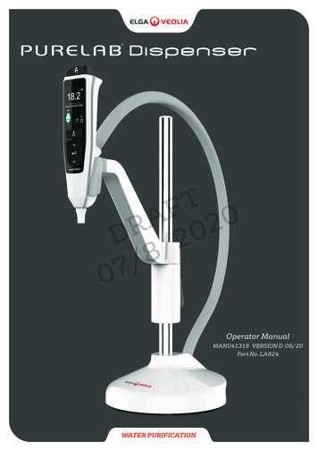
QUICK START GUIDEENGLISHWELCOMEThank you for purchasing a PURELAB Dispenser, please read the Health and Safety notice before proceeding with this installation. HEALTH & SAFETYPlease follow the safety information detailed in the front of theQuick Start Guide. Failure to observe these instructions could result indamage to the equipment and associated equipment resulting injuryor death.LCD DisplayELGA VEOLIATel: 44 (0) 203 567 7300Email: info@elgalabwater.comFlexibleDispenser HoseScreenWebsite: www.elgalabwater.comUnit 10 Lane End Industrial Park, Lane End, High Wycombe, HP14 3BY ELGA VEOLIA is the global laboratory water brand name of Veolia. PURELAB is an ELGA trademark and technology.Dispenser HandsetOwning to a policy of continual improvement, we reserve the right to amendthe specifications given in this document.2020 ELGA VEOLIA / VWS (UK) Ltd. All rights reserved.Handset CradleDispense ButtonWater Purity DisplayHeight AdjustmentScrolling information bar bar indicating the status.ButtonAuto Volume orReservoir VolumeAuto Volume Dispense ButtonUp ButtonAccept ButtonWeighted BaseDown ButtonDispenser TipWorktop MountingBracketCOMMS PortCOMMS PortPURELAB Dispenser Operator Manual MANU41319 Version D 08/20 Page 1Power24V DCPort 5: ReturnPowerPort 1:24V DCInlet
SYSTEM CONFIGURATION - PURELAB QUESTExample 1: 1 X PURELAB Quest RO/DI/UV or RO/DI - 1 X PURELAB Dispenser LA824 (Max 1 Dispenser) - LA648 Boost Pump Quest Port 1: Feedwater InletDispenser Port 1: InletKeyQuest Port 2: OverflowDispenser Port 5: ReturnCOMMSQuest Port 3: DrainQuest Port 6: Dispenser ReturnPowerOptional - LA648 Boost Pump - for feedwater below 2.0 barWaterQuest Port 7: Dispenser Outlet15mm ValveDispenser Type 1Regulator LA512Quest8mm Flow BendMax Distance 5000mm8mm Tube Clip1576Type 12OutletInletAir Break DeviceLA648MAX 1MPotableFeedwaterConnection Existing system configuration: If you are connecting a PURELAB Dispenser to an existing system configuration, please ensure all of your productsare up to date and using the latest software. To find the software version of your existing system, simply turn the power off by the wall and back onagain and the current software version number will be displayed in the bottom right-hand corner of the screen. If your software version number isolder than the one listed on the website at www.elgalabwater.com/customize, then please perform a software update,see section 8.3 'Software Update' in this operator manual. Example 2: 1 X PURELAB Quest RO/DI/UV or RO/DI - 1 X PURELAB Dispenser LA824 - Wall Mounting Bracket LA735Quest Port 1: Feedwater InletDispenser Port 1: InletQuest Port 2: OverflowDispenser Port 5: ReturnQuest Port 3: DrainQuest Port 6: Dispenser ReturnQuest Port 7: Dispenser OutletQuestType 1Dispenser Type 1Max Distance 5000mm762Air Break DeviceWall Mounting Bracket LA735 (INST39088)PotableFeedwaterConnectionPURELAB Dispenser Operator Manual MANU41319 Version D 08/20 Page 25
SYSTEM CONFIGURATION - PURELAB CHORUS 1 ANR/LSC/GSC Example 1: 2 X PURELAB Chorus 3 RO or 2 X PURELAB Chorus 2 RO/DI - 1 X PURELAB Chorus 1 - 3 X PURELAB Dispensers LA824(Max 4 Dispensers) - LA759 60L Reservoir or LA760 100L ReservoirChorus 3 RO or Chorus 2 RO/DI fills an external reservoir with purified Type 3 or Type 2 water, which then feeds a Chorus 1to produce Type 1 water.New system configuration:1. Commission Chorus 3 RO or Chorus 2 RO/DI systems first, directing reservoir port: 4a to drain during this procedure.(Please refer to operator manual Chorus 3 RO MANU39996 or Chorus 2 RO/DI MANU40003 for commissioning instructions)2. Once the reservoir is full, open reservoir port:4a manual valve to Chorus 1 port 1: Feedwater inlet and continue to commission Chorus 1 with the PURELAB Dispensers connected.3. Chorus 1 is set in pre-commisioning mode and will automatically direct water to drain during this procedure.(Please refer to operator manual Chorus 1 MANU39998 for commissioning instructions) Existing system configuration: If you are connecting a PURELAB Dispenser to an existing system configuration, please ensure all of your productsare up to date and using the latest software. To find the software version of your existing system, simply turn the power off by the wall and back onagain and the current software version number will be displayed in the bottom right-hand corner of the screen. If your software version number isolder than the one listed on the website at www.elgalabwater.com/customize, then please perform a software update,see section 8.3 'Software Update' in this operator manual.Chorus Port 1: Feedwater InletChorus Reservoir Port 1: InletDispenser Port 1: InletKeyChorus Port 3: DrainChorus Reservoir Port 4a: OutletDispenser Port 5: ReturnChorus Port 4: Product OutletChorus Reservoir Port 4b: OutletCOMMSChorus Port 5: ReturnChorus Reservoir J1: CommsHalo Dispenser Port 1: InletChorus Port 6: PowerChorus Reservoir J2: CommsPowerHalo Dispenser Port 5: ReturnWaterChorus Port 7: CommsHalo Dispenser Port 6: PowerChorus Port 8: PowerHalo Dispenser Port 7: CommsValveChorus Port 9: CommsHalo Dispenser Port 8: Power15mm ValveHalo Dispenser Port 9: CommsRegulator LA5128mm Flow Bend8mm Tube ClipDispenser Type 1Dispenser Type 1Max Distance 5000mm8mm Equal TDispenser Type 1Max Distance 5000mmChorus 155549573Air BreakDevice6Potable Mains Feedwater ConnectionAir Break DeviceReservoir OverflowAir Break DeviceAir Break Device36Chorus 3 RO or 2 RO/DI478963477Chorus 3 RO or 2 RO/DIJ1Type 3 or 24aJ24bReservoir 60L or 100LPURELAB Dispenser Operator Manual MANU41319 Version D 08/20 Page 3Outlet to Application
SYSTEM CONFIGURATION - PURELAB CHORUS 1 ANR/LSC/GSC Example 2: 1 X PURELAB Chorus 3 RO or 1 X PURELAB Chorus 2 RO/DI - 1 X PURELAB Chorus 1 - 2 X PURELAB Dispensers LA824 LA757 15L Reservoir or LA758 30L Reservoir - Halo Dispenser Wall Mounting Bracket LA768 - Chorus Reservoir Bracket LA770 1 X PURELAB Halo Dispenser LA754 or LA755'See Chorus 1 system configuration notes'Dispenser Type 1Chorus 15Dispenser Type 157Halo 5Halo 75J24a34986Max Distance 5000mmReservoir 15L or 30LType 1Basic or AdvancedType 3 or 2J1Halo 8Halo 9Halo 1ReservoirOverflowHalo DispenserAir Break DevicePotable Mains Feedwater Connection743Air Break Device61Chorus 3 RO or 2 RO/DI Example 3: 1 X PURELAB Chorus 3 RO or 1 X PURELAB Chorus 2 RO/DI - 1 X PURELAB Chorus 1 - 1 X PURELAB Chorus Halo Dispenser LA754 or LA755 - 1 X PURELAB Dispenser LA824 - LA757 15L Reservoir or LA758 30L Reservoir'See Chorus 1 system configuration notes'Reservoir OverflowReservoir 15L or 30L1J14aJ2Halo 8Halo 1Halo 9948716Adding AnAdditional DispenserType 3 or 2Dispenser Type 1Max Distance 5000mmMax Distance 5000mmBasic or AdvancedHalo DispenserType 1Dispenser Type 1Halo 6Halo 71Halo 5535Air Break DeviceChorus 1Potable MainsFeedwater Connection674Air Break Device3Chorus 3 RO or 2 RO/DIChorus 3 RO or 2 RO/DI*PURELAB Dispenser Operator Manual MANU41319 Version D 08/20 Page 415
SYSTEM CONFIGURATION - PURELAB CHORUS 1 ANR/LSC/GSC Example 4: 1 X PURELAB Chorus 3 RO or 1 X PURELAB Chorus 2 RO/DI - 1 X PURELAB Chorus 1 - 2 X PURELAB Dispensers LA824 LA757 15L Reservoir or LA758 30L Reservoir - Chorus Wall Mounting Bracket LA795 - Chorus Reservoir Bracket LA770'See Chorus 1 system configuration notes'Dispenser Type 1Chorus 154986Dispenser Type 1Max Distance 5000mm5Reservoir 15L or 30L4aJ273Type 3 or 2J15ReservoirOverflowAir Break DevicePotable Mains Feedwater Connection743Air Break Device61Chorus 3 RO or 2 RO/DI Example 5: 1 X PURELAB Chorus 3 RO or 1 X PURELAB Chorus 2 RO/DI - 1 X PURELAB Chorus 1 - 1 X PURELAB Chorus Halo Dispenser LA754 or LA755 or LA756 - 1 X PURELAB Dispenser LA824 - LA757 15L Reservoir or LA758 30L Reservoir'See Chorus 1 system configuration notes'Flexible Halo Dispenser Type 1Dispenser Type 1Max Distance 5000mmReservoir Overflow1Type 3 or 24aJ2J1Chorus 1Halo 6Halo 7Halo 5Halo 1Halo 8Halo 9Reservoir 15L or 30L98417653Chorus 11Air Break DevicePotable MainsFeedwater Connection674Air Break Device3Chorus 3 RO or 2 RO/DIChorus 3 RO or 2 RO/DI*PURELAB Dispenser Operator Manual MANU41319 Version D 08/20 Page 55
SYSTEM CONFIGURATION - PURELAB CHORUS 1 COMPLETE AND 2 NON EDI Example 1: 1 X PURELAB Chorus 1 Complete or PURELAB Chorus 2 (Non EDI) - 3 X PURELAB Dispensers LA824 (Max 3 Dispensers) LA759 60L Reservoir or LA760 100L ReservoirChorus 1 Complete and 2 recirculate purified water throught the reservoir for repeated exposure to the purifying technologies.New system configuration:1. Remove and relocate Non-Return-Valve before starting the commissiong procedure.(Please refer to operator manual MANU40932 section 7.2 for details) 2. Commission PURELAB Chorus 1 Complete or PURELAB Chorus 2 system with the dispensers connected, redirecting reservoir port: 4b to drainduring this procedure (Please refer to operator manual MANU40932 section 5.5 for commissioning instructions). Existing system configuration: If you are connecting a PURELAB Dispenser to an existing system configuration, please ensure all of your productsare up to date and using the latest software. To find the software version of your existing system, simply turn the power off by the wall and back onagain and the current software version number will be displayed in the bottom right-hand corner of the screen. If your software version number isolder than the one listed on the website at www.elgalabwater.com/customize, then please perform a software update,see section 8.3 'Software Update' in this operator manual.Chorus Port 1: Feedwater InletDispenser Port 1: InletChorus Port 3: DrainDispenser Port 5: ReturnKeyCOMMSChorus Port 4: Product OutletPowerChorus Port 5: ReturnHalo Dispenser Port 1: InletChorus Port 6: PowerHalo Dispenser Port 5: ReturnWaterChorus Port 7: CommsHalo Dispenser Port 6: PowerValveHalo Dispenser Port 7: CommsChorus Reservoir Port 1: InletHalo Dispenser Port 8: Power15mm ValveChorus Reservoir Port 4a: OutletHalo Dispenser Port 9: CommsRegulator LA512Chorus Reservoir Port 4b: OutletChorus Reservoir J1: Comms8mm Flow BendChorus Reservoir J2: Comms8mm Tube ClipNon-Return-ValveAdding AnAdditional DispenserDispenser Type 1 or Type 2 Chorus 1 Complete or 2 (Non EDI)Max Distance 5000mm7564Dispenser Type 1 or Type 2 Max Distance 5000mm15Max Distance 5000mm153NRV1Potable MainsFeedwater ConnectionAir Break DeviceReservoir Overflow1Air Break Device4aJ1J24bDispenser Type 1 or Type 2 Outlet to ApplicationChorus Reservoir 60L or 100LPURELAB Dispenser Operator Manual MANU41319 Version D 08/20 Page 615
SYSTEM CONFIGURATION - PURELAB CHORUS 1 COMPLETE AND 2 NON EDIExample 2: 1 X PURELAB Chorus 1 Complete or PURELAB Chorus 2 (Non EDI) - 1 X PURELAB Dispenser LA824 LA757 15L Reservoir or LA758 30L Reservoir - 2 X PURELAB Chorus Halo Dispenser LA754 or LA755 or LA756'See Chorus 1 Complete and 2 (Non EDI) system configuration notes'Flexible Halo Dispenser Type 1 or Type 2 Max Distance 5000mmMax Distance 5000mmHalo 7Halo 6Halo 5Halo 9Chorus 1 Complete or 2 (Non EDI)75Basic or Advanced Halo Dispenser Type 1 or Type 2 Halo 1Halo 9Halo 8Halo 146Potable Mains FeedwaterConnection13Reservoir OverflowAir Break Device4aJ1J21NRV4bOutlet to ApplicationChorus Reservoir 15L or 30LPURELAB Dispenser Operator Manual MANU41319 Version D 08/20 Page 7Dispenser Type 1 or Type 2 Max Distance 5000mmHalo 7Halo 6Halo 515
SYSTEM CONFIGURATION - PURELAB CHORUS 2 EDI Example 1: 1 X PURELAB Chorus 2 (EDI) - 3 X PURELAB Dispensers (Max 3 Dispensers) - LA759 60L Reservoir or LA760 100L Reservoir Chorus 2 EDI recirculate purified water throught the reservoir for repeated exposure to the purifying technologies.New System configuration:1. Remove and relocate Non-Return-Valve before starting the commissiong procedure.(Please refer to operator manual MANU40932 section 7.2 for details) 2. Commission PURELAB Chorus 2 EDI with the PURELAB Dispensers connected, water will be automatically redirected to drain through an internalflush valve (V2) during this procedure. (Please refer to operator manual MANU40932 section 5.6 for commissioning instructions)3. Once commissioning is completed the internal EDI filter module will need 'bleeding' before purified water can be dispensed from the Chorus 2 tapor dispensers. (Please refer to operator manual MANU40932 section 5.6 for instructions)Existing system configuration: If you are connecting a PURELAB Dispenser to an existing system configuration, please ensure all of your products are up to date and using the latest software. To find the software version of your existing system, simply turn the power off by the wall and back onagain and the current software version number will be displayed in the bottom right-hand corner of the screen. If your software version number isolder than the one listed on the website at www.elgalabwater.com/customize, then please perform a software update,see section 8.3 'Software Update' in this operator manual.Chorus Port 1: Feedwater InletChorus Reservoir Port 1: InletDispenser Port 1: InletChorus Port 2: EDI DrainChorus Reservoir Port 4a: OutletDispenser Port 5: ReturnChorus Port 3: DrainChorus Reservoir Port 4b: OutletChorus Port 4: Product OutletChorus Reservoir J1: CommsHalo Dispenser Port 1: InletPowerChorus Port 5: ReturnChorus Reservoir J2: CommsHalo Dispenser Port 5: ReturnWaterChorus Port 6: PowerHalo Dispenser Port 6: PowerChorus Port 7: CommsHalo Dispenser Port 7: CommsKeyCOMMSValveHalo Dispenser Port 8: Power15mm ValveHalo Dispenser Port 9: CommsRegulator LA5128mm Flow Bend8mm Tube ClipNon-Return-ValveAdding AnAdditional DispenserDispenser Type 2 Chorus 2 EDIMax Distance 5000mm7564Dispenser Type 2 Max Distance 5000mm15Max Distance 5000mm1532NRV1Potable MainsFeedwater ConnectionAir Break DeviceReservoir Overflow1Air Break Device4aJ1J24bDispenser Type 2 Outlet to ApplicationChorus Reservoir 60L or 100LPURELAB Dispenser Operator Manual MANU41319 Version D 08/20 Page 815
SYSTEM CONFIGURATION - PURELAB CHORUS 2 EDIExample 2: 1 X PURELAB Chorus 2 (EDI) - 1 X PURELAB Dispenser LA824 - LA757 15L Reservoir or LA758 30L Reservoir 2 X PURELAB Chorus Halo Dispenser LA754 or LA755 or LA756'See Chorus 2 (EDI) system configuration notes'Flexible Halo Dispenser Type 2 Max Distance 5000mmBasic or Advanced Halo Dispenser Type 2 Max Distance 5000mmHalo 9Halo 1Halo 7Halo 6Halo 5Halo 9Halo 8Halo 1Chorus 2 EDI7546Potable Mains FeedwaterConnection123Reservoir OverflowAir Break Device4aJ1J21NRV4bOutlet to ApplicationChorus Reservoir 15L or 30LPURELAB Dispenser Operator Manual MANU41319 Version D 08/20 Page 9Dispenser Type 2 Max Distance 5000mmHalo 7Halo 6Halo 515
SET-UP1ENGLISHHOW TO ASSEMBLE AND MAKE HEIGHT ADJUSTMENTSMAX 180 (Fig.1)(Fig.2)a) Insert the handset set into the cradle as shown. (Fig.1)(Fig.3)b) Rotate the handset. (Fig.2)(Fig.4)c) Press and hold the height adjustment button to slidethe handset arm up and down. (Fig.3)d) When you have found the perfect height, release the hight adjustmentbutton to lock into position. (Fig.4)PURELAB Dispenser Operator Manual MANU41319 Version D 08/20 Page 10
SET - UP2 OPTIONAL WORKTOP MOUNTING BRACKETThis is an optional attachment, please skip to section 7 in the Quick Start Guide if you do not need to fit this sercuring bracket.(Fig.5)Caution! Please read the Health and Safety Notices in theCaution! This bracket is only suitable for wooden worktops.front of the Quick Start Guide before proceedingwith this installation.Items not suppliedDrillØ3mm Drill BitPhillips Screw DriverEN388 & EN3743 REMOVING THE SUPPLIED WORKTOP MOUNTING BRACKET(Fig.6)a) Undo the fixing screws screw from the base of the PURELAB Dispenser to remove the mounting bracket.(Fig.6)PURELAB Dispenser Operator Manual MANU41319 Version D 08/20 Page 11Goggles
SET - UP4 MARK AND DRILLING THE HOLES5 REASSEMBLE THE BRACKETØ3mm(Fig.7)(Fig.8)a) Mark and drill two holes into the wooden worktop to a depth ofa) Reassemble the mounting bracket back onto the base30mm using an Ø3mm pilot drill bit. (Fig.7)as shown above. (Fig.8)6 FIXING THE PURELAB DISPENSER TO THE WORKTOPScrew capFixing ScrewScrew cap washer(Fig.9)a) Insert the fixing screws into the screw cap washers. (Fig.9)b) Fix the screws into the pre drilled holes and push the screw caps over the screw heads. (Fig.9)Bracket installations completedPURELAB Dispenser Operator Manual MANU41319 Version D 08/20 Page 12
SET - UP7 CONNECT THE WATER INLETPush in colletRemove Transit PlugFlow BendsTransit Plug(Fig.11)(Fig.10)a) Remove the transit plug from Port 1 water inlet connection.(Fig.10)b) Using the tube supplied, firmly push one end securely intoPort 1 inlet connection. Use the flow bends provided to mouldthe tube into position. (Fig.11)8 CONNECT THE WATER RETURNPush in colletRemove Transit Plug(Fig.12)(Fig.13)a) Remove the transit plug from Port 5 water Return connection.(Fig.12)b) Using the tube supplied, firmly push one end securely into thePort 5 water Return connection. Use the flow bends provided tomould the tube into position. (Fig.13)PURELAB Dispenser Operator Manual MANU41319 Version D 08/20 Page 13
SET - UP9CONNECT THE COMMUNICATIONS CABLES(Fig.14)a) Link the comms cables as shown above,connections may vary depending on yourComms cable from mainsystem configuration. (Fig.14)product or reservoir port10 CONNECT THE POWER CABLES31Comms cable from main(Fig.15)product or reservoir port2Power supplya) Link the power cables as shown above,connections may vary depending on yoursystem configuration. (Fig.15)Caution!(Power supply is supplied with main product)Only use the power supply provided by ELGA VEOLIA.PURELAB Dispenser Operator Manual MANU41319 Version D 08/20 Page 14
SET - UP11 SET LANGUAGE(Fig.16)(Fig.17)a) Press up and down buttons to select your language. (Fig.16)b) Press accept to confirm. (Fig.17)(Language section will only appear on screen if you are setting up a new system configuration.)12 FOLLOW THE ON SCREEN INSTRUCTIONSType 1 or Type 2 handset label.(Fig.20)(Fig.19)b) After completing the commissioningprocedure, please wait for theC) When full purity is reached reached on yourType 1 or Type 2 system configurationreservoir to fill and reach full purityyou can dispense purified water from thebefore dispensing any water. (Fig.19)PURELAB Dispenser. (Fig.20)(Water Purity Alarm will be active(Fig.18)during the commissioning)a) For new system system configurations,follow the on screen commissioninginstructions. (Fig.18)(The Commissioning procedure will only appear on screen if you are setting up a new system configuration.When connecting to an existing system configuration, wait for the purity to be displayed before dispensing)PURELAB Dispenser Operator Manual MANU41319 Version D 08/20 Page 15
1. MANUAL INTRODUCTIONMANUAL INTRODUCTION1.1 Health & SafetyPlease ensure you read the Health & Safety notes in the Quick Start Guide.1.2 Product ModelThis Operator manual has been prepared for PURELAB Dispenser product model: PURELAB Dispenser LA8241.3 Use of this ManualThis manual guides you through the operation and maintenance of PURELAB Dispenserallowing you to obtain a guaranteed supply of purified water to meet your requirements.1.4 InstallationQuick Start Guide shown in the front of this manual shows you how to install PURELAB Dispenser.Quick Reference Guide shows you 'day to day' functions while using the PURELAB Dispenser.1.5 EnvironmentPURELAB Dispenser should be installed on a flat, level surface, in a clean, dry environment it can alsobe mounted to a worktop using the purpose designed bracket, See Quick Start Guide section 2 for details1.6 CommissioningPlease refer to the main product operator manuals for commissioning a new system configuration.Existing system configuration: If you are connecting a PURELAB Dispenser to an existing system configuration, please ensure all ofyour products are up to date and using the latest software. To find the software version of your existing system, simply turn the power offby the wall and back on again and the current software version number will be displayed in the bottom right-hand corner of the screen.If your software version number is older than the one listed on the website at www.elgalabwater.com/customize, then please perform asoftware update, see section 8.3 'Software Update' in this operator manual.1.7 Customer SupportIf you need help with your product, please call your local ELGA Veolia representative.For the address of the nearest ELGA Veolia Sales and Service office visit our website.www.elgalabwater.com or contact ELGA Veolia at: Email: techsupport@elgalabwater.comPURELAB Dispenser Operator Manual MANU41319 Version D 08/20 Page 16
2.GUIDETO YOURPURELABDISPENSERYOURGUIDETO THECHORUSLCD DisplayFlexibleDispenser TubeScreenDispenser HandsetHandset CradleDispense ButtonWater Purity DisplayScrolling information bar bar indicating the status.Height AdjustmentButtonAuto Volume orReservoir VolumeAuto Volume ButtonUp ButtonAccept ButtonWeighted BaseDown ButtonDispenser TipWorktop MountingBracketCOMMS PortCOMMS PortPower24V DCPURELAB Dispenser Operator Manual MANU41319 Version D 08/20 Page 17Port 5: ReturnPowerPort 1:24V DCInlet
3.MAINGUIDEDISPLAYSETTINGSAND BUTTON OPERATIONYOURTO THECHORUSWater Purity DisplayScroll Bar infoReservoir LevelHome ScreenHandset ButtonsMain Menu options tabsScreensaver /Sleep mode*Options tabs will be driven from the main product.Main DisplayWater Purity DisplayMegohm - 1 to 18.2 MΩ(When the water purity falls belowthe default setting, numbers willflash in red indicating that thepurity alarm has been activated)Water Purity DisplayMicro Siemens(This feature can be activated inthe main menu options tabs)Scrolling Information BarAlarms and product information aredisplayed in this scroll bar.Reservoir VolumeReservoir levels and fill status areshown on the display. (Reservoirsymbol flashes red indicating thatthe reservoir is almost empty)Auto Volume DispenseThis feature is activated bypressing the Auto Volume Dispensebutton, volumes are displayed inincremental order and changedwhen the up and down buttons arepressed. Pressing accept buttonstart the dispense.Process symbol,7L100ml*Volumes depend on your system configuration.Shows that the product isperfoming an operation.Button OperationScroll Up ButtonPress to scroll up on a menu or volumeincrements increase in a feature.Scroll Down ButtonPress to scroll down on a menu orvolume increments decrease in afeature.(Press and hold to exit data logging)Dispense ButtonPress for manual dispenseAuto Volume Dispense ButtonPress once to activate and again todeactivate the Auto Volume Dispensefeature.On some products pressing andholding the Auto Volume Dispensebutton will initiate a reservoir refillcycle.Accept ButtonPress the accept button to enter.Press and hold the accept button toenter the main menu options tabs.PURELAB Dispenser Operator Manual MANU41319 Version D 08/20 Page 18
4. PRODUCT CONSUMABLESPart No.DescriptionTypical Service Life*Max. Shelf LifeLC134Point-Of-Use 0.2µm Micro Filter (POU)3 Months2 YearsLC145Point-Of-Use 0.2µm Micro Filter (POU)3 Months2 YearsLC197Point-Of-Use Bio Filter (POU)3 Months2 Years* Consumable life is an estimate only, and will depend on the application.POU FiltersLC134LC145POU FilterLC197(See operator manual maintenance section 7 'Replacing the POU filterLC134 / LC145 / LC197 for details)5. REGISTER YOUR PRODUCT5.1 Registering a ProductTaking the time now to register will mean that we can provide a better service to you in the future.We can contact you about product information and service updates.Why Register your product? Validated your product warranty Proof of product registration Receive software and service updatesHow can I quickly register?The model number and serial number can be found on the ratings plate, see below:MODEL*Serial No.**Maximum PressureInletWorking* Model number** Serial number(bar/psi)(bar/psi)REFER TO OPERATING INSTRUCTIONSSU REFERER AU MANUEL D'OPERATIONIN DER BEDIENUNGSANLEITUNG NACHSEHENELGA Veolia is the global laboratory water brand ofTel: 44 (0) 203 567 7300, Web: www.elgalabwater.comMADE IN THE UKEnter the model and serial number into the online form -productPURELAB Dispenser Operator Manual MANU41319 Version D 08/20 Page 19
6. QUICK REFERENCE GUIDE6.1 Manual Dispense6.2 Continuous DispensePress and hold the dispense button at anytimefor manual dispense, release to stop dispensing.Press the dispense button and acceptbutton together to start continuous dispense.Press dispense button to exit this feature.6.3 Auto Volume Dispense7.0L100mlNote:Water volumesmay vary see thetechnicalspecifications in yourmain product.Press Auto Volume dispensebutton at anytime to open thisfeature.Press up and down buttons,to scroll throught the volumes.PURELAB Dispenser Operator Manual MANU41319 Version D 08/20 Page 20To confirm press dispense buttonto start dispensing the water.
6.QUICKREFERENCEGUIDEYOURGUIDETO THE CHORUS6.4 Deactivating Auto Volume Dispense7.0L100mlPress Auto Volume Dispense button once to deactivate.6.5 ON - OFF, Menu and AcceptNote: Menu options tabsare driven from your mainproduct.02Press and hold accept button for 2 seconds to enterthe Main Menu.Press up and down buttons to scoll throught themain menu options tabs, press accept button toconfirm your selection.PURELAB Dispenser Operator Manual MANU41319 Version D 08/20 Page 21
7.MAINTENANCEYOURGUIDE TO THE CHORUS7.1 Replacing the Point-Of-Use Filter LC134 / LC145 / LC197Step 1 - Removing the Dispense Tip1. Unscrew the dispense tip from underneath the handset (Fig.1).2. Do not dispose of the dispense tip, this part is required for the sanitization procedure(Fig.2).Only use 1 Xo-ringDispense Tip(Fig.1)(Fig.2)Step 2 - Unpacking the LC134 / LC145 / LC197 Point-Of-Use Filter and Installing1. Unpack the new POU filter from it's outer and inner packaging, remove the cap2. Coupler is not required for PURELAB Dispenser, screw in the Point-of-Use filter(Fig.3).(Fig.4).Point-Of-Use LC134 / LC1
WATER PURIFICATION Operator Manual . ELGA VEOLIA Tel: 44 (0) 203 567 7300 Email: info@elgalabwater.com Website: www.elgalabwater.com Unit 10 Lane End Industrial Park, Lane End, High Wycombe, HP14 3BY ELGA VEOLIA is the global laboratory water brand name of Veolia. . to produce Type 1 water. New system configuration: 1. Commission Chorus 3 .