Transcription
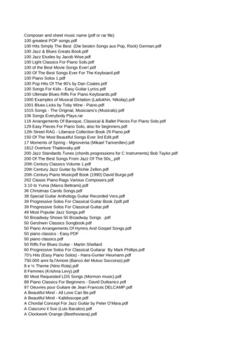
ISSN (Print) : 2320 – 3765ISSN (Online): 2278 – 8875International Journal of Advanced Research in Electrical, Electronics and Instrumentation EngineeringVol. 2, Issue 4, April 2013High Precision Stepper Motor ControllerImplementation on FPGA with GUI on LabVIEWArvind Kumar1, Mrs. M. Valarmathi2M.Tech Scholar [VLSI Design], Dept. of ECE, SRM University, Chennai, India1Assistant Professor, Dept. of ECE, SRM University, Chennai, India2ABSTRACT: Wireless stepper motor controller designed using Very High Speed Integrated Circuit HardwareDescription Language (VHDL) and is implemented on SPARATAN Field Programmable Gate Array (FPGA). Theproposed motor controller is controlled by using Pulse Width Modulation Technique (PWM) thus giving the very highprecision. Due to high torque of stepper motor it is capable of handling the big industrial automation system. In thissystem GUI will be designed using LABVIEW to give the control parameter to the wireless connected stepper motor.Same system can also be used in the mobile robot, functioning in the hazardous area and can be very well equippedwith the nuclear reactor to control the movement of control rod. One of the best use is to track solar energy because theresolution of stepper motor will be highly increased i.e. 0.915 .Keywords: Field Programmable Gate Array (FPGA), Pulse Width Modulation Technique (PWM), High Precision,Wireless Motor Control, Graphical User Interface (GUI), Laboratory Virtual Instrumental Engineering Workbench(LABVIEW).I. INTRODUCTIONHere we have used wireless stepper motor controller designed using Very High Speed Integrated Circuit HardwareDescription Language (VHDL) and is implemented on XILINX SPARATAN Field Programmable Gate Array (FPGA).The proposed motor controller is controlled by using Pulse Width Modulation Technique (PWM) thus giving the veryhigh precision to track solar energy because the resolution of stepper motor will be highly increased i.e. 0.915 . Here noneed of light sensor, because of high precision of motor it will be acting like a sensor giving more efficient and poweroptimized system than the earlier proposed system. The overall power collection efficiency increases from only 45%for a fixed panel to over 60% for the same panel on the tracking system. Due to high torque of stepper motor it iscapable of handling the big solar panel. In this system Graphic User Interface will be used using LABVIEW to give thecontrol parameter to the wireless connected stepper motor. Same system can also be used in the mobile robot,functioning in the hazardous area and can be very well equipped with the nuclear reactor to control the movement ofcontrol rod.II. PREVIOUS WORKA Stepper motor controllers implemented using integrated circuit presented in [12] uses microcontrollers, AT89C51.These models use three phase waveform generator to generate PWM signal. However they are customized for certainapplication only. An open-loop stepper motor driver based on FPGA implementation is presented at [11]. The paperproposes to adjust the duty cycle of the current and voltage inputted into each phase of the motor with an Analogue toDigital Converter (ADC) and sampling regularly for precise positioning purpose. This design involves a numbers ofdiscrete components which are H-bridge circuit, amplifier, anti-aliasing filter and ADC. A Novel stepper motorcontroller based on FPGA hardware implementation is presented at [10]. The paper proposes to use velocity profilegenerator to calculate the index pulses through a time lagging sequence generation algorithm. The latest paper [4] is acost effective wireless reconfigurable controller that uses PWM technique to generate desired signal to control thestepper motor. Here PWM is achieved by manipulating system clock that generates signals necessary to preciselyposition the motor. While in this paper PWM is generated by algorithm written for counter module in the FPGA kit andto precisely control the motor the PWM waveform is varied by increasing the bit count of the counter, thus increasingthe bit count of the counter results in manipulation of duty cycle of the PWM waveform.Pulse-width modulation (PWM) or pulse-duration modulation (PDM) is a modulation technique that conforms thewidth of the pulse, formally the pulse duration. , its main use is to allow the control of the power supplied to electricaldevices, especially to inertial loads such as motors. The term duty cycle describes the proportion of 'on' time to theCopyright to IJAREEIEwww.ijareeie.com1197
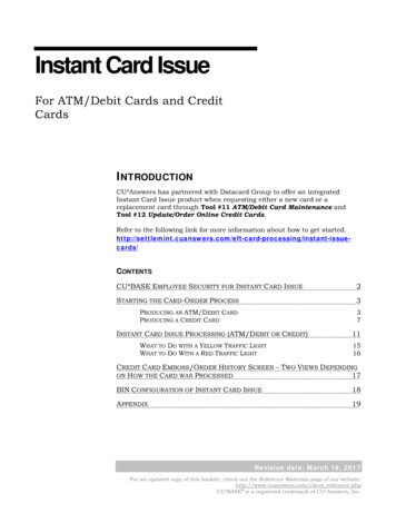
ISSN (Print) : 2320 – 3765ISSN (Online): 2278 – 8875International Journal of Advanced Research in Electrical, Electronics and Instrumentation EngineeringVol. 2, Issue 4, April 2013regular interval or 'period' of time; a low duty cycle corresponds to low power, because the power is off for most of thetime. Duty cycle is expressed in percent, 100% being fully on.Fig. 1 Pulse Width Modulation techniqueIII. STEPPER MOTOR MODELStepper motor is a brushless, open-looped electromechanical device, which can rotate, in a small resolution of angle.It is highly effective in motion control application for high precision and high performance of torque control. Instead, itis low cost, simple and offers better torque performance over wider speed ranges [3]. Stepper motor are used in widerange of precise motion and measurement applications such as nuclear power plant, aeronautics, robotic, automotive,medical, manufacturing industry etc. An ideal example is the pick and place machines used in Surface MountTechnology (SMT) line. Besides, stepper motor is also applied remotely in hazardous and extreme environment such asvolcanic region, atomic or chemical plant, narrow spaces such as in a collapsed building or underground, mountainregion and robotic application such as flying robot. A stepper motor is an electrically powered motor that createsrotation from electrical current driven into the motor. Physically, stepper motors can be large but are often smallenough to be driven by current on the order of milliampere. Fig 2 shows the difference between stepper and DC motor.Current pulses are applied to the motor, and this generates discrete rotation of the motor shaft. This is unlike a DCmotor that exhibits continuous rotation. Although it is possible to drive a stepper motor in a manner where it has nearcontinuous rotation, doing so requires more finesse of the input waveform that drives the stepper motor.𝑁𝑢𝑚𝑏𝑒𝑟 𝑜𝑓 𝑃𝑢𝑙𝑠𝑒𝑠 𝐷𝑒𝑠𝑖𝑟𝑒𝑑 𝐴𝑛𝑔𝑢𝑙𝑎𝑟 ��𝑡𝑒𝑝 𝐴𝑛𝑔𝑙𝑒The number of input electrical pulses is directly proportional to the angular displacement. Where as the pulse widthdetermines the angular speed of the stepper motor. Thus by controlling the pulse width and the number of the pulses itis possible to achieve the desired angle of rotation.Copyright to IJAREEIEwww.ijareeie.com1198
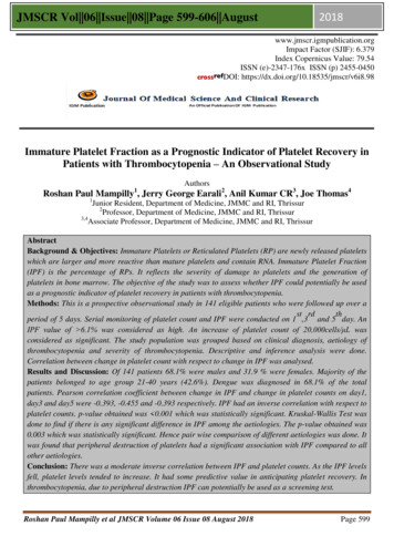
ISSN (Print) : 2320 – 3765ISSN (Online): 2278 – 8875International Journal of Advanced Research in Electrical, Electronics and Instrumentation EngineeringVol. 2, Issue 4, April 2013Fig. 2 Difference between stepper and DC motorIV. PROPOSED ARCHITECTUREProposed architecture shown in the figure 3 consists of Bluetooth adapter module and FPGA development kit. TheGUI is designed using LABVIEW is used to control different-different parameter of the stepper motor [5]. The GUI isdisplayed on the system monitor, the integrated Bluetooth module of the system acts as transmitter that transmit thecontrol signal to the Bluetooth receiver module, now the control signal received at the Bluetooth receiver module istransmitted to the FPGA kit via RS232 cable. Now according to the command signal sent by the operator the ASCIIcode of that particular command will be matched to the VHDL module dumped in the FPGA kit and that specificmodule will be executed to transmit the signal to final control element.Fig. 3 System architectureV. GUI FOR STEPPER MOTOR CONTROLLERIn order to control the stepper motor precisely the graphical user interface is designed in the laptop using NILABVIEW Ver 8.6. So GUI will consist of „3‟ control namely for Angle setup Direction setup (forward and reverse) And last one to setup speed at which motor shaft should rotate.Now, this control signal will be transmitted to FPGA kit, from where the particular VHDL code will be triggered toget the desired output from stepper motor. This control signal will be transmitted to FPGA kit via portable USBBluetooth transmitter will serialize the control signal coming from the laptop and will send it to receiver, where thesignal will be received.The receiver will consist of an encoder circuit that will encode the control signal, this control signal will betransmitted to the FPGA kit via DB9 cable. And from the FPGA kit, driver signal will be boosted using the drivercircuit and then it will be given to stepper motor, so that it should be able to drive stepper motor.Copyright to IJAREEIEwww.ijareeie.com1199
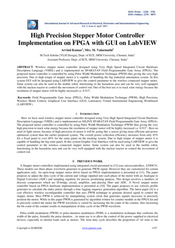
ISSN (Print) : 2320 – 3765ISSN (Online): 2278 – 8875International Journal of Advanced Research in Electrical, Electronics and Instrumentation EngineeringVol. 2, Issue 4, April 2013Fig. 4 Graphical user interfaceVI. VHDL MODEL FOR STEPPER MOTOR CONTROLLERIn stepper motor, the main parameter to be controlled is angular speed, direction and angular displacement. Thisinformation will be transmitted to the stepper motor controller wirelessly at the frequency of 115 KHz using Bluetoothcontroller. The information received at the controller is decoded using the Bluetooth module followed by RS232controller designed in VHDL. And then the data is fed to the signal encoder that converts the data to an understandableformat by the motor driver module. The RTL view of the stepper motor controller is shown in figure 4.For the receiver module, information from the GUI is fed into RS-232 controller via the input Rxd at a designedbaud rate of 115,000 bits per second. The information is then concatenated and shifted in a buffer register for eighttimes and is saved as an 8-bits data.For the transmitter module, when send is triggered, the data is assigned into an eight bits register. Each bit in theregister is sent to Txd output at the designed baud rate is 115,000 bits per second. After all the eight bits is transmitted,the module terminates the transmission until next send is observed.Fig. 4 RTL schematicVII. RESULTThe VHDL design of the controller is implemented on the Spartan 3E FPGA. The result shows that the desiredangular displacement can be obtained by setting the number of pulses count that is internally calculated by thealgorithm, whenever the user inputs the desired angular displacement value that he wants. And if the pulses are given inthe coil in the specific sequence the stepper motor rotates in one direction, otherwise if the direction of sequence isreversed then it rotates in reverse of the previous direction. On testing, the controller is able to communicate wirelesslywith the GUI system for a distance of 10m.Copyright to IJAREEIEwww.ijareeie.com1200
ISSN (Print) : 2320 – 3765ISSN (Online): 2278 – 8875International Journal of Advanced Research in Electrical, Electronics and Instrumentation EngineeringVol. 2, Issue 4, April 2013Fig. 5 Simulation resultTable 1Design summary using Xilinx ISE 13.1Logic UtilizationUsedAvailableUtilizationNumber of Slice Flip Flops6151,92032%Number of 4 input LUTs8591,92044%Number of occupied Slices72196075%Number of Slices containing only related logic721721100%07210%1,3391,92069%Number of Slices containing unrelated logicTotal Number of 4 input LUTsNumber used as logic859Number used as a route-thru480Number of bonded IOBs286642%Number of BUFGMUXs2248%Number of MULT18X18SIOs2450%The table 1 shows the design utilization summary of the proposed system using Xilinx ISE 13.1, after designimplementation, we can verify the device utilization by reviewing the “Design Summary” section. Some variation isexpected between the utilization reported after Synthesis and the utilization reported after Map. For example, with SliceLogic Distribution, Synthesis estimates how the design will be packed and placed into the target architecture, and mapprovides details about the utilization after packing and placement have occurred. In addition, setting physical synthesisMap Properties, such as Global Optimization, Register Duplication, or Logic Optimization, may contribute todifferences in device utilization.VIII. CONCLUSIONThis paper describes a stepper motor controller designed using VHDL and implemented in FPGA. The system iscapable of controlling the stepper motor in terms of step angle at 0.915 . In addition to this we can make it to rotate atCopyright to IJAREEIEwww.ijareeie.com1201
ISSN (Print) : 2320 – 3765ISSN (Online): 2278 – 8875International Journal of Advanced Research in Electrical, Electronics and Instrumentation EngineeringVol. 2, Issue 4, April 2013different – different speeds, displacement clockwise and anticlockwise direction wirelessly. Here GUI is designed forinputting the user defined control parameter to faithfully control the system in industrial automation.One of the major advantages of using LABVIEW is, it acts as a virtual instrument, thus reduces the cost of projectby eliminating the necessity of making control panel. It is user-friendly reduces programming complexity and errorscan be easily identified and rectified.ACKNOWLEDGMENTI sincerely acknowledge in all earnestness, the patronage provided by our Director Dr.C.Muthamizhchelvan,Engineering & Technology, to endeavour this project. I wish to express my deep sense of gratitude and sincere thanksto our Professor and Head of the Department Dr. S. Malarvizhi, for her encouragement, timely help and advice offeredto me. My sincere thanks to our project coordinator Mr. AVM Manikandan, Assistant Professor, Electronics andCommunication Department, for his encouragement and advice. I am very grateful to my guide Mrs. M. Valarmathi,who has guided with inspiring dedication, untiring efforts and tremendous enthusiasm in making this project successfuland presentable.I extend my gratitude and heart full thanks to all the staff and non-teaching staff of Electronics and CommunicationDepartment and to my parents and friends, who extended their kind co-operation by means of valuable suggestions andtimely help during the course of this project [12]E Weise, R Klockner, R Kniel, Ma Sheng Hong, Qin Jian Ping, “Remote Power Supply Using Wind and Solar energy – a Sino-GermanTechnical Cooperation Project”, Beijing International Conference on Wind Energy,Beijing, 1995Damm, J. Issue #17, June/July 1990. An active solar tracking system, HomeBrew Magazine.Stepper Motor, http://en.wikipedia.org/wiki/Stepper motorNandha Kumar Thulasiraman., Haider A.F Mohamed & Yearp Soo Cheng "A Reconfigurable Wireless Stepper Motor Controller Based OnFPGA Implementation”, IEEE symposium on industrial Electronic and Applications, pp.585-590, October 3-5, 2010LabVIEW based advanced Instrumentation System, Springer.LabVIEW VISA Tutorial, www.ni.com/support/visa/vintro.pdfHow Stepper motors work – Images SI, Inc, www.imagesco.com/picstepper/02.htmlMazidi, Mazidi and McKinlay, The 8051 Microcontroller and Embedded Systems : Using Assembly and C.Xilinx ISE 10.1 Quick Start Tutorial, .Daniel Carrica, Marcos A. Funes and Sergio A. Gonzalez, “Novel Stepper Motor Controller Based on FPGA Implementation”, IEEE/ASMETransactions On Mechatronics, Vol 8, No.1, March 2003Ngoc Quy Le and Jai Wook Jeon, “An Open-loop Stepper Motor Driver Based on FPGA”, International Conference on Control, Automationand Systems, Oct. 17-20, 2007H.B. Ling, “The Design of Constant Torque Microstepper Driving Circuit for Stepping Motors Based on AT89C51”, Electronic Engineer,vol.11, no.14, pp.56-61, 2002BIOGRAPHYArvind Kumar received the B.E. degree in Instrumentation and Control Engineering from AtmiyaInstitute of Technology and Science, Gujarat, India, in 2010. He is currently pursuing M.Techdegree in VLSI Design from SRM University, Chennai, India. His current research interests are inVLSI Physical Design.Valarmathi received the B.E. degree in Electronics and Communication Engineering from theRegional Engineering College Trichipalli, Tamil Nadu, India, in 1998 and M.Tech degree from theSastra University, Tanjore, Tamil Nadu, India in 2002. She is currently an Assistant Professorin the Electronics and Communication Engineering department in SRM University, Chennai,India. She has published more than 10 papers in International Conferences and IEEE INDICON2012. Her current research interests include Low PowerVLSI Design, ASIC Design, andCryptography.Copyright to IJAREEIEwww.ijareeie.com1202
proposed motor controller is controlled by using Pulse Width Modulation Technique (PWM) thus giving the very high precision. Due to high torque of stepper motor it is capable of handling the big industrial automation system. In this system GUI will be designed using LABVIEW to give the control parameter to the wireless connected stepper motor.