Transcription
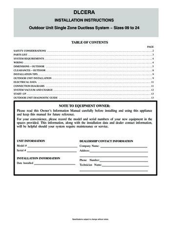
DLCERAINSTALLATION INSTRUCTIONSOutdoor Unit Single Zone Ductless System Sizes 09 to 24TABLE OF CONTENTSPAGESAFETY CONSIDERATIONS . . . . . . . . . . . . . . . . . . . . . . . . . . . . . . . . . . . . . . . . . . . . . . . . . . . . . . . . . . . . . . . . . . . . . . . . . . . . . . . . . 2PARTS LIST . . . . . . . . . . . . . . . . . . . . . . . . . . . . . . . . . . . . . . . . . . . . . . . . . . . . . . . . . . . . . . . . . . . . . . . . . . . . . . . . . . . . . . . . . . . . . . . . 3SYSTEM REQUIREMENTS . . . . . . . . . . . . . . . . . . . . . . . . . . . . . . . . . . . . . . . . . . . . . . . . . . . . . . . . . . . . . . . . . . . . . . . . . . . . . . . . . . . 4WIRING . . . . . . . . . . . . . . . . . . . . . . . . . . . . . . . . . . . . . . . . . . . . . . . . . . . . . . . . . . . . . . . . . . . . . . . . . . . . . . . . . . . . . . . . . . . . . . . . . . . 4DIMENSIONS OUTDOOR . . . . . . . . . . . . . . . . . . . . . . . . . . . . . . . . . . . . . . . . . . . . . . . . . . . . . . . . . . . . . . . . . . . . . . . . . . . . . . . . . . 5CLEARANCES OUTDOOR . . . . . . . . . . . . . . . . . . . . . . . . . . . . . . . . . . . . . . . . . . . . . . . . . . . . . . . . . . . . . . . . . . . . . . . . . . . . . . . . . . 8INSTALLATION TIPS . . . . . . . . . . . . . . . . . . . . . . . . . . . . . . . . . . . . . . . . . . . . . . . . . . . . . . . . . . . . . . . . . . . . . . . . . . . . . . . . . . . . . . . . 9OUTDOOR UNIT INSTALLATION . . . . . . . . . . . . . . . . . . . . . . . . . . . . . . . . . . . . . . . . . . . . . . . . . . . . . . . . . . . . . . . . . . . . . . . . . . . . . 9ELECTRICAL DATA . . . . . . . . . . . . . . . . . . . . . . . . . . . . . . . . . . . . . . . . . . . . . . . . . . . . . . . . . . . . . . . . . . . . . . . . . . . . . . . . . . . . . . . 11CONNECTION DIAGRAMS . . . . . . . . . . . . . . . . . . . . . . . . . . . . . . . . . . . . . . . . . . . . . . . . . . . . . . . . . . . . . . . . . . . . . . . . . . . . . . . . . 11SYSTEM VACUUM AND CHARGE . . . . . . . . . . . . . . . . . . . . . . . . . . . . . . . . . . . . . . . . . . . . . . . . . . . . . . . . . . . . . . . . . . . . . . . . . . . 12START UP . . . . . . . . . . . . . . . . . . . . . . . . . . . . . . . . . . . . . . . . . . . . . . . . . . . . . . . . . . . . . . . . . . . . . . . . . . . . . . . . . . . . . . . . . . . . . . . . 13OUTDOOR UNIT DIAGNOSTIC GUIDE . . . . . . . . . . . . . . . . . . . . . . . . . . . . . . . . . . . . . . . . . . . . . . . . . . . . . . . . . . . . . . . . . . . . . . . 13NOTE TO EQUIPMENT OWNER:Please read this Owner’s Information Manual carefully before installing and using this applianceand keep this manual for future reference.For your convenience, please record the model and serial numbers of your new equipment in thespaces provided. This information, along with the installation data and dealer contact information,will be helpful should your system require maintenance or service.UNIT INFORMATIONDEALERSHIP CONTACT INFORMATIONModel # Company Name:Serial #Address:INSTALLATION INFORMATIONDate InstalledPhone Number:Technician Name:Specifications subject to change without notice.
SAFETY CONSIDERATIONSInstalling, starting up, and servicing air conditioning equipment can behazardous due to system pressures, electrical components, andequipment location (roofs, elevated structures, etc.).Only trained, qualified installers and service mechanics should install,start up, and service this equipment.Untrained personnel can perform basic maintenance functions such ascoil cleaning. All other operations should be performed by trainedservice personnel only.When working on the equipment, observe the precautions in theliterature and on tags, stickers, and labels attached to the equipment.Follow all safety codes. Wear safety glasses and work gloves. Keep aquenching cloth and a fire extinguisher nearby when brazing. Use carein handling, rigging, and setting bulky equipment.Read these instructions thoroughly and follow all warnings or cautionsincluded in literature and attached to the unit. Consult local buildingcodes and National Electrical Code (NEC) for special requirements.Recognize safety information.This is the safety alert symbol !! . When you see this symbol on theunit and in instructions or manuals, be alert to the potential for personalinjury. Understand these signal words: DANGER, WARNING, andCAUTION. These words are used with the safety alert symbol.DANGER identifies the most serious hazards which will result insevere personal injury or death. WARNING signifies hazards whichcould result in personal injury or death. CAUTION is used to identifyunsafe practices which may result in minor personal injury or productand property damage.WARNING!ELECTRICAL SHOCK HAZARDFailure to follow this warning could result in personalinjury or death.Before installing, modifying, or servicing system, mainelectrical disconnect switch must be in the OFFposition. There may be more than 1 disconnect switch.Lock out and tag switch with a suitable warning label.!WARNINGEXPLOSION HAZARDFailure to follow this warning couldresult in death, serious personal injury,and/or property damage.Never use air or gases containingoxygen for leak testing or operatingrefrigerant compressors. Pressurizedmixtures of air or gases containingoxygen can lead to an explosion.!CAUTIONEQUIPMENT DAMAGE HAZARDFailure to follow this caution may result in equipmentdamage or improper operation.Do not bury more than 36 in. (914 mm) of refrigerant pipein the ground. If any section of pipe is buried, there must bea 6 in. (152 mm) vertical rise to the valve connections onthe outdoor units. If more than the recommended length isburied, refrigerant may migrate to the cooler buried sectionduring extended periods of system shutdown. This causesrefrigerant slugging and could possibly damage thecompressor at start up.2Specifications subject to change without notice.32801001101
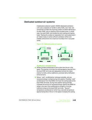
PARTS LISTTable 1—Parts ListPART NO.PART NAMEQTY.1Outdoor unit1-Literature package including installation instructions and warranty1-Grommet to secure the outdoor unit (helps with vibration prevention during unit operation)4-Drain Joint1-Drain Hose1 Outdoor1A150766Fig. 1 - Parts ListNOTE:SIf the outdoor unit is higher than the indoor unit, prevent rain from flowing into the indoor unit along the connection pipe by making adownward arc in the connection pipe before it enters the wall to the indoor unit. This ensures that rain drips from the connection pipe beforeit enters the wall.SSPiping and the interconnecting wiring are field supplied.The illustration above is only a sketch. Different models may be slightly different.Table 2 lists the units are covered in this manual.Table 2—Unit SizesCooling OnlyHeating Pump32801001101SYSTEM TONSBTUhVOLTAGE - ,000208/230-1DLCERAH24AAKSpecifications subject to change without notice.OUTDOOR MODEL3
SYSTEM REQUIREMENTSAllow sufficient space for airflow and service of the unit. See Fig. 5 for the required minimum distances between the unit, walls or ceilings.PipingIMPORTANT: Both refrigerant lines must be insulated separately.S Table 3 contains piping information for the product covered within this document.Table 3—Piping and Refrigerant InformationSystem SizePiping12K (115V)9K (208-230V)12K (208-230V)18 (208-230V)Min. Piping Lengthft. (m)10 (3)10 (3)10 (3)10 (3)10 (3)Standard Piping Lengthft. (m)24.6 (7.5)24.6 (7.5)24.6 (7.5)24.6 (7.5)24.6 (7.5)Max. outdoor-indoorheight difference(OU higher than IU)ft. (m)33 (10)33 (10)33 (10)66 (20)66 (20)Max. outdoor-indoorheight difference(IU higher than OU)ft. (m)33 (10)33 (10)33 (10)66 (20)66 (20)Max. Piping Length withno additional refrigerantcharge per System(Standard Piping length)ft. (m)24.6 (7.5)24.6 (7.5)24.6 (7.5)24.6 (7.5)24.6 (7.5)Total Max. PipingLength per systemft. (m)82 (25)82 (25)82 (25)98 (30)164 (50)Additional refrigerantcharge (between Standard Oz/ft (g/m)– Max piping length)0.161 (15)0.161 (15)0.161 (15)0.161 (15)0.322 (30)Suction Pipe(size - connection type)In (mm)ø1/2 (12.7)ø3/8 (9.52)ø1/2 (12.7)ø1/2 (12.7)ø5/8 (15.9)Liquid Pipe(size - connection type)In (mm)ø1/4 (6.35)ø1/4 (6.35)ø1/4 ( 6.35)ø1/4 ( 6.35)ø3/8 (9.52)TypeR410AR410AR410AR410AR410ALbs (kg)1.30 (0.59)1.06 (0.48)1.30 (0.59)2.1 (0.95)2.65 (1.2)Lbs (kg)2.12 (0.96)1.76 (0.8)2.12 (0.96)2.82 (1.28)3.97 (1.8)Refrigerant TypeCooling Only ModelsRefrigerant Charge AmountHeat Pump ModelsCharge Amount24K (208-230V)All outdoor units have an electronic expansion valve to manage the refrigerant flow of the fan coil connected.WIRINGAll wires must be sized per NEC (National Electrical Code) or CEC(Canadian Electrical Code) and local codes. Use Electrical Data tableMCA (minimum circuit amps) and MOCP (maximum over currentprotection) to correctly size the wires and the disconnect fuse orbreakers respectively.Recommended Connection Method for Power and CommunicationWiring:The main power is supplied to the outdoor unit. The field supplied 14/3stranded wire with ground with a 600 volt insulation rating,power/communication wiring from the outdoor unit to indoor unitconsists of four (4) wires and provides the power for the indoor unit.Two wires are line voltage AC power, one is communication wiring (S)and the other is a ground wire. Wiring between indoor and outdoor unitis polarity sensitive. The use of BX wire is NOT recommended.If installed in a high Electromagnetic field (EMF) area andcommunication issues exists, a 14/2 stranded shielded wire can be usedto replace L2/N and (S) between outdoor unit and indoor unit landingthe shield onto ground in the outdoor unit only.4!CAUTIONEQUIPMENT DAMAGE HAZARDFailure to follow this caution may result in equipmentdamage or improper operation.Wires should be sized based on NEC and local codes.!CAUTIONEQUIPMENT DAMAGE HAZARDFailure to follow this caution may result in equipment damageor improper operation.Be sure to comply with local codes while running wire fromthe indoor unit to the outdoor unit.Every wire must be connected firmly. Loose wiring may causethe terminal to overheat or result in unit malfunction. A firehazard may also exist. Ensure all wiring is tightly connected.No wire should touch the refrigerant tubing, compressor orany moving parts.Disconnecting means must be provided and shall be locatedwithin sight and readily accessible from the air conditioner.Connecting cable with conduit shall be routed through thehole in the conduit panel.Specifications subject to change without notice.32801001101
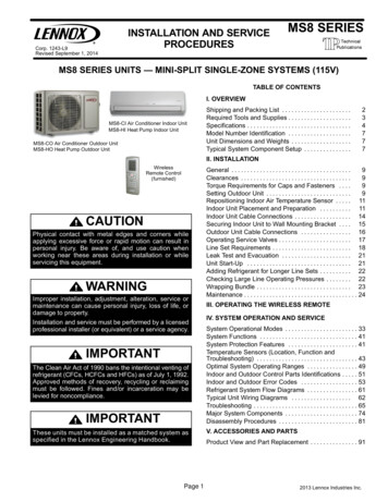
DIMENSIONS OUTDOORTable 4—Dimensions and WeightsSystem Size12K(115V)CoolingOnlyWidth (W) in. (mm)30.31(770)Depth (D) in. (mm)11.81(300)Weight-Net lbs. 45)14.29(363)88.6(40.2)Height (H) in. (mm)21.85(555)Width (W) in. (mm)30.31(770)Depth (D) in. (mm)11.81(300)Weight-Net lbs. (kg)69.0(31.3)63.0(28.6)System Size12K(115V)HeatPumpHeight (H) in. 29(363)114.2(51.8)0.47(12) 21.85(555)30.66(779) W3H19.17(487) W111.81(300) D11.26(286)2.36(60)13.07(322)D2 D32.76(70) W0.98(25) B111.73(298)3.54(90) B230.31(770) WD12.42(61.5) A2H1Unit: inch(mm).2R03.66(93)4(6)H20.47(12) A1Fig. 2 - Sizes 9K and 12K32801001101Specifications subject to change without notice.5
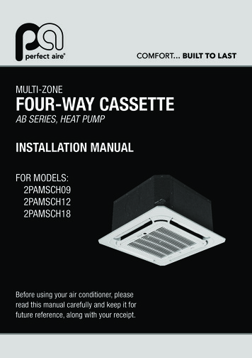
H0.47 (1 2)21.81 (554)DIMENSIONS OUTDOOR (CONT)20.24 (514)13.11 (333)DW131.50 (800)2.76 (7 0)W22.43 (6 1.8)B1D3D1H1R03.37 (8 5.5)B213.39 (340)D212.24 (311)12.80 (325)2.36 (6 0)4.17 (1 06)W. 79(R20)0.87 (2 2)A1R 0.24 (R 6)H22.43 (6 1.6)A2Unit: inch(mm)Fig. 3 - Size 18K6Specifications subject to change without notice.32801001101
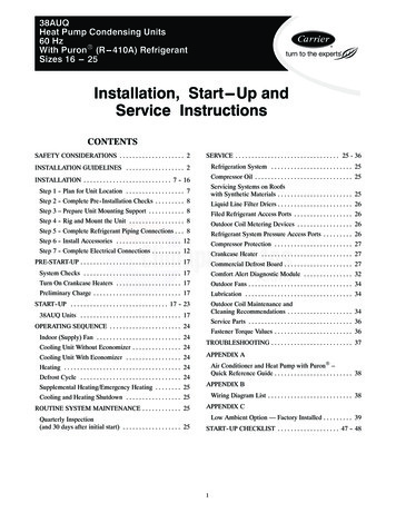
DIMENSIONS OUTDOOR (CONT)Unit: inch (mm)Fig. 4 - Size 24K32801001101Specifications subject to change without notice.7
CLEARANCES OUTDOORFig. 5 - Outdoor Unit ClearanceTable 5—Outdoor Unit Clearance DimensionsUNITAMINIMUM VALUE in. (mm)24 (610)B24 (610)C24 (610)D4 (101)E4 (101)NOTE: The outdoor unit must be mounted at least 2in. (50mm) above the maximum anticipated snow depth.Fig. 6 - Clearance for Multiple Units8Specifications subject to change without notice.32801001101
INSTALLATION TIPSIdeal installation locations include:Outdoor UnitS A location which is convenient to installation and not exposed tostrong winds.S A location which can bear the weight of the outdoor unit and wherethe outdoor unit can be mounted in a level position.S A location which provides appropriate clearances (see Fig. 5).S Do not install the indoor or outdoor units in a location with specialenvironmental conditions. For those applications, contact yourDuctless representative.OUTDOOR UNIT INSTALLATION1. Locate the outdoor unit and connect piping and wiring.!CAUTIONEQUIPMENT DAMAGE HAZARDFailure to follow this caution may result in equipment damageor improper operation.In regions with snowfall and cold temperatures, avoidinstalling the outdoor unit in areas where it can be covered bysnow. If the outdoor unit is installed in areas where heavysnow is expected, a field supplied ice or snow stand and/orfield supplied installed wind baffle should be installed toprotect the unit from snow accumulation and/or blocked airintake. Blocking the air intake may result in reduced airflow,significantly reduced performance and damage to theequipment.NOTE: Install the outdoor unit on a rigid base to reduce noise levelsand vibration. Determine the optimal air outlet direction to preventdischarged air from being blocked. If the installation site is exposed tostrong winds such as a coastal areas, ensure the fan’s proper operationby installing the unit lengthwise along the wall or use dust or shieldplates. If the unit needs to be suspended, the installation bracket shouldcomply with the suspension requirements in the installation bracketdiagram. The installation wall should be solid brick, concrete or thesame intensity construction, or take steps to reinforce and dampen thesupport. The connection between the bracket and the wall as well as thebracket and the air conditioner should be firm, stable and reliable.Ensure there is no obstacle which may block the radiating air.A07350Fig. 7 - High Wind InstallationMAKE REFRIGERANT PIPING CONNECTIONS(OUTDOOR UNIT)IMPORTANT: Use refrigeration grade tubing ONLY. No other typeof tubing may be used. Use of other types of tubing will void themanufacturer’s warranty.Inserting the tubing into the insulation before making the connections willsave time and improve installation quality.1. Remove the service valve cover, if provided with the unit.2. Cut the pipe, with a pipe cutter, at 90 degrees (see Fig. 8).3. Remove the service connection, if provided with the unit.A150767Fig. 8 - Cut the Pipe4. Remove all the burrs from the cut cross section of the pipeavoiding any burrs inside the tubes.5. Remove the flare nuts attached to the indoor and outdoor units.6. Install the correct size flare nut onto the tubing and make a flareconnection. Refer to Table 6 for the flare nut spaces.Table 6—Flare Nut SpacingOUTER DIAM. )A150768Fig. 9 - Flare Nut Spacing7. Apply a small amount of refrigerant oil to the flare connectionon the tubing.8. Align the center of the pipes and/or service valve.A150769Fig. 10 - Align Pipe Center9. Connect both the liquid and gas piping to the indoor unit.10. Tighten the flare nut using a torque wrench as specified inTable 7.11. Complete the installation.Table 7—Tightening TorquePIPE DIAMETER In.(mm)Ø1/4” (6.35)Ø3/8” (9.52)Ø1/2” (12.7)Ø5/8” (15.88)Do not open the service valves or remove the protective caps from thetubing ends until all connections are made.Bend the tubing with bending tools to avoid kinks and flat spots.Keep the tubing free of dirt, sand, moisture, and other contaminants toavoid damaging the refrigerant system.Avoid sags in the suction line to prevent the formation of oil traps. Insulateeach tube with a minimum 3/8 in. (10 mm) wall thermal pipe insulation.32801001101A (mm)Max.0.05 (1.3)0.06 (1.6)0.07 (1.8)0.09 (2.2)Specifications subject to change without notice.TIGHTENING TORQUEFt-lbN-m10 to 1313.6 to 17.624 to 3132.5 to 42.037 to 4650.1 to 62.350 to 6067.7 to 81.3A150770Fig. 11 - Tighten the Flare Nut9
!CAUTIONCAUTION!EQUIPMENT DAMAGE HAZARDEQUIPMENT DAMAGE HAZARDFailure to follow this caution may result in equipmentdamage or improper operation.Failure to follow this caution may result in equipmentdamage or improper operation.S Be sure to comply with local codes while running wirefrom indoor unit to outdoor unit.S Every wire must be connected firmly. Loose wiring maycause the terminal to overheat or result in unitmalfunction. A fire hazard may also exist. Therefore,ensure all wiring is tightly connected.S No wire should be allowed to touch the refrigeranttubing, compressor or any moving parts.S Disconnecting means must be provided and shall belocated within sight and readily accessible from the airconditioner.S Connecting cable with the conduit shall be routedthrough hole in the conduit panel.Excessive torque can break the flare nut depending oninstallation conditions.INSTALL ALL POWER AND INTERCONNECTINGWIRING TO OUTDOOR UNITS1. Mount the outdoor power disconnect.2. Run the power wiring from the main box to disconnect perNEC and local codes.3. Remove the field wiring cover from the unit by loosening thescrews.4. Remove the caps on the conduit panel.5. Connect the conduit to conduit panel (see Fig. 12).6. Properly connect both the power supply and control lines to theterminal block per the connection diagram for the appropriateunit capacity and voltage.7. Ground the unit in accordance with NEC and local electricalcodes.8. Use the lock nuts to secure the conduit.9. Reinstall the field wiring cover.Outdoor unitTerminal BlockOver 1.57" (40mm)Conduit panelConduitA07455Fig. 12 - Field Wiring10Specifications subject to change without notice.32801001101
DRAIN CONNECTIONSInstall drains must meet local sanitation codes.Install the outdoor unit drain jointFit the seal into the drain joint, then insert the drain joint into the basepan hole of the outdoor unit. Rotate 90 to securely assemble them.Connect the drain joint with an extension drain hose to avoidcondensate from draining off the outdoor unit during heating mode.NOTE: Basepan built in with multiple holes for proper drainingduring defrost. For applications where it is required to seal these holes,and re direct the condensate drain, rubber plugs are available throughRCD.Table 8—Rubber PlugsOutdoor UnitModel NumberBasepan BaseRubber PlugsRCD Part NumberQuantity per unitDLCERAA12AAJDLCERAA12AAKSealDrain jointBase pan holeDLCERAA24AAKDLCERAH12AAJDLCERAH09AAKSealBase injointDLCERAH18AAK13DLCERAH24AAK25Fig. 13 - Drain JointImages are for illustration purposes only.!CAUTIONIn cold climates, ensure the drain hose is as vertical aspossible to ensure swift water drainage.If water drains too slowly, it can freeze in the hose and floodthe unit.32801001101Specifications subject to change without notice.11
ELECTRICAL DATATable 9—Electrical Data (Cooling Only)Outdoor Unit )(208/230-1-60)(208/230-1-60)Max – Min*Oper. Voltage127-104253-187253-187MCA137111625Cooling OnlyPower SupplyMOCP201515RLA9.54.5711FLA0.60.40.50.6Rated oor Fan Motor253-187Table 10—Electrical Data (Heat Pump)Outdoor Unit Size12KVolts-PH-Hz(115-1-60)Max – Min*Oper. Voltage127-104Heat PumpPower 0.50.6Rated sorOutdoor Fan Motor9K(208/230-1-60) (208/230-1-60) (208/230-1-60) (208/230-1-60)*Permissible limits of the voltage range at which the unit will operate satisfactorily.LEGENDFLA - Full Load AmpsMCA - Minimum Circuit AmpsMOCP - Maximum Over-Current ProtectionRLA - Rated Load AmpsCONNECTION DIAGRAMSFig. 14 - Connection DiagramsNotes:1. Do not use the thermostat wire for any connection between indoor and outdoor units.2. All connections between indoor and outdoor units must be as shown. The connections are sensitive to polarity and will result in a fault code.12Specifications subject to change without notice.32801001101
SYSTEM VACUUM AND CHARGE!CAUTIONLEAK INSYSTEMMICRONSUNIT DAMAGE re to follow this caution may result in equipmentdamage or improper operation.Never use the system compressor as a vacuum pump.Refrigerant tubes and the indoor coil should be evacuated using therecommended 500 microns deep vacuum method. The alternate tripleevacuation method may be used if the procedure outlined below isfollowed.NOTE: Always break a vacuum with dry nitrogen.VACUUM TIGHTTOO WETTIGHTDRY SYSTEM0USING VACUUM PUMP123 45MINUTES67A954241. Completely tighten flare nuts A, B, C, D, connect the manifoldgage charge hose to a charge port of the low side service valve(see Fig. 15).2. Connect the charge hose to vacuum pump.3. Fully open the low side of manifold gage (see Fig. 16).4. Start the vacuum pump.5. Evacuate using either the deep vacuum or triple evacuationmethod.6. After evacuation is complete, fully close the low side ofmanifold gage and stop the vacuum pump operation.7. The factory charge contained in the outdoor unit is good for upto 25 ft. (8 m) of line length. For refrigerant lines longer than25 ft. (8 m), add refrigerant, up to the allowable length, asspecified in the System Requirements section.8. Disconnect the charge hose from the charge connection of thelow side service valve.9. Fully open service valves B and A.10. Securely tighten the service valve caps.Fig. 17 - Deep Vacuum GraphTRIPLE EVACUATION METHODThe triple evacuation method should only be used when the vacuumpump is only capable of pumping down to 28 in. of mercury vacuumand the system does not contain any liquid water.Refer to Fig. 18 and proceed as follows:1. Pump the system down to 28 in. of mercury and allow thepump to continue operating for an additional 15 minutes.2. Close the service valves and shut off the vacuum pump.3. Connect a nitrogen cylinder and regulator to the system andopen until the system pressure is 2 psig.4. Close the service valve and allow the system to stand for 1 hr.During this time, dry nitrogen can diffuse throughout thesystem absorbing moisture.5. Repeat this procedure as indicated in Fig. 18. The system willthen be free of any contaminants and water vapor.EVACUATEBREAK VACUUM WITH DRY NITROGENWAITEVACUATEA07360BREAK VACUUM WITH DRY NITROGENFig. 15 - Service ValveWAITEVACUATECHECK FOR TIGHT, DRY SYSTEM(IF IT HOLDS DEEP VACUUM)RELEASE CHARGE INTO SYSTEMA95425A07361Fig. 18 - Triple Evacuation MethodFig. 16 - ManifoldDEEP VACUUM METHODFINAL TUBING CHECKThe deep vacuum method requires a vacuum pump capable of pulling avacuum of 500 microns and a vacuum gage capable of accuratelymeasuring this vacuum depth. The deep vacuum method is the best way toassure a system is free of air and liquid water (see Fig. 17).IMPORTANT: Check to be certain factory tubing on both the indoorand outdoor unit has not shifted during shipment. Ensure tubes are notrubbing against each other or any sheet metal. Pay close attention to thefeeder tubes, making sure wire ties on feeder tubes are secure and tight.32801001101Specifications subject to change without notice.13
START UPOUTDOOR UNITTest OperationPerform a test operation after completing a gas leak and electrical safetycheck. See the indoor unit installation instructions and owner’s manualfor additional start up information.Are there unusual noises or vibrations during operation?Explain the Following Items to the Customer (with the aid of theOwner’s Manual):1. Explain care and maintenance.2. Present the installation instructions to the customer.SYSTEM CHECKS1. Conceal the tubing where possible.2. Make sure the drain tube slopes downward along its entirelength.3. Ensure all tubing and connections are properly insulated.4. Fasten the tubes to the outside wall, when possible.5. Seal the hole through which the cables and tubing pass.OUTDOOR UNIT DIAGNOSTIC GUIDESFor ease of service, the systems are equipped with a diagnostic code display LEDs on both the indoor and outdoor units. The outdoor diagnostic isdisplayed on the outdoor unit microprocessor board.There may be a few error codes displayed in the indoor unit that might relate to the outdoor unit’s problems. If possible, always check the diagnosticcodes displayed on the indoor unit first.The diagnostic codes displayed on the outdoor units are listed on Table 11.Table 11—Unit Diagnostic GuidesDISPLAYE1F0LED STATUSCommunication malfunction between indoor and outdoor units.Protection of over-currentF1F2F3F4F5Open circuit or short circuit of outdoor ambient temperature sensor T4Open circuit or short circuit of condenser coil temperature sensor T3Open circuit or short circuit of Compressor discharge temperature sensor T5Outdoor unit EEPROM errorOutdoor fan speed has been out of controlP0P1P2P3P4IPM malfunctionOver voltage or over low voltage protectionHigh temperature protection of compressor topOutdoor low temperature protectionInverter compressor drive errorP7J0J1J2J3Outdoor IGBT temperature sensor errorHigh temperature protection of indoor coil in heatingOutdoor temperature protection of outdoor coil in coolingDischarge temperature protectionProtection of active PFC moduleJ4J5J6J8Communication error between control board and IPM boardHigh-pressure switch protectionLow-pressure switch protectionAC voltage protectionFor additional diagnostic information, refer to the Service Manual.Copyright 2018 CMNA 1025 Cobb Place Blvd NWKennesaw, GA 3015214Specifications subject to change without notice.32801001101
INSTALLATION INSTRUCTIONS Outdoor Unit Single Zone Ductless System . within sight and readily accessible from the air conditioner. Connecting cable with conduit shall be routed through the hole in the conduit panel. 32801001101 Specifications subject to change without notice. 5