Transcription
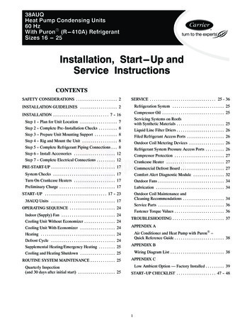
38AUQHeat Pump Condensing Units60 HzWith PuronR (R---410A) RefrigerantSizes 16 --- 25Installation, Start---Up andService InstructionsCONTENTSSAFETY CONSIDERATIONS . . . . . . . . . . . . . . . . . . . . 2SERVICE . . . . . . . . . . . . . . . . . . . . . . . . . . . . . . . . 25 - 36INSTALLATION GUIDELINES . . . . . . . . . . . . . . . . . . 2Refrigeration System . . . . . . . . . . . . . . . . . . . . . . . . . 25INSTALLATION . . . . . . . . . . . . . . . . . . . . . . . . . . . 7 - 16Compressor Oil . . . . . . . . . . . . . . . . . . . . . . . . . . . . . . 25Servicing Systems on Roofswith Synthetic Materials . . . . . . . . . . . . . . . . . . . . . . . 25Step 1 - Plan for Unit Location . . . . . . . . . . . . . . . . . . 7Step 2 - Complete Pre-- Installation Checks . . . . . . . . . 8Liquid Line Filter Driers . . . . . . . . . . . . . . . . . . . . . . . 26Step 3 – Prepare Unit Mounting Support . . . . . . . . . . . 8Filed Refrigerant Access Ports . . . . . . . . . . . . . . . . . . 26Step 4 - Rig and Mount the Unit . . . . . . . . . . . . . . . . . 8Outdoor Coil Metering Devices . . . . . . . . . . . . . . . . . 26Step 5 - Complete Refrigerant Piping Connections . . . 8Refrigerant System Pressure Access Ports . . . . . . . . . 26Step 6 - Install Accessories . . . . . . . . . . . . . . . . . . . . 12Compressor Protection . . . . . . . . . . . . . . . . . . . . . . . . 27Step 7 - Complete Electrical Connections . . . . . . . . . 12Crankcase Heater . . . . . . . . . . . . . . . . . . . . . . . . . . . . 27PRE-START-UP . . . . . . . . . . . . . . . . . . . . . . . . . . . . . . . 17Commercial Defrost Board . . . . . . . . . . . . . . . . . . . . . 27System Checks . . . . . . . . . . . . . . . . . . . . . . . . . . . . . . 17Comfort Alert Diagnostic Module . . . . . . . . . . . . . . . 32Turn On Crankcase Heaters . . . . . . . . . . . . . . . . . . . . 17Outdoor Fans . . . . . . . . . . . . . . . . . . . . . . . . . . . . . . . . 34Preliminary Charge . . . . . . . . . . . . . . . . . . . . . . . . . . . 17Lubrication . . . . . . . . . . . . . . . . . . . . . . . . . . . . . . . . . 34START-- UP . . . . . . . . . . . . . . . . . . . . . . . . . . . . . . 17 - 23Outdoor Coil Maintenance andCleaning Recommendations . . . . . . . . . . . . . . . . . . . . 3438AUQ Units . . . . . . . . . . . . . . . . . . . . . . . . . . . . . . . 17Service Parts . . . . . . . . . . . . . . . . . . . . . . . . . . . . . . . . 36OPERATING SEQUENCE . . . . . . . . . . . . . . . . . . . . . . 24Indoor (Supply) Fan . . . . . . . . . . . . . . . . . . . . . . . . . . 24Cooling Unit Without Economizer . . . . . . . . . . . . . . . 24Cooling Unit With Economizer . . . . . . . . . . . . . . . . . 24Fastener Torque Values . . . . . . . . . . . . . . . . . . . . . . . . 36TROUBLESHOOTING . . . . . . . . . . . . . . . . . . . . . . . . . 37APPENDIX AAir Conditioner and Heat Pump with PuronR –Quick Reference Guide . . . . . . . . . . . . . . . . . . . . . . . . 38Heating . . . . . . . . . . . . . . . . . . . . . . . . . . . . . . . . . . . . 24Defrost Cycle . . . . . . . . . . . . . . . . . . . . . . . . . . . . . . . 24Supplemental Heating/Emergency Heating . . . . . . . . 25APPENDIX BWiring Diagram List . . . . . . . . . . . . . . . . . . . . . . . . . . 38Cooling and Heating Shutdown . . . . . . . . . . . . . . . . . 25ROUTINE SYSTEM MAINTENANCE . . . . . . . . . . . . 25Quarterly Inspection(and 30 days after initial start) . . . . . . . . . . . . . . . . . . 25APPENDIX CLow Ambient Option — Factory Installed . . . . . . . . . 39START-- UP CHECKLIST . . . . . . . . . . . . . . . . . . . 47 - 481
SAFETY CONSIDERATIONS!38AUQImproper installation, adjustment, alteration, service,maintenance, or use can cause explosion, fire, electricalshock or other conditions which may cause personalinjury or property damage. Consult a qualified installer,service agency, or your distributor or branch forinformation or assistance. The qualified installer oragency must use factory-authorized kits or accessorieswhen modifying this product. Refer to the individualinstructions packagePERSONAL INJURY AND ENVIRONMENTALHAZARDFailure to follow this warning could cause personalinjury or death.Relieve pressure and recover all refrigerant beforesystem repair or final unit disposal.Wear safety glasses and gloves when handlingrefrigerants. Keep torches and other ignitions sourcesaway from refrigerants and oils.Follow all safety codes. Wear safety glasses and workgloves. Use quenching cloths for brazing operations andhave a fire extinguisher available. Read these instructionsthoroughly and follow all warnings or cautions attached tothe unit. Consult local building codes and appropriatenational electrical codes (in USA, ANSI/NFPA70,National Electrical Code (NEC); in Canada, CSA C22.1)for special requirements.!!WARNINGELECTRICAL SHOCK HAZARDFailure to follow this warning could cause in personalinjury or death.Before performing service or maintenance operationson unit, always turn off main power switch to unit andinstall lockout tag. Unit may have more than onepower switch.!WARNINGUNIT OPERATION AND SAFETY HAZARDFailure to follow this warning could cause personalinjury, death and/or equipment damage.PuronR (R-- 410A) refrigerant systems operate athigher pressures than standard R-- 22 systems. Do notuse R-- 22 service equipment or components on Puronrefrigerant equipment.CAUTIONCUT HAZARDFailure to follow this caution may result in personalinjury.Sheet metal parts may have sharp edges or burrs. Usecare and wear appropriate protective clothing, safetyglasses and gloves when handling parts and servicing38AUQ units.It is important to recognize safety information. This is the. When you see this symbol on thesafety-- alert symbolunit and in instructions or manuals, be alert to thepotential for personal injury.Understand the signal words DANGER, WARNING,CAUTION, and NOTE. These words are used with thesafety-alert symbol. DANGER identifies the most serioushazards which will result in severe personal injury ordeath. WARNING signifies hazards which could result inpersonal injury or death. CAUTION is used to identifyunsafe practices, which may result in minor personalinjury or product and property damage. NOTE is used tohighlight suggestions which will result in enhancedinstallation, reliability, or operation.WARNINGINSTALLATION GUIDELINEReplacement /Retrofit – R22 to Puron Split system heat pumps are intended to be installed withmatching indoor sections only. The 38AUQ heat pumpoutdoor units are matched only with same-size 40RUQindoor sections. Existing R-22 indoor coils cannot beconverted to R-410A heat pump duty. Only the existingrefrigerant piping is a candidate for retrofit use.Acid test – If the existing system is being replacedbecause of a compressor electrical failure, assume acid isin system. If system is being replaced for any otherreason, use an approved acid test kit to determine acidlevel. If even low levels of acid are detected, install a 100percent activated alumina suction line filter drier inaddition to the replacement liquid-line filter drier. Operatethis system in COOLING ONLY. Remove the suction linefilter drier as soon as possible, with a maximum of 72 hrof operation.Recommendation: Install a ball valve in the liquid line atthe filter drier location when installing a suction filter inthe suction line.Installation –1. Remove the existing evaporator coil or fan coil andinstall the replacement coil.2. Drain oil from low points and traps in suction linetubing if they were not replaced.3. Remove the existing outdoor unit. Install the new outdoor unit according to these installation instructions.4. Install the factory-supplied liquid-line filter drier atthe indoor coil just upstream of the TXV.2
!7. Operate the system for 10 hr. Monitor the pressuredrop across the suction line filter drier. If pressuredrop exceeds 3 psig (21kPa), replace suction-line andliquid-line filter driers. Be sure to purge system withdry nitrogen and evacuate when replacing filterdriers. Continue to monitor the pressure drop acrosssuction-line filter drier. Repeat filter changes is necessary. Never leave suction-line filter drier in systemlonger than 72 hr (actual time).CAUTIONUNIT DAMAGE HAZARDFailure to follow this caution may result in equipmentdamage or improper operation.Never install suction-- line filter drier in the liquid-- lineof a PuronR system.38AUQ5. If required, install a 100% activated alumina suctionline filter drier at the outdoor unit.6. Evacuate and charge the system according to the instructions in this installation manual.Fig. 1 - 38AUQ*16 Unit Dimensions3C10674
38AUQFig. 2 - 38AUQ*25 Unit Dimensions4C10675
Table 1A — Physical Data — 38AUQ*16-25 Units — 60 Hz EnglishUNIT SIZE 38AUQ*1625NOMINAL CAPACITY (tons)1520REFRIGERANTSYSTEM‡RefrigerantPuronR (R--- 410A)# Circuits / # Compressor / Type2 / 2 / Scroll2 / 2 / -Pressure Trip / Reset (psig)630 / 505630 / 505Low---Pressure Trip / Reset (psig)27 / 4427 / 44ZP83 (2)ZP103 (2)6011035003500Shipping Charge A/B (lb)Operating Charge w/FanCoil†A/B (lbs)Metering DeviceModelOil Charge A/B (oz)Speed (RPM)OUTDOOR COILMaterialAl/CuCoil TypeRound Tube/Plate Fin (RTPF)Rows/Fins Per Inch (FPI)Total Face Area2/17(ft2)47.150.1Qty / Motor Drive Type3 / Direct4 / DirectMotor HP / RPM¼ / 1100¼ / 1100222210,00014,000970115044 544 5Qty.Vapor2.13/82.13/8Qty.Liquid2.1/22.1/2OUTDOOR FAN / MOTORDiameter (in)Nominal Airflow (Cfm)Watts (Total)Cut-inPIPING CONNECTIONS (in. ODS)LEGENDODS — Outside Diameter Sweat (socket)† Approximate system charge with 25 ft piping of sizes indicated with matched 40RUQ538AUQCOMPRESSOR
Table 1B — Physical Data — 38AUQ*16-25 Units — 60 Hz SIUNIT SIZE 38AUQ*1625NOMINAL CAPACITY (kW)1520REFRIGERANTSYSTEM‡RefrigerantPuronR (R--- 410A)# Circuits / # Compressor / Type2 / 2 / Scroll2 / 2 / High---Pressure Trip / Reset (kPa)4344 / 34824344 / 3482Low---Pressure Trip / Reset (kPa)372 / 807372 / 807ZP83 (2)ZP103 (2)Oil Charge A/B (L)1.73.2Speed (r/s)5858Shipping Charge A/B (kg)Operating Charge w/FanCoil†A/B (kg)Metering Device38AUQCOMPRESSORModelOUTDOOR COILMaterialAl/CuCoil TypeRound Tube/Plate Fin (RTPF)Rows/Fins Per Meter (Fins/m)Total Face Area2/17(m2)4.44.63 / Direct4 / DirectMotor HP / r/s¼ / 18¼ / 18Diameter (mm)559559Nominal Airflow (L/s)47196607Watts (Total)970115044 544 5Qty / Vapor2 / 34.92 / 34.9Qty / Liquid2 / 12.72 / 12.7OUTDOOR FAN / MOTORQty / Motor Drive TypeCut-inPIPING CONNECTIONS (mm ODS)LEGENDNEMA — National Electrical Manufacturers AssociationODS — Outside Diameter Sweat (socket)† Approximate system charge with 7.6 m piping of sizes indicated with matched 40RUQ6
1238 A U Q A 2345678910 11 12 13 14 15 16 17 185 A 0 C 6– 0 A 0 A 0Model TypePackaging38AU Carrier Condensing UnitPuronr R--- 410A Refrigerant1 LTL0 StandardType of CoilQ Heat Pump Scroll CompressorElectrical OptionsA NoneC Non-Fused DisconnectRefrigerant OptionsA NoneB Low AmbientService Options0 None1 Un-powered Convenience Outlet2 Powered Convenience OutletNominal Tonnage16 15 Tons25 20 TonsNot UsedA Not Used38AUQNot UsedA Place HolderBase Unit Controls0 Electro-Mechanical ControlsNot Used0 Not UsedDesign RevisionA Initial Rev (Discrete Model Number)Coil OptionsA Al/CuB Precoat Al/CuC E-Coat Al/CuE Cu/CuM Al/Cu with Hail GuardN Precoat Al/Cu with Hail GuardP E-Coat Al/Cu with Hail GuardR Cu/Cu with Hail GuardVoltage1 575/3/605 208/230/3/606 460/3/60C10676Fig. 3 - Model Number NomenclaturePOSITION NUMBERTYPICAL142831POSITION1 23 456 10405G617283INSTALLATIONJobsite SurveyComplete the following checks before installation.1. Consult local building codes and the NEC (NationalElectrical Code) ANSI/NFPA 70 for special installation requirements.2. Determine unit location (from project plans) or selectunit location.3. Check for possible overhead obstructions which mayinterfere with unit lifting or rigging.105DESIGNATESWeek of manufacture (fiscal calend ar)Year of manufacture (”10” 2010)Manufacturing location (G ETP, Texas, USA)Seq uential numb erFig. 4 - Serial Number Nomenclature.94C10799Step 1 — Plan for Unit LocationSelect a location for the unit and its support system (pad,rails or other) that provides for the minimum clearancesrequired for safety. This includes the clearance tocombustible surfaces, unit performance and service accessbelow, around and above unit as specified in unitdrawings. See Fig. 5.Select a unit mounting system that provides adequateheight to allow for removal and disposal of frost and icethat will form during the heating-defrost mode.NOTE: Consider also the effect of adjacent units onairflow performance and control box safety clearance.7
Do not install the outdoor unit in an area where fresh airsupply to the outdoor coil may be restricted or whenrecirculation from the condenser fan discharge is possible.Do not locate the unit in a well or next to high walls.Evaluate the path and required line length forinterconnecting refrigeration piping, including suctionriser requirements (outdoor unit above indoor unit), liquidline lift (outdoor unit below indoor unit) and hot gasbypass line. Relocate sections to minimize the length ofinterconnecting tubing.38AUQAlthough unit is weatherproof, avoid locations that permitwater from higher level runoff and overhangs to fall ontothe unit.LEFT:Min 18” (457 mm)requried for serviceNOTE: If vibration isolators are required for a particularinstallation, use the data in Figs. 1 and 2 to make theproper selection.Step 3 — Prepare Unit Mounting SupportSlab Mount —DO NOT BURY REFRIGERATION LINES.REAR:Min 18” (457 mm)requried for serviceS The unit may be mounted on a level pad directly on thebase channels or mounted on raised pads at supportpoints. See Tables 1A and 1B for unit operatingweights. See Figs. 1 and 2 for weight distribution basedon recommended support points.RIGHT:Min 18” (457 mm)requried for serviceFRONT:42” (1067 mm)Note: Observe requirements for 39” (914 mm) operating clearanceon either Left or Rear coil opening.C10201Fig. 5 - Service Clearance Dimensional DrawingStep 2 — Complete Pre-Installation ChecksCheck Unit Electric Characteristic —Confirm before installation of unit that voltage, amperageand circuit protection requirements listed on unit data plateagree with power supply provided.Un-- crate Unit —Remove unit packaging except for the top skid assembly,which should be left in place until after the unit is riggedinto its final location.Inspect Shipment —File a claim with shipping company if the shipment isdamaged or incomplete.Provide a level concrete slab that extends a minimum of 6in. (150 mm) beyond unit cabinet. Install a gravel apron infront of condenser coil air inlet to prevent grass andfoliage from obstructing airflow.Step 4 — Rig and Mount the UnitRigging —These units are designed for overhead rigging. Refer tothe rigging label for preferred rigging method. Spreaderbars are not required if top crating is left on the unit. Allpanels must be in place when rigging. As furtherprotection for coil faces, plywood sheets may be placedagainst the sides of the unit, behind cables. Run cables toa central suspension point so that the angle from thehorizontal is not less than 45 degrees. Raise and set theunit down carefully.If it is necessary to roll the unit into position, mount theunit on longitudinal rails, using a minimum of 3 rollers.Apply force to the rails, not the unit. If the unit is to beskidded into position, place it on a large pad and drag itby the pad. Do not apply any force to the unit.Raise from above to lift the unit from the rails or padwhen unit is in its final position.After the unit is in position, remove all shipping materialsand top crating.Step 5 — Complete Refrigerant PipingConnectionsRefrigerant lines must be carefully designed andconstructed to ensure equipment reliability and efficiency.Line length, pressure drop, compressor oil return, andvertical separation are several of the design criteria thatmust be evaluated. See Table 2.Consider System Requirements —IMPORTANT: Do not bury refrigerant pipingunderground.S Consult local building codes and National ElectricalCode (NEC, U.S.A.) for special installationrequirements.IMPORTANT: A refrigerant receiver is notprovided with the unit. Do not install a receiver.S Allow sufficient space for airflow clearance, wiring,refrigerant piping, and servicing unit. See Figs. 1 and 2for unit dimensions and weight distribution data.S Locate the unit so that the outdoor coil (condenser)airflow is unrestricted on all sides and above.8
Table 2 – 38AUQ*16-- 25 Piping Recommendations (Two-Circuit Unit)R-410AModelNominal Capacity38AUQ*16Equivalent LengthLength Equiv0-3838-7575-113113-150150-188Length Lin0-2525-5050-7575-100100-125Liquid Line1/1/1/1/1/22222Max r Line38AUQ*2588Charge ea. (lbs)20.922.8Liquid Line1/1/224.85/281/85/28811/826.628.65/5/88Max Lift253750245148Heat255050606060Vapor Line11/11/Charge ea. 840.2Legend:Length EquivEquivalent tubing length, including effects of refrigeration specialties devicesLinear LinTypical linear tubing length, Feet (50% added to linear to define Equivalent Length for this table)Liquid LineTubing size, inches OD.Max LiftMaximum liquid lift (indoor unit ABOVE outdoor unit only), at maximum permitted liquid line pressure drop —S Linear Length Less than 100 ft: Minimum 2.0 F subcooling entering TXVS Linear Length Greater than 100 ft: Minimum 0.5 F subcooling entering TXVVapor LineTube size, inches ODChargeCharge Quantity, lbs. Calculated for both liquid line sizes (where applicable), but only with larger suction line size(where applicable)NOTE:For applications with equivalent length greater than 188 ft (57 m) and/0r linear length greater than 125 ft (38 m),contact your local Carrier representative.Check Vertical Separation —If there is any vertical separation between the indoor andoutdoor units, check to ensure that the separation is withinallowable limits. Relocate equipment if necessary.Provide Safety Relief —If local codes dictate an additional safety relief device,purchase locally and install locally. Installation willrequire the recovery of the factory shipping charge beforethe factory tubing can be cut and the supplemental reliefdevice is installed.Refrigerant Line Sizing —Consider the length of the piping required between theoutdoor and indoor units. The maximum allowable linelength is 100 ft (30.5 m). See Table 2. Refrigerant vaporpiping should be insulated.Install Filter Driers and Moisture Indicators —38AUQ units include two Puron-duty filter driers, shippedin cartons attached to the unit basepan. Remove the filterdriers and prepare to install in the liquid lines at theevaporator coil. Do not remove connection fitting plugsuntil ready to connect and braze the filter driers into theliquid line positions See Table 3.IMPORTANT: A refrigerant receiver is notprovided with the unit. Do not install a receiver.Installation of liquid line moisture indicating sightglass ineach circuit is recommended. Locate the sightglass(es)between the outlet of the filter drier and the TXV inlet.Refer to Table 4 for recommendations on refrigerationspecialties.Select the filter drier for maximum unit capacity andminimum pressure drop. Complete the refrigerant pipingfrom the indoor unit to the outdoor unit before openingthe liquid and suction lines at the outdoor unit.Every unit MUST have bi-directional filter driers in theliquid lines. Locate the filter driers at the indoor unit,close to the evaporator coil’s thermal expansion valve(TXV) inlets.938AUQCool
Table 3 – Puron-duty Filter Drier(s)LiquidLine mePartNumber Ref2-in16 cu. in.KH43LG0892-in16 cu. in.KH43LG089Table 4 – Refrigerant Specialties Part NumbersLIQUID LINESIZE (in.)LIQUID LINESOLENOID VALVE (LLSV)SOLENOIDCOILSIGHTGLASSFILTERDRIER1/2EF680035 plus EF680039 biflow kitEF680037KM6800045/8EF680036 plus EF680039 biflow kitEF680037KM680005Provided with unitSee Table 438AUQInstall Liquid Line Solenoid Valves —It is recommended that bi-directional solenoid valves beplaced in the main liquids line for circuits 1 and 2 (seeFig. 6) between the outdoor unit and the indoor coil.Locate the solenoid valves at the end of the liquid lines,near the outdoor unit connections, with flow directionarrow pointed at the outdoor unit. Refer to Table 4. (Aliquid line solenoid valve is required when the liquid linelength exceeds 75 ft [23 m].) This valve preventsrefrigerant migration (which causes oil dilution) to thecompressor during the off cycle, at low outdoor ambienttemperatures. Wire the solenoid according to the unit labeldiagram.!EQUALIZER LINETXVSENSINGBULBAIRFLOW15 DIAMSMIN10DIAMSTXVCKT 28 DIAMSMINTXVSENSINGBULBAIRFLOW15 KT 18 DIAMSMINUNIT DAMAGE HAZARDFailure to follow this caution may result in equipmentdamage.Failure to use a solenoid valve relay (SUR) accessorymay cause overload of Comfort Alert DiagnosticModule (CADM) and compressor alarm lock out.SUCTIONCIRCUIT 2SUCTIONCIRCUIT 1Dual Circuit Coil Piping ConfigurationC10830Fig. 6 - Location of Sight Glasses and Filter DriersTable 5 – Minimum Outdoor Air Operating TemperatureCapacity Control Liquid Line Solenoid Valve —Evaporator capacity control via liquid solenoid valve isnot recommended for use with 38AUQ 100MINIMUM OUTDOORTEMP — F (C)*Standard UnitHead PressureControl†35 (1.7)–20 (–28.9)35 (1.7)–20 (–28.9)Applies to Cooling mode of operation only.Wind baffles (field-supplied and field-installed) are recommended for allunits with low ambient head pressure control. Refer to Low AmbientControl Installation Instructions (shipped with accessory) for details.
Make Piping Connections —Evacuation/Dehydration —Piping connections at the 38AUQ unit are ball valves withstub tube extensions. Do not open the unit service valvesuntil all interconnecting tube brazing as been completed.Evacuate and dehydrate the connected refrigerationsystem(s) (excluding the 38AUQ unit) to 500 micronsusing a two-stage vacuum pump attached to the serviceports outside the 38AUQ service valves, followingdescription in GTAC II, Module 4, System Dehydration.!WARNINGUNIT OPERATION AND SAFETY HAZARDFailure to follow this warning could cause personalinjury, death and/or equipment damage.PuronR (R-- 410A) refrigerant systems operate athigher pressures than standard R-- 22 systems. Do notuse R-- 22 service equipment or components on Puronrefrigerant equipment.Field ServiceAccess Port(Schrader core)FactoryHigh-FlowAccess PortIMPORTANT: Charge in Cooling mode only!Preliminary Charge —Service Valvewith Stem CapSweatConnectionFig. 7 - Typical Piping Connection AssemblyC10203When connecting the field tubing to the 38AUQ servicevalves, wrap the valves in wet rags to prevent overheatingPressure-test all joints from outdoor unit connections overto the indoor coil, using nitrogen as pressure and withsoap-and-bubbles.Before starting the unit, charge R-410A liquid refrigerantinto the high side of each 38AUQ circuit through theliquid service valve(s). The amount of refrigerant addedmust be at least 80% of the operating charge listed inTable 2 for LINEAR line length LESS the factory chargequantity (if factory shipping charge has not beenremoved). See the following example.When pressure-testing is completed, remove the nitrogensource at the outdoor unit service valves and re-install thetwo Schrader valve cores. Torque the cores to 2-3 in-lbs(23-34 N-cm).Allow high and low side pressures to equalize. If pressuresdo not equalize readily, charge R-410A vapor (usingspecial service manifold with expansion device) into thesuction line service port for the low side of system toassure charge in the evaporator. Refer to GTAC II,Module 5, Charging, Recover, Recycling, andReclamation for liquid charging procedures.Where vapor line is exposed to outdoor air, line must beinsulated. See Table 6 for insulation requirements.Example:38AUQ*25Table 6 – Insulation for Vapor Line Exposedto Outdoor ConditionsLENGTH OF EXPOSEDVAPOR LINE*ftm102550*†INSULATION THICKNESS†in.mm33/81081/213153/419Recommended vapor line insulation for piping exposed to outdoorconditions to prevent loss of heating during heating cycle. When vaporline goes through interior spaces, insulation should be selected to prevent condensation on cooling cycle. Heating capacity should be reduced 1000 Btuh (295 W) if over 35 ft (11 m) of vapor line with 3/4 in. (19mm) insulation is exposed to outdoor conditions.Closed cell foam insulation with a thermal conductivity of: 0.28 Btu Sin./ft2 S h S F (0.04 W/m S C).60-ft (18.3 m) linear line lengthEquivalent line length 90-ft (27.4 m)Cooling Liquid Lift: 20-ft (6.1 m)Select line sizes from Table 2 (38AUQ):Liquid 1/2 - in (provides liquid lift to 24-- ft (7.3 m))Vapor 1-1/8 in.Charge (each circuit):1/ - in liquid line: 30.7 lbs (at 75-ft linear length)280% of Operating Charge:0.80 x 30.7 24.6 lbsFactory Shipping Charge: 9 lbsField-Charge (each circuit):24.6 - 9.0 15.6 lbsFor linear line lengths longer than 125 ft (38.1 m), contactyour local Carrier representative for system charge value.1138AUQThe stub tube connections include π-in SAE servicefittings with Schrader valve cores (see Fig. 7). Beforemaking any brazed connections to the unit service valves,remove both Schrader valve caps and cores and save forre-installation. Connect a source for nitrogen to one ofthese service fittings during tube brazing to prevent theformation of copper oxides inside the tubes at brazedjoints.
Step 6 — Install AccessoriesAccessories requiring modifications to unit wiring shouldbe completed now. These accessories may include WinterStart controls, Low Ambient controls, phase monitor,Compressor LOCout. Refer to the instructions shippedwith the accessory.NOTE: TEST LEADS - Unit may be equipped with shortleads (pigtails) on the field line connection points oncontactor C or optional disconnect switch. These leads arefor factory run-test purposes only; remove and discardbefore connecting field power wires to unit connectionpoints. Make field power connections directly to lineconnection pressure lugs only.Step 7 — Complete Electrical Connections38AUQ!!WARNINGELECTRICAL SHOCK HAZARDFailure to follow this warning could result in personalinjury or death.Do not use gas piping as an electrical ground. Unitcabinet must have an uninterrupted, unbroken electricalground to minimize the possibility of personal injury ifan electrical fault should occur. This ground may consistof electrical wire connected to unit ground lug in controlcompartment, or conduit approved for electrical groundwhen installed in accordance with NEC (NationalElectrical Code); ANSI/NFPA 70, latest edition (inCanada, Canadian Electrical Code CSA [CanadianStandards Association] C22.1), and local electricalcodes.FIRE HAZARDFailure to follow this warning could result inintermittent operation or performance satisfaction.Do not connect aluminum wire between disconnectswitch and condensing unit. Use only copper wire.(See Fig. 8.)ELECTRICDISCONNECTSWITCHCOPPERWIRE ONLYNOTE: Check all factory and field electrical connectionsfor tightness. Field-supplied wiring shall conform with thelimitations of 63 F (33 C) rise.ALUMINUMWIREField Power Supply —If equipped with optional Powered Convenience Outlet:The power source leads to the convenience outlet’stransformer primary are not factory connected. Installermust connect these leads according to required operationof the convenience outlet. If an always-energizedconvenience outlet operation is desired, connect thesource leads to the line side of the unit-mounteddisconnect. (Check with local codes to ensure this methodis acceptable in your area.) If a de-energize via unitdisconnect switch operation of the convenience outlet isdesired, connect the source leads to the load side of theunit disconnect. On a unit without a unit-mounteddisconnect, connect the source leads to compressorcontactor C and indoor fan contactor IFC pressure lugswith unit field power leads.All units except 208/230-v units are factory wired for thevoltage shown on the nameplate. If the 208/230-v unit isto be connected to a 208-v power supply, the controltransformer must be rewired by moving the black wirewith the 1/4-in. female spade connector from the 230-vconnection and moving it to the 208-v 1/4-in. maleterminal on the primary side of the transformer. Refer tounit label diagram for additional information.Field power wires are connected to the unit at line-sidepressure lugs on compressor contactor C and TB1 (seewiring diagram label for control box componentarrangement) or at factory-installed option non-fuseddisconnect switch. Max wire size is #4 AWG (copper only).WARNINGFig. 8 - Disconnect Switch and UnitA93033Units Without Factory-Installed Disconnect —When installing units, provide a disconnect switch perNEC (National Electrical Code) of adequate size.Disconnect sizing data is provided on the unit informativeplate. Locate on unit cabinet or within sight of the unit pernational or local codes. Do not cover unit informativeplate if mounting the disconnect on the unit cabinet.Units with Factory-Installed Disconnect —The factory-installed option disconnect switch is locatedin a weatherproof enclosure located under the maincontrol box. The manual switch handle is accessiblethrough an opening in the access panel.All Units All field wiring must comply with NEC and all local codes.Size wire based on MCA (Minimum Circuit Amps) on theunit informative plate. See Fig. 9 for power wiringconnections to the unit power terminal block and equipmentground. Maximum wire size is #4 ga AWG per pole.Provide a
door unit according to these installation instructions. 4. Install the factory-supplied liquid-line filter drier at . Model ZP83 (2) ZP103 (2) Oil Charge A/B (L) 1.7 3.2 Speed (r/s) 58 58 OUTDOOR COIL Material Al/Cu . Check for possible overhead obstructions which may interfere with unit lifting or rigging. Step 1 — Plan for Unit Location