Transcription
XitaniumLED outdoor driversJune, 2016June, 2016Design-in guide - Philips Xitanium Outdoor LED drivers1
Published versionsJune, 20162Design-in guide - Philips Xitanium Outdoor LED driversJune, 2016
ContentsContents3Introduction to this guideApplicationsInformation or supportDetermine which documents contain what information5555Safety precautionsSafety warnings and instructions66Introduction to Xitanium Outdoor LED DriversIntroductionXitanium LED driver versionsFeaturesNaming of the LED outdoor drivers777710Electrical Design-inOperating windowHow to Select an appropriate driverDriver wiring and pinningAdjustable Output Current (AOC) – set the driver output currentHow to Determine AOC priority with LED driversHow to Set the output current via RsetHow to Set the output current via LEDsetHow to Program the output currentMains voltage fluctuationsInrush currentHow to Determine the number of drivers on a MCBSurge protectionLeakage currentElectromagnetic compatibility (EMC)How to Improve EMI performanceElectrical isolation and protective earth1111121213131415202021222323242526June, 2016Design-in guide - Philips Xitanium Outdoor LED drivers3
Thermal Design-InIntroductionDefinitionsCase Temperature Point (Tc point)How to Measure Tc at the Tc pointRelationhip between Tc and ambient temperatureDriver lifetimeModule Temperature Protection (MTP)2929292929303030Mechanical Design-In32IP rating32Installation33Controllability35Control characteristics35Non-dimmable351-10 V Dimming36DALI37PWM37Integrated programmable dimming protocols38How to Connect to and program driver42How to See the programming taking effect42ConfigurabilityIntroductionPhilips MultiOne Interface toolPhilips MultiOne SoftwareSystem requirementsGetting StartedMultiOne SystemSettings4343434444444545Quality and ReliabilitySwitching & cycling lifetime of LED driversElectrical failures due to switching Vmains on and offMechanical failures due to thermal cyclingStandards the drivers are tested against46464646494Design-in guide - Philips Xitanium Outdoor LED driversJune, 2016
Introduction to this guideThank you for choosing Philips Xitanium Outdoor LED drivers. Inthis guide you will find the information needed to integrate thesedrivers into a LED luminaire or LED system.This edition describes the Xitanium Outdoor LED driversoptimized for outdoor application. We advise you to consult ourwebsites for the latest up-to-date information.ApplicationsThe Xitanium Outdoor LED drivers are designed to operate LEDsolutions for outdoor lighting, like industrial, street, road lightingand open area environments. If you use Philips LED drivers incombination with Philips LED modules, specific design-in guidesare available from below mentioned technology websites.IP67 Independent versionClassificationThe Xitanium outdoor driver listed as below can be used in bothClass I and Class II IEC isolation systems.Built-in versionInformation or supportPlease consult your local Philips office or visit:www.philips.com/technologyDetermine which documents contain whatinformationIn order to provide information in the best possible way, Philips’philosophy on product documentation is the following. Commercial leaflet contains product family information &system combinations Datasheet contains the product specific specifications Design-in guide describes how the product is to bedesigned-inBuilt-in versionDatasheetAll these documents can be found on the download page of theOEM website www.philips.com/technology. If you require anyfurther information or support please consult your local Philipsoffice.Commercial leafletJune, 2016Design-in guideDesign-in guide - Philips Xitanium Outdoor LED drivers5
Safety precautionsWarnings: Avoid touching live parts! Do not use drivers with damaged housing and/orconnectors! Do not use drivers with damaged wiring! Class I luminaires must be connected to protective earth! Do not service the driver when the mains voltage isconnected; this includes connecting or disconnectingthe LED load. Switchable function to make the open load on the driveroutput is abnormal condition, it is not an intendedapplication that be allowed. For the driver claimed class II isolation, the EQUI mustconnected with luminaire grounding reference.Safety warnings and instructions Do not use damaged or defective contacts or housings. Do not use damaged products. Cap off all unused wires to prevent accidental contact with theluminaire or driver housing. For the drivers with IP-rated connectors, the installers shallcheck that the seal of the connector is present and notdamaged before connecting the male/female connectors. For connector version drivers, when luminaire manufacturerschoose to cut off the connector, the original IP-rating cannotbe guaranteed and becomes the responsibility of the luminairemanufacturers. The luminaire manufacturer is responsible for its own luminairedesign and has to comply with all relevant safety standards. Philips offers the LED outdoor drivers with two differenthousing designs, built-in and independent. The built-in typedrivers should not be exposed to the elements such as snow,water and ice. Exposure will lead to corrosion and evenfailure of the driver what should be avoided. It is the luminairemanufacturer’s responsibility to prevent exposure.The independent type drivers can be exposed to the outdoorelements and installed apart from fixture.Philips Design-in support is available; please contact yourPhilips sales representative.6Design-in guide - Philips Xitanium Outdoor LED driversJune, 2016
Introduction to Xitanium OutdoorLED DriversIntroductionXitanium Outdoor LED drivers are designed to operate LEDsolutions for outdoor lighting applications such as flood, street,road lighting as well as open area environments.The operating points are chosen specifically to match the mostcommonly used LEDs.IP67 Independent versionXitanium LED driver versionsThe Xitanium LED drivers described in this guide are availablein different versions, e.g. fixed-output and dimmable (1-10V;PWM; Line Switch; DALI ), in a wide range of power ratings thatenable the most popular light output levels for general lightingapplications. We recommend you always check our Xitanium LEDdriver leaflet for the most up-to-date overview of our range. Thisleaflet can be found on thewww.philips.com/technology website.FeaturesBuilt-in versionJune, 2016Adjustable Output Current (AOC)Flexibility in luminaire design is ensured by the adjustable outputcurrent (AOC).The adjustable output current enables operation of variousLED configurations from different LED manufacturers whilstalso ensuring the solution remains “future proof ” for new LEDgenerations. The output current can be set with an externalresistor (Rset). With our Programmable drivers, the outputcurrent setting can also be programmed using the PhilipsMultiOne programming hardware interface and the matchingsoftware “MultiOne driver configurator”.More information about AOC and how to set the output currentcan be found in de chapter “Electrical design”Design-in guide - Philips Xitanium Outdoor LED drivers7
ControllabilityThe Xitanium Outdoor LED drivers are available in 3 differentversions: Fixed Output 1-10V dimming DALI PWM Line Switch Amp DimThe way of controlling is shown in the name of the driver. If nodimming protocol is given in the name, the Xitanium driver canonly be used as a fixed output driver. The output current can beset as described in the Electrical design chapter. More informationabout the dimming protocols can be found in the Controllabilitychapter.Thermal de-ratingThermal de-rating of your LED PCB is possible by integrating anNTC (Negative Thermal Coefficient) component on the LEDPCB and connect this NTC to the driver's NTC input. Moredetails about the NTC resistor can be found in the Chapter“Temperature design”Module Temperature Protection (MTP, adjustable onprogrammable drivers only)This feature helps to protect the LEDs when operated in a hotambient environment. The driver helps to regulate LED moduletemperature by regulating the output current. An NTC (NegativeTemperature Coefficient resistor) must be present on the LEDmodule and connected to respective pins on the driver in orderto be able to make use this feature. Programmable drivers allowfor changing the dimming behavior.More information can be found under chapter ThermalManagement.8Design-in guide - Philips Xitanium Outdoor LED driversJune, 2016
Constant Light Output (CLO, programmable drivers only)Traditional light sources suffer from depreciation in light outputover time. This applies to LED light sources as well. The CLOfeature enables LED solutions to deliver constant lumen outputthrough the life of the light engine. Based on the type of LEDsused, heat management and driver current, it is possible toestimate the depreciation of light output for specific LEDs andthis information can be entered into the driver. The driver countsthe number of light source working hours and will increaseoutput current based on this input to enable CLO.Since the CLO curve is not generic, the OEM needs todetermine the appropriate CLO curve. This can be used todifferentiate on e.g. lumen output or power consumption overlifetime.The CLO feature can be programmed with the Philips MultiOneconfigurator tool. More information can be found on www.philips.com/multioneDC operationIt is possible to connect the mains side of the Xitanium driver toa DC power net (e.g. central emergency system). Check for inputrequirements the drivers' datasheet which can be found onwww.philips.com/technologyFor the DC operation, the external DC fuse must be used in theluminaire.June, 2016Design-in guide - Philips Xitanium Outdoor LED drivers9
Naming of the LED outdoor driversExample:1. Xitanium 150W 1.05A 230V I175C I67Xitanium:Brand name for reliable, afforableLED drivers150W:Maximum output power1.05A:Output current230V:Mains AC input voltageI175 :Housing lengthI (Independent housing design)C:Connector versionI67:IP rating2. Xi FP 150W 0.2-0.7A SNLDAE prog 230V S240 sXtXi:Xitanium(Xi)Driver family: SR (sensor ready)FP (full prog)LP (lite prog)150W:Maximum output power0.2-0.7A:Output current rangeSNLDAE:S (simpleset)N (NTC input)L (line switch)D (DALI)A (AmpDim)E (DC Emergency)M (Energy Meter)P (Auxiliary Power supply)230V:Mains AC input voltageS240:Housing lengthS (stretch)C (compact)10Design-in guide - Philips Xitanium Outdoor LED driversJune, 2016
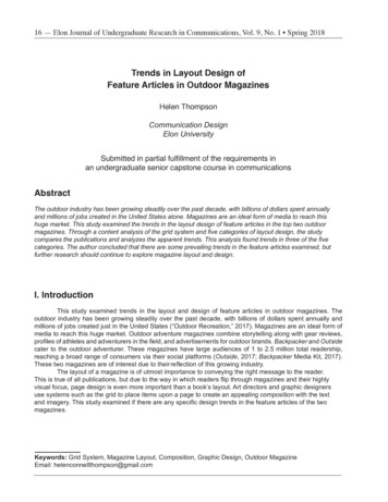
Electrical Design-inOperating windowLED technology is rapidly evolving. Using more efficientLEDs in a next generation means the same light outputcan be achieved with lower currents. At the same time,LEDs can be driven at different currents levels based onthe application requirement. Typically, LED drivers areavailable in discrete current levels e.g. 350mA, 500mAor 700mA. It is often necessary to replace a driver whenmore efficient LEDs or different LED boards becomeavailable.Output voltage [V]2505200131504100250000.10.20.30.40.5Output current [A]1.2.3.4.5.Required set point for the LED solutionCurrent can be set to needs within rangeDriver adapts to required voltage, given it fits rangeDriver minimum power limitDriver maximum power limitExample Operating window of a Xitanium driverNote: by means of dimming it is possible to go below theminimum value of the specified output current.One of the key features of the Xitanium LED drivers isthe adjustable output current (AOC), offering flexibilityand future-proof luminaire design. The Xitanium driverscan operate in a certain “operating window”. Thiswindow is defined by the maximum and minimumvoltage and current that the driver can handle. Anexample of an operating window is shown on theleft. The area indicates the possible current /voltagecombinations. The current you select will depend on thetype and manufacturer of the LEDs or the specific LEDconfiguration of the PCB design. The voltage is the sumof the LEDs used (total Vf string). The operating windowof every driver can be found in the datasheets which canbe downloaded on following website:www.philips.com/technology1. Drivers with SimpleSet functionality can beconfigured using the Philips MultiOne software andSimpleSet interface.2. DALI driver versions can be programmed both viaSimpleSet and DALI interface. More information canbe obtained at www.philips.com/multiOne.Note: by means of testing the accuracy of the outputcurrent, the condition is required as below:o Iout tolerance 5% @Ta 25 C istested @ 0 hour (cold start) Warning: Iout may have 20mA shift accordingto different Tc.June, 2016Design-in guide - Philips Xitanium Outdoor LED drivers11
* Note: when connecting Philips LED Lines to the driver, the typeof LED board (LV or HV) determines this requirement. HybridLED boards can be used on both type of drivers, indicated incommercial leaflet LED Lines, to be found in the downloadHow to Select an appropriate driverDepending on you requirements several drivers canbe found as a solution for you. The following stepscan help selecting the preferred driver.section of www.philips.com/technology** Note: for Philips LED Lines standard system configurations,driven at nominal current, are stated in the commercialleaflet LED Lines, to be found in the download section ofwww.philips.com/technologyNote: for a HV scenario that allows a 2 chain parallel solution, youare likely to find with steps described a lower rated driver power(e.g. 75 W for 1 chain versus 36 W for 2 chain solution)For a full overview of available driver models, pleaserefer to the commercial leaflet Xitanium Outdoor LEDdrivers, to be found in the download section ofwww.philips.com/technology, as are the datasheetsassociated with the drivers you intend to use.1. Determine your required drive current (Idrive) and voltage (Vf)2. Calculate required power via Pdrive Vf x Idrive (W)3. Determine which type* of driver do you need; Isolated orNon-isolated Collect the associated datasheets from thewebsite.4. Does required current fit current range of driver?- Idriver minimum Idrive Idriver maximum?5. Does required voltage fit voltage range of driver?- Vdriver minimum Vf Vdriver maximum?6. Does required power fit power range of driver?- Pdriver minimum Pdrive Pdriver maximum?7. Choose your type** of dimmingDriver wiring and pinningDriver lead wires with corresponding functions can be seen infigures on the left. The function of each wire will be discussedfurther in detail in the following chapters.NTC (thermal derating)LED module settingNote: currently all the Xitanium Outdoor LED drivers are singlechannel drivers. This means that for drivers with a double “ ” and“-“ output (see figure on the left) that these outputs are simplyin parallel.Signal groundXitanium driverSchematically representation of the drivers' output interfaces12Design-in guide - Philips Xitanium Outdoor LED driversJune, 2016
Adjustable Output Current (AOC) –set the driveroutput currentOutput current can be set by placing an externalresistor (LEDset and Rset) into the driver’s Rset input. Next tothat DALI driver versions allow also setting of the output currentvia software configuration.Note: Rset is used as generic indication for Rset1,Rset2 or LEDset.Note: LEDset and Rset-interface are not meant to beused as a control or dimming interface(for instance 1.10 V). If this is not observed, bothperformance and safety requirements of theinstallation may be affected.How to Determine AOC priority with LED driversSince the DALI drivers allow two methods to set theoutput current (AOC), it is good to take note of thepriority of each method with respect to the other.Historically there are two groups of DALI drivers; thosewhich can dim down to 1% (newer) and those whichcan dim down to 10% (older).Group 1: 10% minimum dim level (newer drivers)AOC programming has priority over Rset. For thepriority selection criteria see table on the left.Priority selection citeria for Group 1 - 1% minimum dim levelGroup 2: 1% minimum dim level (older drivers, 5% or10% minimum dim level)The value that sets the lowest current has priorityover the other.1. Iprogramming IRset ? priority for Iprogramming2. IRset Iprogramming ? priority for IRsetE.g. programming 200 mA has priority over Rsetwhich would generate 250 mA.And Rset that generates 200 mA has priority overprogramming 250 mA.Note: default current is stated in the driver’sdatasheet in the download section onwww.philips.com/technology.June, 2016Design-in guide - Philips Xitanium Outdoor LED drivers13
How to Set the output current via RsetExample of a Set’n’drive resistor featured by BJB, fittedwith a leaded resistor inside and allowing both manualor robot placementYour lumen, your current1 resistor value generates 1 current only at all window drivers aslong as it fits within the driver window.That is 1 philosophy for all window drivers.Why a resistor?a) Worldwide standardized building blockb) Worldwide availability and well documentedc) Freedom for OEM to choose the value and supplierResistor placed into driver enables you to1. Connect different configurations, not just a unique solution2. Drive different type of LED boards, not restricted to one type3. Select and tune the current, hence flux or TcResistor characteristicsBy making use of a resistor component with a determined Ohmvalue you can set the required current for your LED module. Thiscomponent can be a leaded standard 1% tolerance resistor of e.g.0.125 W or 0.25 W, 50 V. Rset will not be part of the electricalchain driving the LEDs, meaning it does not dissipate power.However, make sure it does not come into contact with thedriver’s housing. For safety reasons with non-isolated drivers theresistor must be insulated. Advice is to always insulate the resistor.Examples of a resistor placed into the drivers’ input is shown onthe left.2 different Rset resistors are utilized in the Xitaniumprogrammable LED driver portfolio; Rset1 (older drivers); allows output current settingup to 700 mA Rset2; allows output current setting up to 2000 mAIn all documentation, Rset may refer to either Rset1 or Rset2,depending on the driver type. Please check the driver datasheetfor which Rset (1 and/or 2) the driver you use reads.Note: While inserting the resistor, please refer to the imageon the left. The resistor must be inserted such that there is nopossibility of a short caused by the leads. Especially when usingnon-isolated drivers, make sure the leads of the resistor areinsulated. This way they cannot generate a potential safety risk,nor can the trip the earth leakage circuit breaker.14Design-in guide - Philips Xitanium Outdoor LED driversJune, 2016
Rset1 and Rset2 use different pins on the driverThe Rset1 and Rset2 values with the corresponding drivecurrents are shown in following tables. It is advised to select thenearest lower resistor value that is available to you, if the exactdetermined value is not at hand.How to Set the output current via LEDsetRset 1 and Rset 2 have been the traditional ways to set thecurrent in the Xitanium window drivers. Next generation driverswill now be introduced with LEDset. LEDset is introducedby several vendors in the market to provide an industrystandardized Rset interface. LEDset is, in essence, like Rset1 andRset2, where one resistor value leads to one output currentvalue only, differing only in the look-up table. Please find the tablefor E96 resistor values in the next section.Rset resistor mounted directly onto the driverWhat does LEDset offerLike Rset1 and Rset2, LEDset is an analogue interface, allowingbasic current setting. The interface supports the followingfunctions: Output current setting of the constant current LEDdriver to LED modules Thermal protection of the LED module(s) via thermaldynamic resistors circuitRset resistor mounted onto the LED moduleJune, 2016How does LEDset workLEDset is based on a 3 wire connection between LED driverand one or more LED modules as shown in the figure on theleft. Only one additional wire, besides the two LED currentsupply wires, is used for transferring information from the LEDmodule(s) to the LED driver, provided the Rset is mounted onthe LED module.Alternatively a standard resistor can be put directly into thedriver’s LEDset input connectors.Design-in guide - Philips Xitanium Outdoor LED drivers15
The LEDset interface measures the current Iset which flows froma 5V constant voltage source within the LED driver through thesetting resistor(s) Rset which is/are located either on the LEDmodules or directly into the driver’s Rset-input.The current Iset flowing through one setting resistorRset is determined by the equation:Iset [A] 5 [V] / Rset [Ω]A LED driver with LEDset interface is able to measure Iset andto set the LED driver output current Idrive dependent on themeasured value of Iset according to the equationIdrive Iset x 1000 [A]Therefore the overall relationship between the setting resistorand the LED driver output current Idrive is then given byIdrive [A] (5 [V] / Rset [Ω]) x 1000To calculate the required resistor value for a desired drive currentIdrive use:Rset [Ω] (5 [V] / Idrive [A]) x 1000The LEDset interface is intended to cover a LED driver outputcurrent range from 0.05 A to 8 A. The corresponding resistorRset is therefore within the range 100 kOhm to 625 Ohm.In addition, it is possible to add an over temperature protectioncircuit on the LED module which decreases the setting current incase of an over temperature event and thus limits or folds backthe LED driver output current.16Design-in guide - Philips Xitanium Outdoor LED driversJune, 2016
June, 2016Design-in guide - Philips Xitanium Outdoor LED drivers17
18Design-in guide - Philips Xitanium Outdoor LED driversJune, 2016
June, 2016Design-in guide - Philips Xitanium Outdoor LED drivers19
How to Program the output current1 interface – connecting to indoor & outdoor,LED & conventionalThe Xitanium Programmable drivers offer a full range of controls,enabling customizable luminaire design and performance.It is possible to control light output levels, preset dimmingprotocols and set system specifications in the factory and evenin the complete installations in the field. This can be done withthe Philips MultiOne configurator software. The MultiOneconfigurator software is an intuitive tool that unlocks the fullpotential of all programmable drivers from Philips, ensuringthat the driver performance matches the needs of the lightingsolution. It offers unprecedented flexibility, before, during andafter the product installation.Connecting to a programmable driverXitanium Programmable LED drivers are programmed via thePhilips MultiOne configurator software. To do so, the drivermust be connected to the computer via the MultiOne hardwareinterface.For more information and latest version please visitwww.philips.com/multione.This site contains detailed information on how to install thesoftware and how to program the driver.Mains voltage fluctuationsThe driver is able to withstand high and low mains voltages forlimited periods of time.Allowable voltage difference between mains inputand control input (LED version)The majority of our LED-drivers do comply with a voltageisolation difference up to 250V between mains and the Touchand Dim control input, as can be caused by a different phase ofthe power grid in an installation in the field.Future drivers might have a value higher than 250 V by design.Use of LineSwitch in three-phase power 230/400V gridsThe Xitanium Xtreme drivers allow for supplying power fromanother phase than the one controlling the LineSwitchinterface20Design-in guide - Philips Xitanium Outdoor LED driversJune, 2016
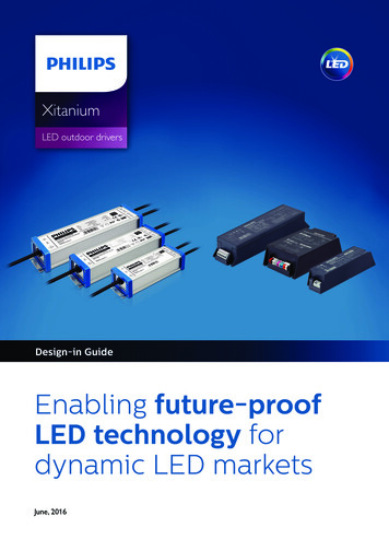
Low mains voltageA continuous low AC voltage ( 202 V) can have an adverseeffect on the driver’s lifetime. The output power will be limitedaccordingly. A low voltage will not cause the driver to fail over amaximum period of 48 hours at minimum operating AC voltageand maximum ballast ambient temperature.High mains voltageA high mains AC voltage will stress the driver and have anadverse effect on its lifetime (maximum of 264-305 V for aperiod of 48 hours).Inrush current‘Inrush current’ refers to the briefly occurring high input currentwhich flows into the driver during the initial start-up to chargethe capacitors on the input side. Typically, the amplitude is muchgreater than the operating or steady-state current, as illustrated.Graphical representation of inrush currentThe experimental setup for measuring the inrush current of theXitanium LED Programmable driver is shown. For the test setup,a line impedance of 645 mΩ / 22 μH (nom values) is used (NEMA410 standard requires a line impedance comprised of 450 mΩ /100 μH for inrush current measurement). For the measurements,an input DC voltage equal to the peak of the corresponding linevoltage is applied (via the capacitor bank).On a system with an ABB S261 B16 miniature circuit breaker, upto a maximum certain number of Xitanium LED programmabledrivers can be connected in parallel without the miniature circuitbreaker tripping at driver turn-on. The exact maximum numbercan be found in the applicable driver datasheet. Please notethat the inrush current does not increase proportionally withthe number of drivers connected in parallel; i.e. for “N” driversconnected in parallel does not equal “N” times the inrush currentfor one driver.June, 2016Design-in guide - Philips Xitanium Outdoor LED drivers21
MCB typeRating (A)Relative number of LED drivers (%)B16100 (stated i n datasheet)B1063B13 81B20125B25156C16170C10104C13135C20208C25260L, I 16108L, I 1065G, U, II 16212G, U, II 10127K, III 16254K, III 10154Conversion Table for maximum number of drivers on Differenttypes of Miniature Circuit Breakers.22How to Determine the number of drivers on a MCBThe maximum amount of drivers on a 16A type B MiniatureCircuit Breaker (MCB) is stated in the driver’s datasheet onwww.philips.com/technology.In the conversion table on the left that stated amount is used asreference (100%).The maximum quantity of drivers on different types of MCB canbe calculated by the reference (see driver’s datasheet) x Relativenumber (last column).Example;If datasheet states: max number on type B, 16 A 20,then for type C, 13 A the value will be 20 x 135% 27.Notes1. Data is based on a mains supply with an impedance of 400mΩ (equal to 15 m of 2.5 mm2 cable and another 20 mto the middle of the power distribution) in the worst-casescenario. With an impedance of 800 m2 the number ofdrivers can be increased by 10%.2. Measurements will be verified in real installations; data istherefore subject to change.3. In some cases the maximum number of drivers is notdetermined by the MCB but by the maximum electrical loadof the installation.4. Note that the maximum number of drivers is given whenthese are all switched on at the same time, e.g. by a wallswitch.5. Measurements were carried out on a single-pole MCB. Formultiple MCBs it is advisable to reduce the number of driversby 20%.6. The maximum number of drivers that can be connected toone 30 mA Residential Current Detector is 30.Design-in guide - Philips Xitanium Outdoor LED driversJune, 2016
Surge protectionThe challenge for Outdoor lightingOutdoor lighting systems are used in various types of applications,such as street and road lighting, parking areas and tunnels. Inmany of these installations there is a risk of extreme surges(e.g. lightning strikes). A direct hit will most likely destroy thecomponents in a luminaire. Even an indirect hit near the lightinginstallation might cause severe damage.External SPD offers the maximum protection for Outdoor LEDinvestmentsPole-mounted roadway lighting would typically fall into the moresevere High Exposure location.In C62.41.2 standard, for Location Category C (outside, serviceentrance and equipment), a protection level of 10 kV or more isrequired. There is almost no way to make the luminaire systemsurviving without any extra protection.Installing an external SPD can offer the maximum protection forOutdoor LED luminaire.Standard testeExposureExample of SPDLowHighOptional teste100 kHz Ring Wave forfront-of-wave responseevaluation3 kA310 kASurge Protection Devices (SPDs) intended for Location CategoryCLeakage currentThe Xitanium Outdoor LED drivers are designed to meet touchcurrent requirements per IEC 61347-1 standard. The specifiedmaximum values are 0.7 mA peak for IEC and 0.75 mA RMS forUL norms. The test is done with the driver alone. In a luminaire,touch current may be higher, since the LED load may introduceadditional touch current.Precautions may be required on the luminaire level and if multipledrivers are used in a single luminaire.June, 2016Design-in guide - Philips Xitanium Outdoor LED drivers23
Electromagnetic compatibility (EMC)Electromagnetic compatibility (EMC) is the ability of a deviceor system to operate satisfactorily in its electromagneticenvironment without causing unacceptable interference inpractical situations. Xitanium Outdoor LED drivers meet EMCrequirements per CISPR15 ed 7.2. This test is conducted with areference setup that includes a driver and an LED load/heat sinkcombination mounted on a metal plate.Keeping the wires close togetherKeep mains separated from the output wiresDo not route any wiring over and/or along thedriver enclosure24Improvement in EMI PerformanceThe following practical precautions need to be taken intoaccount in a lighting system to minimize EMI: Minimize the differential mode loop area of the lamp wiresgoing from the driver to the light source by keeping the wiresclose together (bundling). This will minimize the magnetic fieldand reduce the radiated EMI. Long linear light sources are alsopart of that loop. Minimize the common mode parasitic capacitance of theoutput wiring light source to earth by keeping the lengthof the wires between driver and light sour
June, 2016 Design-in guide - Philips Xitanium Outdoor LED drivers 7 Introduction Xitanium Outdoor LED drivers are designed to operate LED solutions for outdoor lighting applications such as flood, street, road lighting as well as open area environments. The operating points are