Transcription
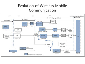
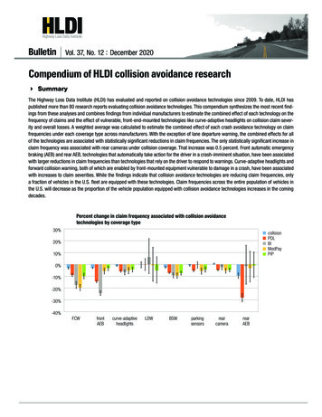
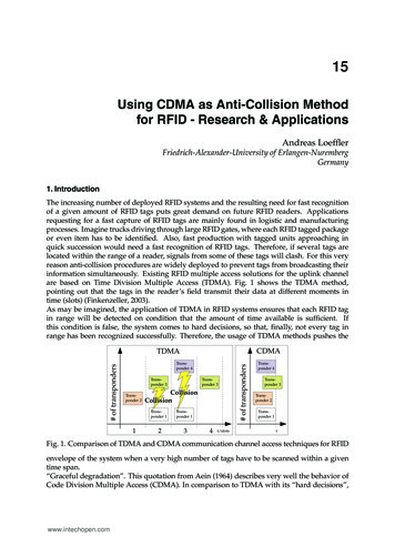
015Using CDMA as Anti-Collision Methodfor RFID - Research & ApplicationsAndreas LoefflerFriedrich-Alexander-University of Erlangen-NurembergGermany1. IntroductionThe increasing number of deployed RFID systems and the resulting need for fast recognitionof a given amount of RFID tags puts great demand on future RFID readers. Applicationsrequesting for a fast capture of RFID tags are mainly found in logistic and manufacturingprocesses. Imagine trucks driving through large RFID gates, where each RFID tagged packageor even item has to be identified. Also, fast production with tagged units approaching inquick succession would need a fast recognition of RFID tags. Therefore, if several tags arelocated within the range of a reader, signals from some of these tags will clash. For this veryreason anti-collision procedures are widely deployed to prevent tags from broadcasting theirinformation simultaneously. Existing RFID multiple access solutions for the uplink channelare based on Time Division Multiple Access (TDMA). Fig. 1 shows the TDMA method,pointing out that the tags in the reader’s field transmit their data at different moments intime (slots) (Finkenzeller, 2003).As may be imagined, the application of TDMA in RFID systems ensures that each RFID tagin range will be detected on condition that the amount of time available is sufficient. Ifthis condition is false, the system comes to hard decisions, so that, finally, not every tag inrange has been recognized successfully. Therefore, the usage of TDMA methods pushes theCDMATransponder 4Transponder 3Transponder 3Transponder 21CollisionCollisionTransponder 1Transponder 1234t/slots# of transponders# of transpondersTDMATransponder 4Transponder 3Transponder 2Transponder 1tFig. 1. Comparison of TDMA and CDMA communication channel access techniques for RFIDenvelope of the system when a very high number of tags have to be scanned within a giventime span.“Graceful degradation”. This quotation from Aein (1964) describes very well the behavior ofCode Division Multiple Access (CDMA). In comparison to TDMA with its “hard decisions”,www.intechopen.com
3062Current Trends and Challengesin RFIDWill-be-set-by-IN-TECHCDMA-based systems take “soft decisions”, which means, that within the system eachadditionally introduced RFID tag decreases the overall probability of detection of all tags.However, for a particular amount of tags, the system may be optimized in such a way thatthe time needed for detection may be minimized. Therefore, for an RFID system underthose certain circumstances, the introduction of CDMA may offer a way out (Fig. 1). Thetransponders, each equipped with a unique quasi-orthogonal spreading code (e.g., Goldcodes (Gold, 1967a)), may use the radio channel whenever the transponders are ready totransmit their data (asynchronous CDMA). The objective is the realization of a DS (directsequence)-CDMA-based RFID system using semi-passive UHF transponders, with the readerproviding the recognition of multiple transponders simultaneously. This means that thetransponders are transmitting data within the same time range and frequency band, incontrast to the existing systems based on TDMA.The realized UHF transponders operate in semi-passive mode, meaning that the digital partof the transponder, i.e., the data generation, has an active power supply, whereas the highfrequency (HF) part works in passive mode taking advantage of the backscatter principle.The attendant RFID reader, though, is separated into two parts. Part one, described astransmitting system, generates a carrier wave at around 867 MHz. Part two, the receivingsystem, mainly demodulates the incoming backscattered signals of the RFID tags.This chapter is organized in seven sections. The first section gives a brief introduction tothe topic of anti-collision in UHF-RFID-based systems. The following sections introduceCDMA by outlining the advantages over the current used TDMA schemes. After introducingparticular problems backscattering RFID systems have to deal with, a concept and animplementation of such a CDMA-based RFID system is shown. The chapter ends with variousmeasurements concerning the system and subsequent results.2. Anti-collision: EPC class 1 Gen 2This section outlines some basic issues regarding anti-collision methods within RFID. Basicand state-of-the-art anti-collision methods are shown in Subsection 2.1. Subsection 2.2presents theoretical performance issues regarding the throughput by comparingstate-of-the-art TDMA methods with CDMA anti-collision methods.2.1 ALOHA and slotted ALOHABefore elucidating the state-of-the-art anti-collision method for UHF RFID systems, theprinciple of ALOHA and unslotted ALOHA (Bertsekas & Gallager, 1992) is illustrated, as theprinciple of ALOHA provides the basis for the modern anti-collision protocols. The ALOHAprotocol (or pure ALOHA), first published by Abramson (1970), is a very simple transmissionprotocol. The transmitter sends its data, no matter if the transmission channel is free ornot. This means the transmitter does not care about collisions with other transmitters. Thetransmitter resends its data later, if the acknowledgment from the receiver is missing. RFIDsystems based on the principle of pure ALOHA are, e.g., based on the TTF principle, i.e.,transponder-talks-first. The IPX protocol from IPICO (2009) is an example for RFID systemsusing unslotted or pure ALOHA.An extension of the ALOHA protocol, called slotted ALOHA (Roberts, 1975) introduces timeslots in which the transmitter must send its data at the beginning. Therefore, collisionsonly occur within a full time slot. This extension doubles the maximum throughput of thesystem. Most current RFID protocols are based on the principle of slotted ALOHA, as isalso the very commonly used EPC standard UHF Class-1 Generation-2 air interface protocolwww.intechopen.com
Using CDMA as Anti-Collision MethodUsingCDMA& Applicationsas Anti-Collision Method for RFID - Research & Applicationsfor RFID - Research3073V1.2.0 (ISO 18000-6C), commonly known as “Gen2”. Basically, the “Gen2” standard defines,that every communication is triggered by the RFID reader, i.e., RTF (reader-talks-first). Aninventory round, i.e., the process of detecting all available transponders, is started with theQuery-command to acquire all transponders available in the read range. This commandinherits a so called Q-parameter. Using this Q-parameter, every transponder generates arandom number RN in the range [0; 2Q 1] and initializes its internal slot counter withthis random number. If, at a given moment, the value of the slot counter of one or moretransponders equals 0, the transponders send a 16 bit random number called RN16 . Afterthe acknowledgment of the RN16 through the reader, the electronic product code (EPC)is transmitted from the transponder to the reader and the transponder will be marked asinventoried. All the left-over (non-marked) transponders are prompted to decrement its slotcounter by sending a QueryRep-command, and the procedure starts all over again. In the caseof several transponders initializing their slot counters with the same random number RN, itwill come sooner or later to a signal collision as the slot counters will reach zero at the sametime slot. If the reader recognizes such a collision, another inventory round will be initiatedto identify the left-over transponders. Therefore, a newly value of Q will be introduced andnew random numbers will be calculated. To sum up, one could say that the choice of Q is atypical trade-off. Choosing a high Q will lead to a smaller number of collisions, at the expenseof an increasing time needed for an inventory round. Indeed, a smaller Q will lead to lessacquisition time, but to more collisions.Plenty of work has been done to improve the current EPC standard. Improving the currentstandard anti-collision method by choosing an appropriate value of Q, e.g., dynamically, isdescribed in Maguire & Pappu (2009); Pupunwiwat & Stantic (2010); Wang & Liu (2006). Theright choice of Q is of great importance for the overall system performance, so that an accurateestimation would improve the time needed for an inventory round. Slightly new algorithms,based on the current EPC “Gen2” standard are outlined, e.g, in Cui & Zhao (2009); Lee et al.(2008). New better performing algorithms for the slotted ALOHA protocol for RFID aredescribed in Bang et al. (2009); Choi et al. (2007); Liu et al. (2009); Makwimanloy et al. (2009).A complete new system with time hopping on the communication link from tag to reader isoutlined in Zhang et al. (2010).2.2 Comparison: CDMA versus TDMA in UHF-RFIDThe throughput S in dependence of the traffic channel rate G describes the performance ofa given transmission system regarding how many packets must be transmitted (statistically)until a successful transmission occurs. This statement is given with the term GS as describedS defines accordingly theby Kleinrock & Tobagi (1975). The reciprocal of this term, i.e., Gprobability of a successful transmission. The channel capacity is determined by maximizing Swith respect to G (Kleinrock & Tobagi, 1975). According to Abramson (1970) the pure ALOHAtransmission has a relation between S and G ofS G e G(1), whereas the throughput of the slotted ALOHA transmission is defined after Roberts (1975)withS G e 2G(2)1 18.4% for pure ALOHA and 1 36.8%. Accordingly, the maximum channel capacity is 2eefor slotted ALOHA.For a fair comparison between CDMA-based systems and ALOHA systems, the totalwww.intechopen.com
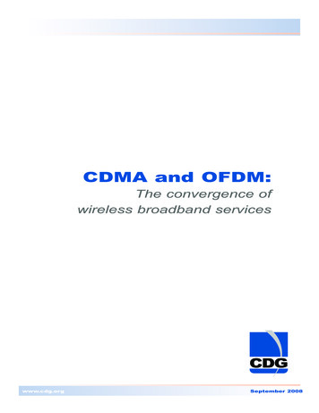
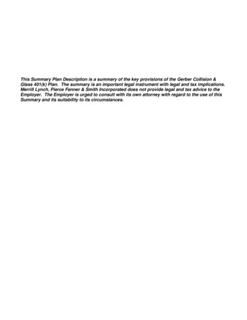
308Current Trends and Challengesin RFIDWill-be-set-by-IN-TECH4ALOHAslotted ALOHACDMA (C 1)CDMA (C 5)CDMA (C 10).5Throughput S.4.368.3.184.100.5 .73 11.522.533.54Traffic rate GFig. 2. Various throughputs S over traffic rate G for ALOHA, slotted ALOHA and CDMAbandwidth has to be maintained the same for both systems. A CDMA system has aso called spreading factor C, which is proportional to the length of the spreading codesrespectively the ratio between chip rate and bit rate (i.e., Rchip /Rbit ) used. According toLinnartz & Vvedenskaya (2009) the throughput S and the offered traffic rate G isS G e CGC 1 k 0(CG )k.k!(3)Setting C 1 leads to the slotted ALOHA transmission scheme. Figure 2 shows variousthroughputs S over the traffic rate G. The figure shows the throughputs for ALOHA (channelcapacity 18.4%), slotted ALOHA and CDMA with spreading factor C 1 (channel capacity36.8%), CDMA with C 5 (channel capacity 50.87%) and CDMA with C 10 (channelcapacity 58.31%). This graph shows the basic difference between TDMA (ALOHA-based)and CDMA systems. In general, TDMA-based RFID systems can handle much more RFIDtransponders with a lower overall throughput. CDMA-based system, on the other hand, areable to handle a limited amount of RFID tags with higher overall throughput. For instance,assuming a limited amount of RFID transponders for a traffic rate G 0.73. The throughputof unslotted ALOHA would be SALOHA 16.95% and the throughput of slotted ALOHASunslotted ALOHA 35.18%. A CDMA-based system with a spreading factor C of 10 wouldhave there its maximum throughput of SCDMA,C 10 58.31%. This scenario is shown inFigure 2.Finally, it can be stated that CDMA-based RFID systems may be better for particularapplications, in which the number of transponders is limited and the inventory process has tobe made very fast, e.g., fast production lines and automation processes.Particular slotted ALOHA CDMA systems and corresponding performances may be found inGopalan et al. (2005); Sakata et al. (2007). Other works describe certain CDMA systems witherror correction which really outperform the TDMA-based systems. Examples can be foundin Liu et al. (2001); Liu & El Zarki (1994); Lo et al. (1996); Sastry (1984); van Nee et al. (1995).Also this list is not complete it gives a short overview of CDMA-based system performances.www.intechopen.com
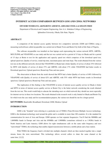
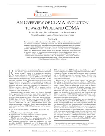
Using CDMA as Anti-Collision Method3095UsingCDMA& Applicationsas Anti-Collision Method for RFID - Research & Applicationsfor RFID - ResearchTX1Tage1CodTX pathDataTag 2Code 2ControlDataRX pathRXRFID readerTagnCodenFig. 3. Basic architecture of RFID system; depicted in monostatic antenna configuration3. Concept of CDMA-based systemThis section presents the basics of the proposed RFID system. Going into more detail,Subsection 4.1 shows the architecture of the Transmitting System (TX system path)followed by Subsection 4.2 presenting the proposed semi-passive RFID transponders andSubsection 4.3 describing the Receiving System (RX system path).Figure 3 shows the basic architecture of the CDMA-based RFID system. Generally, it consists,as any other RFID system of two major parts. First, the RFID reader itself and second, one ormore transponders. The main difference between this system and other current systems is thechannel access method in the uplink (transponder to reader communication) layer, in this casebased on CDMA; this fact is illustrated in Figure 3 showing each transponder (Transponder 1to Transponder n) with a unique spreading code (Code 1 to Code n).The basic working principle is also indicted in Figure 3, showing the RFID reader transmittinga sinusoidal wave over its transmit antenna TX, thus allowing the various transponders in thefield to modulate and reflect (principle of backscatter) this incident wave back to the RFIDreader. Therefore, the total backscattered signal consists of the additive superposition of n(if multipath is negligible) backscattered transponder signals with each transponder usingits own unique spreading code. Receiving this superimposed signal over RX, the readeris, generally, able to separate the various transponder signals from each other (process ofdespreading) in order to restore the transponders’ data.Figure 3 and Figure 5, respectively, show the concept and the architecture of the realized RFIDreader. The following paragraphs will refer to these figures. Fig. 6 shows the setup of thesystem for directly measuring the backscattered baseband signals.4. ImplementationWithin this section, the implementation of the CDMA-based RFID system is described. Byreferring to Figure 4 and 5, Subsection 4.1 describes the overall TX path, involving thePLL-based RF synthesizer, a power amplifier (PA) and the TX antenna, whereas Subsection 4.3reveals the fundamentals of the RX path, consisting of RX antenna, low-noise amplifier (LNA),a demodulator module, a baseband processing unit, a baseband sampling module (ADCmodule) and a subsequent DSP module for evaluating the incoming data. However, the basicsof the transponder are depicted in Subsection 4.2.www.intechopen.com
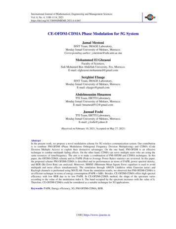
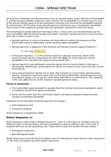
310Current Trends and Challengesin RFIDWill-be-set-by-IN-TECH6ComputerRFID reader TXUSB RF synthesizer PAUARTDSPMicrocontrollerDSP moduleBase moduleSPIPLLRXIADCQADC moduleAnalog ulator moduleFig. 4. Basic concept of RFID reader; depicted in bistatic antenna configuration4.1 TX system pathThe proposed semi-passive UHF transponder works in accordance with the principle ofbackscattering. The incident wave to be backscattered is generated by the Transmitting System.Considering the RFID uplink channel (tag to reader), the introduced Transmitting System(see Figure 3 and Figure 5) consists of a PLL-based RF synthesizer (Figure 3 and Figure 5), generating a sine wave (here with f carrier 866.5 MHz, maximum output power Pout 1 dBm at 50 Ω), an upstream power amplifier (PA, Gain GPA 20 dB, 1 dB compressionpoint 24 dBm), and a linear polarized 50 Ω antenna (TX, Gain GTX 7 dBi). The purposeof the transmitter is to generate an RF wave to be reflected (backscattered) by the UHFtransponder whereby the reflected wave is received by the Receiving System further discussedin Subsection 4.3.It has to be mentioned that the RF synthesizer not only generates a sine wave for thetransmitting part, but also for the receiving part of the system. Indeed, it is used as localoscillator (LO) source for the downmixing part of the receiver. However, both synthesized RFwaves inherit the same frequency as they are both created by the same PLL; the waves onlydiffer in π in phase.4.2 TransponderThe major tasks of the semi-passive UHF transponders are: Generate spreading code Create spreaded datawww.intechopen.com
Using CDMA as Anti-Collision Method3117UsingCDMA& Applicationsas Anti-Collision Method for RFID - Research & Applicationsfor RFID - ResearchRXTXDemodulator moduleLNAAnalog baseband processing modulePAADC moduleRF synthesizerBase moduleDSP moduleFig. 5. Architecture of CDMA-based RFID reader Modulate and reflect incoming RF signal at f carrier 866.5 MHz (principle of backscatter)Figure 7 shows the basic principle of an RFID transponder. An incident RF wave is reflectedby the transponder. The phase and amplitude of the reflected wave is affected by threemajor issues: The first two issues includee structural mode and antenna mode scattering(Hansen, 1989; Penttila et al., 2006), the third issue is the multipath propagation. Multipatheffects are a non-changeable fact, so they can be neglected at this point. The structural modescattering of an antenna is dependent on the structure of the antenna itself (material, antennageometry, etc.) and cannot be changed - therefore, the structural mode may not be used fora normal data transmission. The antenna mode scattering, on the other hand, describes thereceiving and emitting effects of an antenna, which usually depend on the impedances used;particularly the impedance of the antenna Zant itself and the corresponding load impedanceZload of the following transponder system. Assuming that Zload can adopt two values beingZ1 and Z2 . According to Figure 7 the antenna mode scattering may be changed by alteringthe load impedance Zload of the transponder’s antenna according to the data the transponderwww.intechopen.com
312Current Trends and Challengesin ulatorµCRFIDtagRX inRXantennaI, Q outDemodulator Baseband processorLO inTX sourceLO sourceLNAFig. 6. Setup of CDMA-based UHF-RFID system with a magnification of the oscilloscope’sscreenRF erBackscattered / reflected waveFig. 7. Basic function of RFID transponderwants to send. Binary data may be send by altering Zload between Z1 and Z2 , thus changingthe reflection coefficient between Zant and Zload, which in turn leads to an alteration of thereflection of the RF wave in phase and/or amplitude. Again, this only affects the antennamode scattering. However, the total resulting backscattered signal is the superposition ofthe multipath signal, the structural mode scattering and antenna mode scattering effects.Measurements at the end of this paper will show this effects.Figure 8 shows the basic concept of the CDMA-based semi-passive transponder. A centralmicrocontroller generates the binary output data stream (i.e., the already coded and spreadeduser data) to drive the fast RF switch ’S’, that alters between two impedance states Z1 and Z2 ;according to the binary state of the output data stream, a logical ’1’ triggers Z2 , a logical ’0’triggers Z1 to be the corresponding load impedance. Therefore, the data stream directly affectsthe reflection coefficient. The performance of the uplink (tag to reader radio channel) dependswww.intechopen.com
Using CDMA as Anti-Collision Methodfor RFID - Research & Applications9very much on the modulation efficiency ηmod of the backscatter modulator (Fuschini et al.,2008; Karthaus & Fischer, 2003; Nikitin & Rao, 2008), which basic calculation is subject of thefollowing paragraph.Patch antennaZ1MicrocontrollerUser dataSpreading codeCodingSpreadingSZ2SPIModulatorTransponderFig. 8. Concept of CDMA-based semi-passive UHF RFID transponder4.2.1 Determining load ImpedancesAssuming an antenna with complex antenna impedanceZant R a j Xa(4)with R a Rr Rl as the sum of radiation resistance Rr and real antenna losses Rl , and Xa asthe imaginary part of the antenna impedance. The complex reflection coefficients Γ1,2 betweenthe antenna impedance and the load impedances Z1,2 can be described asΓ1,2 www.intechopen.com Z1,2 Zant
314Current Trends and Challengesin RFIDWill-be-set-by-IN-TECH10with U0 as the antenna’s open circuit voltage and a being the wave from the antennaimpedance to the load impedance (see Rembold (2009) for details).Maximum modulation efficiency ηmod is achieved when the difference of the complexreflections coefficients Γ1 and Γ2 is maximum. Supposing two vectors (Γ1 and Γ2 ) in a complexcoordinate system, the maximum difference between both vectors is achieved at the pointwhen the phase ϕΓ differs with π under the assumption that the maximum absolute value ofany Γ is limited to 1. That determines the complex reflection coefficients Γ1,2 toΓ1 e jϕΓ,1Γ2 e jϕΓ,1 jπ(9)(10)Setting ϕΓ,1 to 0 sets Γ1,2 to 1. According to Equation (5) this will define the load impedancesto ΓZant1,2 Zant1 Γ1,2(11) Z1 ZZantant 0(12) Z2 ZZant 2jXaant jXa22(13)Z1,2 The antenna designed for the RFID transponders is a 50 Ω patch antenna (Figure 10).Therefore the imaginary part (within the specified frequency range) Xa 0. This determinesZ2 jXa 0. A load impedance of Z1 corresponds to an open circuit wheresZ2 0 corresponds to a short circuit. Choosing open and short circuit states as desired loadimpedances, the maximum achievable modulation efficiency is, according to Equation (7),determined to be82ηmod 2 1 1 2 2 81%(14)ππIn order to have the maximum modulation efficiency for the CDMA-based RFID system, theload impedances of the realized semi-passive transponders are set to open and short circuit.By choosing these values as load impedances, one has to keep in mind, that this is onlyadvisable for semi-passive UHF RFID transponders. If passive transponders are designed, onehas to consider the power consumption into its calculations. Therefore, open and short circuitvalues are not suitable, as the backscattered power is, in fact, too high, as the transponderneeds a large portion of the incoming power for supplying itself (Dobkin, 2008).4.2.2 Transponder basicsFigure 9 illustrates the concept of the transponder and Figure 10 shows one of the realizedtransponders to achieve the previously mentioned tasks. The microcontroller (µC) is poweredby a power supply and may be user-controlled using USB or pushbuttons. The µC generatesthe unique spreading code and subsequently, the spreaded outgoing data. The data areforwarded to the SPI interface to drive the modulator of the transponder with differentinput voltages to adjust different load impedances respectively reflection coefficients of themodulator. The block diagram of the modulator (Figure 8) shows the principle of the proposedsimple backscatter modulator. An example on how to design load modulators can be found inPardo et al. (2007). However, the incoming spreaded data stream is low-pass filtered to limitwww.intechopen.com
Using CDMA as Anti-Collision Method31511UsingCDMA& Applicationsas Anti-Collision Method for RFID - Research & Applicationsfor RFID - Research TransponderMeasuring field strengthRSSITiny patchantenna Patch antennaEnergy supplyBackscattering dataADCSPIµCModulatorBase boardRF DividerTiny patchantennaI/ODividing RF frequencyFig. 9. Block diagram of semi-passive UHF RFID transponder with limited downlinkcapabilitiesthe outgoing bandwidth. As the modulator should be as simple as possible, an RF switch ’S’forms the interface between the logic data and the backscattered HF wave. The inputs of theswitch are driven by the spreaded data stream with two voltage levels (0 and 2.75 V) given bya buffer driver. One connection of the switch is linked to the patch antenna’s microstrip line(50 Ω); the ground connection is linked to the patch antennas ground plane. By triggering theswitch’s input with the spreaded data to be sent, either Z1 or Z2 is connected to the antenna.This modification changes in turn the reflection of an incident electromagnetic wave. Thedifference of phase and amplitude of the reflection is a direct indicator for the efficiency ofa backscattering modulator. As mentioned above the modulators load impedances are set toopen and short circuit to achieve maximum modulation efficiency. An exemplary spectralextract of the backscattered output of the transponder, measured at the receiving antenna, isgiven in Figure 17. On closer inspection, one can see the spreaded data (chip rate is 1.5 Mcps)around the carrier frequency (866.5 MHz). As these data signal levels (P 90 dBm 10 dB)are not very high, an accurate implementation of the receiving system becomes necessary.For a limited downlink (reader to tag) capability the transponders are equipped with a modulefor measuring the field strength (RSSI) and a module for measuring the frequency (RF Divider)of the incident RF wave emitted by the reader. The RF Divider is currently used to indicate thetransponder to send its data as soon as a carrier between 865 MHz and 868 MHz is detected.The RSSI module is used for statistical measurements. Anyway, both modules are not part ofthis work.www.intechopen.com
316Current Trends and Challengesin RFIDWill-be-set-by-IN-TECH12RSSIModulatorPatch antennaBase boardRF DividerFig. 10. Prototype of semi-passive UHF RFID transponderZ2 , e.g., short circuitRF switchZ1 , e.g., open circuitScreening shieldFig. 11. Backscatter modulator4.2.3 ModulatorThe transponder’s modulator is one of the key components of the system. Usually, it effectsthe energy supply (only for passive working transponders) and the modulation efficiency (forpassive and semi-passive working transponders) of transponders. Therefore, it has a directeffect for the maximum achievable range of such a system. The principle of the modulatorhas been already discussed above, so that this paragraph focuses primarily on the realization.Figure 11 shows the modulator, with and without RF shielding. The left part of the modulatoris connected to the transponder’s base board, the right SMA plug to the patch antenna asshown in Figure 10. The part within the RF shielding is responsible for the backscatteringeffects. A part of the incident RF wave is fed into the modulator. The part depends onthe antenna (structural and antenna mode) and the reflection coefficient between antennawww.intechopen.com
Using CDMA as Anti-Collision Method31713UsingCDMA& Applicationsas Anti-Collision Method for RFID - Research & Applicationsfor RFID - Researchimpedance Zant and the load impedance Zload of the connected modulator. This part is fedinto the RF switch and the load impedance (either Z1 or Z2 ), which corresponds to the currentstate of the switch. The state of the switch is defined by a buffered microcontroller output.which itself shows the current voltage of the binary data stream to be sent. In the case of Z1(open circuit state), the incident wave is entirely reflected with no phase shift. State Z2 (shortcircuit) also corresponds to a total reflection, but with a phase shift of 180 .Measuring the load impedances of the modulator show a very good accordance with thetheoretical results. Figure 12 shows the reflection coefficients within a Smith chart. As one cansee the phase difference is not exactly π. Z2 (short circuit) has nearly short circuit properties;Z2 (open circuit) has nearly open circuit properties. The frequency range of the measurementwas between 852 MHz and 882 MHz.1.00.52.05.0Short5.02.01.00.50 0.20.2 circuit 0.25.0Open circuit 2.00.51.0Fig. 12. Smith chart of modulator4.2.4 Gold codesThe choice of an appropriate set of spreading codes is a key issue when designing CDMAsystems. Gold codes seem to be one of the best codes to be used in UHF RFID systems.Mutti & Floerkemeier (2008), for instance, state that Gold codes outperform Kasami codes.Moreover, one Gold code family contains a large number of unique codes, which provides ahigh probability of finding a well-suited set of codes for a system to be designed.Gold codes, first introduced by Robert Gold (Gold, 1967b), are commonly used in spreadspectrum systems, such as WLAN and UMTS as well as in GPS (C/A code). The generationof Gold codes is quite simple as only two linear feedback shift registers (LFSR) are necessaryto create one set of codes. Other advantages of Gold code are: Good balance between auto- and cross-correlation Flexibility in code length No user synchronization necessary, i.e. the transponders need not to be synchronizedamong each otherBecause of above mentioned advantages, the proposed CDMA-based system uses Goldsequences.www.intechopen.com
318Current Trends and Challengesin RFIDWill-be-set-by-IN-TECH1412012010010080Φ22 ( τ )Φ11 ( τ )However, Gold codes have a length of 2m 1 with m being the order of each linear feedbackshift register. For reasons of flexibility a Gold code generator has been implemented onthe transponder’s 32 bit µC. The choice fell upon a Gold code length of 127 (m 7). Thecharacteristic polynomial is 137dec for the first LFSR and 143dec for the second one. Theinitial value for the first LFSR is 85dec . By choosing two Gold codes (Code 1 and Code 2)the second LFSR is initialized with 127dec for the first and with 111dec for the second code.Then, a small adjustment was made to the generated Gold codes to be more compatible to theµC. A succeeding binary ’0’ is added to each code to move it to a length of 128 bit. To showthe effect of this ’0’, the auto-correlation function (ACF) and cross-correlation function (CCF)have been evaluated for both Codes. Figure 13 shows the ACF Φ cc of the original 127 bit Goldcodes. Figure 14 illustrates the ACF Φ cc (τ ) of the adjusted (127 1 bit) Gold codes. The resultsare slightly higher values beyond the peak value at τ 0. As not only the auto-correlationcounts, the corresponding cross-correlation Φ12 (τ ) between the two codes are presented inFigure 15. As expec
A CDMA-based system with a spreading factor C of 10 would have there its maximum throughput of S CDMA, C 10 58.31%. This scenario is shown in Figure 2. Finally, it can be stated that CDMA-based RFID systems may be better for particular applications, in which the number of transpondersis limited and the inventory processhas to