Transcription
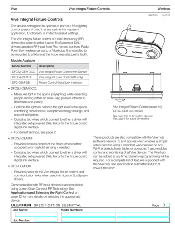
ViveVive Integral Fixture ControlsWireless3691039m 1 04.08.21Vive Integral Fixture ControlsThis device is designed to operate as part of a Vive lightingcontrol system. If used in a standalone (non-system)application, functionality is limited to default settings.The Vive integral fixture control is a radio frequency (RF)device that controls either Lutron EcoSystem or DALIdrivers based on RF input from Pico remote controls, RadioPowr Savr wireless sensors, or Vive hubs. It is intended tobe mounted to a fixture at the fixture manufacturer’s facility.Models AvailableModel NumberDescriptionDFCSJ-OEM-OCCVive Integral Fixture Control with SensorDFCSJ-OEM-RFVive Integral Fixture Control (RF only)DFC-OEM-DBIFixture Control Digital Link Interface DFCSJ-OEM-OCC:– M easures light in the space (daylighting) while detectingpeople moving within an area using passive infrared todetermine occupancy.– C ontrols the lights to balance the light level in the space,combining convenience, exceptional energy savings, andease of installation.– C ontains two wires which connect to either a driver withintegrated self-powered DALI link or to the fixture controldigital link interface.Vive Integral Fixture Control (scale 1:1)(DFCSJ-OEM-OCC shown)See page 9 & 10 for system diagramSee page 5 for actual dimensions– F or default settings, see page 2. DFCSJ-OEM-RF– P rovides wireless control of the fixture when neitheroccupancy nor daylight sensing is needed.– C ontains two wires which connect to either a driver withintegrated self-powered DALI link or to the fixture controldigital link interface. DFC-OEM-DBIThese products are also compatible with the Vive hub(software version 1.5 and above) which enables a simplesetup process using a standard web browser on anyWi-Fi enabled phone, tablet or computer. It also enablescontrol and monitoring of all Vive devices. The Vive hubcan be added at any time. System reprogramming will berequired. For a complete list of features supported withthe Vive hub, see specification submittal 369902 atwww.lutron.com– P rovides power to the Vive integral fixture control andcommunication links when used with Lutron EcoSystemdrivers.Communication with RF input devices is accomplishedusing Lutron Clear Connect RF Technology. SeeApplications and Selecting the Right Control onpage 12 for more details on selecting the appropriatedevice. Job Name:Job Number:S P E C I F I C AT I O N S U B M I T TA LModel Numbers:Page1
ViveVive Integral Fixture ControlsWireless3691039m 2 04.08.21SpecificationsVive Integral Fixture ControlsRegulatory Approvals cULus Listed (UL244A - listing E174075) Complies with requirements for use in other spaces usedfor environmental air (plenums) perNECR 2014 300.22(C)(3) FCC compliant with the limits for a Class Bdigital device IC (Industry Canada) C ontrols DALI-compliant loadsPower / Load IEC SELV / NECR Class 2 Operating voltage: 9.5–20.5 V Operating current: 250 mA max Connects to Lutron EcoSystem LED drivers, OSRAMRDEXALR drivers, or Advance XitaniumR SR drivers- See page 4 for maximum number of driversColors Available in White onlyEnvironmental Ambient operating temperature: 32 F to 131 F(0 C to 55 C), 0%–90% humidity, non-condensing;indoor use onlyWarranty 5 Year Limited Warranty. For additional Warrantyinformation, please 321.pdfMounting Vive integral fixture control mounts to a fixture (notintended for external / remote mounting).Frequency 431.0–437.0 MHz (U.S.A., Canada, Mexico)Range Wireless sensors and controls must be located within60 ft (18 m) from each other in the line of sight, or 30 ft(9 m) through walls. Devices must be located within 71 ft (22 m) of theVive hub. Utilizes Lutron Clear Connect RF TechnologyDefault Sensor Settings for DFCSJ-OEM-OCC(adjustable ONLY via the Vive hub user interfaceunless otherwise noted) Occupancy sensor timeout: 15 minutes Occupancy sensor sensitivity: Medium Mode: Occupancy detection (auto-ON, auto-OFF) Occupied light level: 100% (note this can also bechanged with a Pico remote and Radio Powr Savrsensor - see App Note #556 (048556) atwww.lutron.com) Daylighting: Enabled Daylighting dims lights to OFF from low light level whensufficient ambient light is present for 15 minutes or more.Wiring Wires: 600 V- rated, 18 AWG (0.75 mm2) solidcopper conductor Job Name:Job Number:S P E C I F I C AT I O N S U B M I T TA LModel Numbers:Page2
ViveVive Integral Fixture ControlsWireless3691039m 3 04.08.21Specifications (continued)Vive Integral Fixture Controls (continued)DFCSJ-OEM-OCC Features (these do not apply toDFCSJ-OEM-RF)Occupancy / Vacancy Functionality: Passive infrared motion detection with exclusive LutronXCT Technology for major and minor motion detection. 360 field-of-view. 144 ft2 (43.9 m2) major motion and minor motion coveragebased on 9 ft (2.75 m) ceiling height. See page 7 for moredetails.Daylight Sensor Functionality: Daylight sensor has simple, automatic calibrationout-of-the-box. Designed to give a linear response to changes inlight level. Detects ambient light level changes from 0 to 1600 lx(0 to 150 fc). Daylight compensation through Lutron reliable closedloop proportional control. For more information, tingwhite-paper.pdfFixture Level Settings(adjustable via the Vive hub user interface) Low-end trim adjustment (default is minimum levelfor Lutron EcoSystem drivers). Also adjustable usingPico wireless control. See App Note #556 (048556)at www.lutron.com High-end trim adjustment (default is 100% forLutron EcoSystem drivers). Also adjustable usingPico wireless control. See App Note #556 (048556)at www.lutron.com Minimum Light Level Setting (optional). Certainapplications, such as hallways, may require thatthe lights never turn off. For these areas, selectthe minimum light level option and the load willlower to programed low-end level. Favorite light level can be set using a Pico remotecontrol.DFCSJ-OEM-OCC/RF Features Power failure memory 2-wire connection between a Vive integral fixture control,an EcoSystem driver, and a fixture control digital linkinterface– The wires are non-polarized to prevent mis-wiresbetween the DALI terminals Measured power available when connected to a driverthat has that capability (such as Advance XitaniumR SRor OSRAMR DEXALT). Accuracy is defined by the driverspecification. Measured power uses power reported from the driver.Theoretical power requires the user to specify a maxpower value in the Vive app / UI, and calculates powerbased on the current load level. Job Name:Job Number:S P E C I F I C AT I O N S U B M I T TA LModel Numbers:Page3
ViveVive Integral Fixture ControlsWireless3691039m 4 04.08.21Specifications (continued)Compatible Drivers** (see 048642 for wiring diagrams)Model NumberDescriptionType of PowerReportingMaximumNumber ofDrivers*Notes/LimitationsOTi85 / 120-277/2A3 DX LOTi50 / 120-277/1A4 DX LOTi30 / 120-277/1A0 DX LOSRAMR DEXALTMeasured2– M ore than 2 drivers requires there-configuration of additional drivers tode-activate DALI power supply.– If more than 3 drivers are connected, thischanges from measured to VPT1XI075C200V054VPT3Advance XitaniumRSR DriverMeasured3– M ore than 3 drivers requires thereconfiguration of additional drivers tode-activate DALI power supply.– If more than 3 drivers are connected, thischanges from measured to theoreticalpower.LDE1LDE5Lutron EcoSystemCalculated4* For applications that require more than the maximum number of drivers shown here, contact the driver manufacturer.** L utron evaluates that the driver can properly communicate with the Vive Integral Fixture control using DALI commands.Lutron does not evaluate performance or quality data on the driver. Lutron recommends that the customer evaluate theentire system (driver, light engine, fixture, etc.) together with actual samples to determine if dimming and other performancemetrics of the driver meets the customer’s needs.*** Driver XI040C110V054VPT2 has not been validated as a compatible driver. Only use drivers that are listed in the compatibledrivers table above.For more information regarding Advance XitaniumR SR drivers, derUUID 2210007c3214-4363-8200-eee18f1b9985For the Advance XitaniumR SR design guide, 0Guide%20(PAd-1500DG).pdfFor more information regarding OSRAMR DEXALT drivers, ts/power-supplies/constant-current-indoor/p001 ds productdetail 121.jsp Job Name:Job Number:S P E C I F I C AT I O N S U B M I T TA LModel Numbers:Page4
ViveVive Integral Fixture ControlsWireless3691039m 5 04.08.21Specifications (continued)DFC-OEM-DBI FeaturesRegulatory Approvals cULus Recognized (UL8750 - listing E332445) NOM CEPower / Load Operating voltage: 120–277 V 50 / 60 Hz Output: 18 V- 60 mA maxEnvironmental Ambient operating temperature: 32 F to 140 F(0 C to 60 C), 0%–90% humidity, non-condensing;indoor use only Maximum rated temperature @ (Tc) for Warranty: 70 C(158 F)Warranty 5 Year Limited Warranty. For additional Warranty information,please 321.pdfMounting Fixture control digital link interface mounts inside a fixture(not intended for external / remote mounting). Job Name:Job Number:S P E C I F I C AT I O N S U B M I T TA LModel Numbers:Page5
ViveVive Integral Fixture ControlsWireless3691039m 6 04.08.21DimensionsMeasurements shown as: in .482(12.24)Minimum Depth Required in Fixture(as measured from front face of fixture)Minimum Depth Required in Fixture(as measured from front face of fixture)1.120(28.44)1.120(28.44) Job Name:Job Number:S P E C I F I C AT I O N S U B M I T TA LModel Numbers:Page6
ViveVive Integral Fixture ControlsWireless3691039m 7 04.08.21DimensionsMeasurements shown as: in (mm)Knockout Dimensions2X R .408 (10.36).816 .005(20.72 0.127)2.481 .005(63.02 (20.5)5.06(128.5) Job Name:Job Number:S P E C I F I C AT I O N S U B M I T TA LModel Numbers:.81(20.5)Page7
ViveVive Integral Fixture ControlsWireless3691039m 8 04.08.21Range DiagramsCeiling9 ft(2.7 m)Floor15 ft(4.6 m)9 ft(2.7 m)3 ft(0.9 m)03 ft(0.9 m)9 ft(2.7 m)15 ft(4.6 m)Major motion:Movement of a person entering or passing throughan area.– 12 ft x 12 ft (144 ft2) (3.65 m x 3.65 m [13.3 m2]) 1,21212.0 ft(3.65 m) Note that this is for the high sensitivity setting.Lights may turn on outside the major motion area.Minor motion:Movement of a person occupying an area andengaging in small activities (e.g., reaching for atelephone, turning the pages of a book, picking up acoffee cup, etc.)– 12 ft x 12 ft (144 ft2) (3.65 m x 3.65 m [13.3 m2])12.0 ft(3.65 m)Major Motion Sensor Coverage ChartCeiling Height Major MotionCoverage Area (ft2) *8 ft (2.4 m)9 ft (2.7 m)10 ft (3.0 m)12 ft (3.7 m)114144178256* 12 ft (3.7 m) is the recommended maximum mounting height Job Name:Job Number:S P E C I F I C AT I O N S U B M I T TA LModel Numbers:Page8
ViveVive Integral Fixture ControlsWireless3691039m 9 04.08.21Range DiagramsVive Integral Fixture ControlFixture Control30 ft (9 m)MaximumPicoRemoteControlNOTE: Wireless sensors and controls must be located within 60 ft (18 m) line of sight of each other, or 30 ft (9 m)through walls. Job Name:Job Number:S P E C I F I C AT I O N S U B M I T TA LModel Numbers:Page9
ViveVive Integral Fixture ControlsWireless3691039m 10 04.08.21Meeting RF Performance Criteria BackgroundLED drivers are electrically very noisy, and this noise gets coupled onto the LEDs, LED load wires, driver powerwires, and control wires, which can cause issues for RF controls. All RF controls are sensitive to this type ofinterference which can be generated by a driver, cell phone, or Wi-Fi router. Lutron has encountered caseswhere an LED driver can interfere with the RF system and reduce the range to an unacceptable level. The Viveintegral fixture control has been designed to be resilient to these issues.ExpectationsIn order to guarantee the specified RF performance of the fixture, the following requirements must be met:1. L utron expects OEM to maintain the integrity of the Vive integral fixture control. Removal or modification of theshield or other components will void the warranty.2. T he Fixture Control Self-Test is the key to determining if the fixture meets Lutron’s criteria for acceptable RFperformance.See App Note #642 (048642) at www.lutron.com for detailed information.Important Note: Vive Integral Fixture Control is not intended for retrofit kits that do not allow for the full kitassembly to be 100% tested at the fixture manufacturer’s facility. Examples of non-compliant fixtures include butare not limited to “guts only kits,” where testing the fixture does not leave the components in a positionrepresentative of the final installation case.Retrofit kit manufacturers must perform the Fixture Control Self-Test during the design phase with a full fixture asthe customer would install it (including pan), varying those parameters that can change when the kit is installedin the field (i.e. incoming power wire length; power wire bundling, etc.) to verify that a pass (green light) isachieved in all these conditions.Best Practices for Mounting Fixtures in Final Application To ensure optimal operation, the Vive Integral Fixture Control should be mounted at least 4 ft (1.2 m) awayfrom HVAC vents, intakes, and light bulbs that are below the ceiling line. Some fixtures may be used for return/supply air. In these applications it is recommended to use theDFCSJ-OEM-RF with area occupancy sensors (LRF2- model family). Devices emitting Radio Frequency (RF) energy can affect the performance of sensors. To ensure optimaloperation, DFCSJ-OEM-OCC should be mounted at least 4 ft (1.2 m) away from devices that emit radiowaves (e.g., microwave ovens, wireless routers, other wireless devices). To detect motion, the sensor requires line-of-sight of room occupants. The sensor must have an unobstructedview of the room. Do NOT mount behind or near tall cabinets, shelves, hanging fixtures, ceiling fans, etc. Thesensor cannot see through glass objects (e.g., patio or shower doors). The performance of the sensor depends on a temperature differential between the ambient room temperatureand that of room occupants. Warmer rooms may reduce the ability of the sensor to detect occupants. Job Name:Job Number:S P E C I F I C AT I O N S U B M I T TA LModel Numbers:Page10
ViveVive Integral Fixture ControlsWireless3691039m 11 04.08.21Wiring / System Diagram:EcoSystem Driver(s) (configuration only for drivers without self-powered DALI link)Maximum number of wireless devices that can be associated to one Vive integral fixture control:Pico Remote Control(up to 10)Radio Powr Savroccupancy sensor(up to 10)Radio Powr Savrdaylight sensor(1 maximum)Vive Wireless Hub(1 maximum)LinkTestDashed line FixtureFixture Control Digital Link InterfaceNeutralLineE1 (Violet)E2 (Violet)EcoSystempolarity-freedigital linkEcoSystem Driver Job Name:Job Number:S P E C I F I C AT I O N S U B M I T TA LModel Numbers:S (Blue)S- (Blue)polarity-freeVive IntegralFixture ControlPage11
ViveVive Integral Fixture ControlsWireless3691039m 12 04.08.21Wiring / System Diagram:DALI Driver with Integrated Self-Powered DALI LinkMaximum number of wireless devices that can be associated to one Vive integral fixture control:Pico Remote Control(up to 10)Radio Powr Savroccupancy sensor(up to 10)Radio Powr Savrdaylight sensor(1 maximum)Vive Wireless Hub(1 maximum)LinkTestDashed line FixtureThe blue wires on Vive Integral Fixture Controlare polarity-free (wires A and B).NeutralALineBDALI Driver with Integrated Self-Powered DALI LinkTerminal ConnectionsAdvance XitaniumR SR:A SR B SR–OSRAMR DEXALT:A DEXAL B DEXAL–Vive Integral Fixture Control Job Name:Job Number:S P E C I F I C AT I O N S U B M I T TA LModel Numbers:Page12
ViveVive Integral Fixture ControlsWireless3691039m 13 04.08.21Applications and Selecting the Right ControlSuggested applications: Vive Integral Fixture Control with Sensor: Great for individual control in cubicles Maximize energy savings (fixtures in unoccupied spaces donot turn on) Simplifies the determination of what is needed for a job Integrates directly to fixtureRadio Powr Savr sensors: Cover large areas with a single sensor Sensor can mount anywhere in the space In order to turn on and off multiple fixtures together (knownas “grouping”), a Radio Powr Savr occupancy sensor or aVive hub must be used. In order to have a row of fixtures dim up or down togetherin response to daylight, a Radio Powr Savr daylight sensormust be used. Daylighting:Radio Powr Savr vs. Vive Integral Fixture Controlwith Sensor Vive integral fixture control with sensor has twooptions for daylighting:1. Simple, no setup (out-of-the-box) daylight harvestingto a localized area. Vive integral fixture controls withsensors calibrate automatically.2. Highly configurable daylight harvesting with additionalsensors. Radio Powr Savr daylight sensors providethe ultimate flexibility in daylighting: target light level(tuning) and gain value (through calibration) can beadjusted independently. Daylighting rows / zones canbe setup so that multiple fixtures dim in unison (alsoknown as “grouping”). Radio Powr Savr daylightsensors can be placed anywhere since they arecompletely wireless, and performance can beoptimized through placement and fine tuning.Notes: When using a Radio Powr Savr daylight sensor in conjunction with a Vive integral fixture control with sensor, the Radio Powr Savr daylight sensorwill provide the daylighting input to the driver, and the Vive integral fixture control with sensor daylighting input will be ignored. To expand coverage area:– Vive integral fixture controls can be grouped together using the Vive hub user interface.– Up to 10 RPS occupancy sensors can be associated to a Vive Integral fixture control.For more information on integration the Vive integral fixture control into luminaires, please see Lutron App Note #642(048642) on www.lutron.com)Lutron, Lutron, EcoSystem, Pico, Clear Connect ,Radio Powr Savr, Vive, and XCT are trademarks or registered trademarks of Lutron Electronics Co., Inc. in the US and/orother countries.All other product names, logos, and brands are property of their respective owners. Job Name:Job Number:S P E C I F I C AT I O N S U B M I T TA LModel Numbers:Page13
This device is designed to operate as part of a Vive lighting control system. If used in a standalone (non-system) application, functionality is limited to default settings. The Vive integral fixture control is a radio frequency (RF) device that controls either Lutron EcoSystem or DALI d
