Transcription
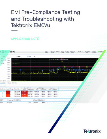
White PaperExtinction Ratio (ER) CalibratedPrecise Extinction Ratio measurement for optical 10 Gb/s signaling in Ethernetand SONET/SDHIntroductionOne of the most important measurements in optical NRZ signaling, Extinction Ratio (ER) was often consideredan unstable measurement. This has been corrected with the arrival of “ER Calibrated” measurement availableon Tektronix DSA8200 Series sampling oscilloscopes. This white paper explains some of the benefits of highlyaccurate ER measurements in both 10 GbE (Ethernet), with its relatively low ER requirement, and inSONET/SDH, and the methodology that supports consistent, accurate ER result.Background information on Extinction RatioCommonly called out in optical telecommunication standards, ER is a measure of modulation depth, and canbe used for example as a figure of merit of an optical modulator. The most common definition is the ratio ofpower between the logic One and logic Zero. See Figure 1.
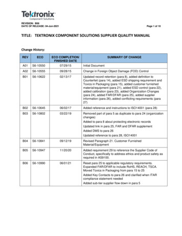
White PaperSimple RatioER E1 / E0PercentageER 100 (E0 / E1)orordBBER 10 (log (E1 / E0))“E1” Level is theMEAN of the verticalhistogram.Optical Power [W]Dark levelSingle bit UI duration“E0” Level is theMEAN of the verticalhistogram.Figure 1. Definition of Extinction Ratio measurement.There are two reasons why the E0, low-level power of the optical signal, introduces a difficulty in opticalmeasurements. First, the low level power measurement is greatly effected by DC offset of the measurementdevice (optical oscilloscope). This is effect is corrected by DC Compensation. Second, the AC response ofthe optical oscilloscope introduces ringing and dribble-up or dribble-down, also impacting the E0 value, andmaking the result of the fraction E1/E0 unstable. These AC effects were only recently handled by TektronixDSA8200 Series sampling oscilloscopes.Importance of accurate Extinction ratio in SONET/SDHIn systems where transmitter is described in terms of Average Optical Power (AOP) and ER, ER expresseshow much power is transmitted effectively – that is, how much is used by the modulation. This can then beexpressed in terms of loss, or in terms of BER Penalty. See Figure 2. This is the case in SONET/SDH, and inthat application the ER is mandated at relatively high level around 10 dB, and it is considered a non-trivial taskto comfortably achieve such level – especially before the advent of ER Calibrated feature. The value of havingan accurate, oscilloscope-to-oscilloscope guaranteed ER result is obvious in this application.
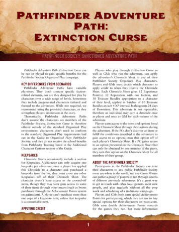
White PaperBER Penalty caused be ER109Penalty [dB]8765432100510152025ERFigure 2. BER Penalty due to ERImportance of accurate Extinction ratio in 10 Gb/s EthernetUnlike in SONET/SDH standards, the 10 Gb/s Ethernet standards (10 GbE), such as the original 802.3ae10GBASE-SR, 10GBASE-LR, etc.; the 802.3aq 10GBASE-LRM, and others, define power with OMA (OpticalModulation Amplitude) and ER is only set to an easy to reach 3 or 3.5 dB. This leads to commonmisconception that in Ethernet ER, and ER accuracy, is not of concern.While an ER of 3 dB is indeed much easier to achieve than the values used in SONET/SDH, the 10 GbEtechnology is different than that of SONET/SDH, and the directly modulated vertical cavity surface emissionlaser (VCSEL) used for 10 GbE exhibits growing amount of relaxation oscillation (ringing) as ER is adjustedupwards.For this reason it is desirable to keep ER low. Due to accuracy of measurement and end-of-life performance,the optimum value is a dB or two above the 3.0 or 3.5 dB prescribed by the standard. Most exacting systemvendors require tight specification for the ER value in Ethernet, which is one of the reasons why this is an issuefor the module manufacturer. See Figure 3.This ER result taken for one optical module, a module which should be adjusted to the specification of 5.5 dB. 6 dB ER. This module, measured with nine different optical oscilloscope modules with the traditional,uncalibrated ER measurement (shown in purple bar graph), evaluates as between 5.4 to 6.2 dB ER.In other words, due to the variability of the measurement equipment alone, one single module’s ER variesmore than the tolerance field for the whole product.
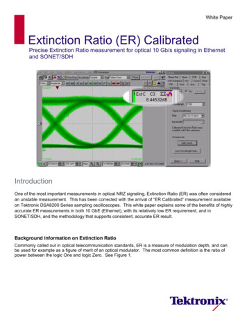
White PaperThe real result, guaranteed by Tektronix to a tight tolerance, is shown by the blue bar graphs on the right; herethe same nine optical oscilloscope sampling modules are used, but instead of the raw ER result their “ERCalibrated” result is plotted. So not only were the results in purple widely spread; even their mean is wrong.TOSA at 10.7Gb/s (low ER)7Raw ERCorrected ER6No. of units5432105.05.25.45.65.8 6.0 6.2ER (dB)6.46.66.8Figure 3. Single optical source measured with multiple measurement devicesEven in case when the targeted ER range is easier, e.g. 5 to 6 dB, it is clear that the manufacturing processwill be better controlled if the result is known with the accuracy shown by the blue bars on the right.Beyond manufacturing, stable and accurate ER result removes problems between the optical modulemanufacturer and their customer, since whatever results are shipped from manufacturing are then alsoconfirmed by the incoming inspection at the customer.Achievable AccuracyOptical oscilloscope module datasheets contain the specifications for guaranteed accuracy. See Figure 4.These plots show typical performance of ER Calibrated.
White PaperdB ER repeatability deviationdB ER repetability5254ER uncertainty range (dB)ER er ER (dB)16-5center ER (dB)Figure 4. ER Calibrated typical performanceConditions: Conditions: 50% 5 % mark density, PRBS-like distribution of run-lengths, 50 % 10 % eyecrossing levelLow ER Lasers (ER 6 dB): signal passes 802.3ae-like mask (scaled horizontally for bit-rate) with 0 margin;10 5 samples in mask.High ER Lasers (ER 6 dB): signal passes OC-192-like mask (scaled horizontally for bit-rate) with 10%margin; 10 5 samples in mask.Recommended ProcedureThe following sequence is recommended as best-practice to obtain the highest level in ER accuracy andrepeatability:Prior to any measurement the module and mainframe has to be fully warmed up ( 25 minutes) and full moduleCompensation has to be performed (see under Utilities- Compensation).Step 1. Under Setup- Horizontal set the bit rate to match the input data rate.Under Setup- Vertical- Optical select the applicable filter that matches the signal bit rate.Under Utilities- Autoset Properties select NRZ Eye.Step 2. Under Setup- Measurements- NRZ- Amplitude turn on“Extinction Ratio (dB) - Calibrated”. This measurement appears on the measurement sidebar as“ExtC”.Step 3. Apply the optical signal to the module input.Step 4. Perform AUTOSET. The eye diagram should now be centered on screen and cover about 80% ofthe vertical scale.Step 5. Disconnect or disable the optical input signal, perform a DARK LEVEL COMPENSATION (underSetup- Vertical- Optical) to zero out any finite offset in the sampling module.Step 6. Re-connect or enable the optical signal. Start acquisitions; after several waveforms have beenacquired (at least 1) perform CLEAR DATA; do not stop the acquisitions.Step 7. Continue acquiring at least 1M samples into the waveform database before recording the ERCalibrated result.
White PaperTechnical NotesTriggeringIt is critical that the triggering path and the trigger signal used during the Dark Level calibration remains thesame as during the measurement.So for example if Clock Recovery is used then the triggering should remain in Clock Recovery (without inputsignal the circuit will free-run, which is appropriate). If 80A06 Pattern sync is used then the 80A06 shouldremain programmed as is, and the clock signal to the 80A06 should be the same during the Dark Levelcompensation as it is during the normal operation.Speed of ExecutionIf speed of execution is very important and the repetitive execution of Dark Level Compensation presents ameasurement throughput problem then step 5. can be modified as follows: once an Autoset and DARKLEVEL COMPENSATION are done, save the value of Vertical Offset (Setup- Vertical- Offset) of themeasuring channel. The ER Calibrated measurement for next DUT can avoid Dark Level Compensation if thefollowing is fulfilled:The oscilloscope is running with the same triggering, horizontal, etc.;Also: the exactly same Vertical Offset is used; and the signal is close in size to a signal that went throughAutoset (signal fully fits onto the screen, has the proper time/div, and is larger than 3 divisions). In otherwords, the next DUT doesn’t need to be Autoset if its amplitude is similar to the 1st DUT. (Autoset wouldchange the Vertical Offset).Dark error, as measured by Mean (Pulse) measurement while no signal is connected, remains very small.Precise definition of ‘very small’ depends on ER Calibrated measurement accuracy required but e.g. for 80C11(as well as for the 80C09, 80C04, 80C02) this is below 1 µW while the signal is 500 µW or more; or a half ofthese amplitudes if 80C08 or 80C12 1 are used.Should any of the conditions above become impractical, the full procedure needs to be run. For example, if thenew DUT generates a signal so large that it will not fit onto the screen without a change to Vertical Offset, thenan Autoset followed by a new Dark Level Compensation needs to be done, as per the recommendedprocedure above.When measuring the residual offset Dark Level position do throw away the first waveform after Acquisition wasturned ON after the DARK LEVEL COMPENSATION. Leaving the acquisitions running and simply initiating aCLEAR DATA when the DARK LEVEL COMPENSATION is done is a good way to do that.1Some limitations and restrictions apply when using ER Calibrated on 80C12. Contact your Tektronix representative for moreinformation.
White PaperTroubleshootingIf the ER reports only “?”, several causes are possible. Troubleshoot in the order listed below.Step 1. Is the correct oscilloscope firmware installed?The oscilloscope FW version should be 5.0.0.5 or higher.(Pull down Utilities- System Properties for FW version).Step 2. Is the optical module optioned for ER Calibrated (option 01)?Pull down Setup- Vertical. Make sure the top-left readout “Waveform” shows your selectedchannel. See Figure 5. Compare the area circled in red.Figure 5. ER Calibrated Not installed (left) and Installed (right)The same operation can be achieved programmatically by executing commandERCAL ; example:ch3:ercal?will returnCH3:ERCAL 1if the option is enabled.Step 3. Is the ORR (Optical Reference Receiver) filter enabled?
White PaperFigure 6. ER Calibrated will report “?” if an ORR filter is not selectedStep 4. Was Compensation run? Was Dark Level run? Is the temperature stable?System compensation and Dark Level calibration must be performed; without them, the dark offsetmight make the result so wrong that the measurement finds a physically impossible (“dark light”)result – oscilloscope firmware then reports “?”. Following the steps above, you can trust the ERCalibrated result even if it’s higher than what you expect based on past results.Bibliography12132Jeffrey A. Jargon , Xiaoxia Wu , Paul D. Hale , Klaus M. Engenhardt , and Alan E. Willner , "Transmitter for Calibrating ExtinctionRatio Measurements of Optical Receivers," in Optical Fiber Communication Conference, OSA Technical Digest (CD) (OpticalSociety of America, 2009), paper JWA24.1National Institute of Standards and Technology, Boulder, CO, USA2University of Southern California, Los Angeles, CA, USA3Tektronix, Beaverton, OR, USACopyright 2010, Tektronix. All rights reserved. Tektronix products are covered by U.S. and foreign patents, issued and pending. Information in this publication supersedes that in all previously publishedmaterial. Specification and price change privileges reserved. TEKTRONIX and TEK are registered trademarks of Tektronix, Inc.All other trade names referenced are the service marks, trademarks or registeredtrademarks of their respective companies.03/2010Internal/WWW85W-25115-1
White Paper Extinction Ratio (ER) Calibrated . Precise Extinction Ratio measurement for optical 10 Gb/s signaling in Ethernet and SONET/SDH . Introduction. One of the most important measurements in optical NRZ signaling, Extinction Ratio (ER) was often considered an unstable measurement. This has been corrected with the arrival of "ER .