Transcription
SOLOMON SYSTECHSEMICONDUCTOR TECHNICAL DATASSD1331Product Preview96RGB x 64 Dot MatrixOLED/PLED Segment/Common Driver with ControllerThis document contains information on a product under development. Solomon Systech reserves the right to changeor discontinue this product without notice.http://www.solomon-systech.comSSD1331Rev 0.13 P 1/64Mar 2006Copyright 2006 Solomon Systech Limited
CONTENTSCONTENTS . 21GERENAL INFORMATION . 62FEATURES . 63ORDERING INFORMATION . 64BLOCK DIAGRAM . 75SSD1331Z GOLD BUMP DIE PAD ASSIGNMENT. 86PIN DESCRIPTION. 127FUNCTIONAL BLOCK DESCRIPTIONS . 157.1MCU INTERFACE SELECTION . 157.1.16800-series Parallel Interface . 157.1.28080-series Parallel Interface . 167.1.3Serial Interface. 177.2COMMAND DECODER .187.3OSCILLATOR CIRCUIT AND DISPLAY TIME GENERATOR . 187.3.1Oscillator . 187.3.2FR synchronization . 197.4RESET CIRCUIT . 197.5GRAPHIC DISPLAY DATA RAM (GDDRAM). 207.5.1GDDRAM structure . 207.5.2Data bus to RAM mapping under different input mode . 207.5.3RAM mapping and Different color depth mode. 217.6GRAY SCALE DECODER .217.7SEG / COM DRIVING BLOCK . 237.8COMMON AND SEGMENT DRIVERS . 247.9POWER ON AND OFF SEQUENCE . 278COMMAND TABLE . 288.19DATA READ / WRITE .34COMMAND DESCRIPTIONS . 359.1FUNDAMENTAL COMMAND .359.1.1Set Column Address (15h). 359.1.2Set Row Address (75h). 359.1.3Set Contrast for Color A, B, C (81h, 82h, 83h) .369.1.4Master Current Control (87h) . 369.1.5Set Second Pre-charge Speed for Color A, B, C (8Ah). 379.1.6Set Re-map & Data Format (A0h) . 379.1.7Set Display Start Line (A1h). 429.1.8Set Display Offset (A2h) . 429.1.9Set Display Mode (A4h A7h) . 459.1.10 Set Multiplex Ratio (A8h) . 459.1.11 Set Master Configuration (ADh). 459.1.12 Set Display On/Off (AEh / AFh) . 459.1.13 Power Save Mode (B0h). 459.1.14 Phase 1 and 2 Period Adjustment (B1h) . 459.1.15 Set Display Clock Divide Ratio/ Oscillator Frequency (B3h) . 469.1.16 Set Gray Scale Table (B8h) . 469.1.17 Enable Linear Gray Scale Table (B9h) . 479.1.18 Set Pre-charge voltage (BBh) . 479.1.19 Set VCOMH Voltage (BEh).479.1.20 NOP (BCh, BDh, E3h) . 479.1.21 Set Command Lock (FDh) . 479.2GRAPHIC ACCELERATION COMMAND SET DESCRIPTION. 489.2.1Draw Line (21h) . 489.2.2Draw Rectangle (22h) . 489.2.3Copy (23h) . 49Solomon SystechMar 2006P 2/64Rev 0.13SSD1331
9.2.49.2.59.2.69.2.79.2.89.2.9Dim Window (24h) . 49Clear Window (25h) . 50Fill Enable/Disable (26h). 50Continuous Horizontal & Vertical Scrolling Setup (27h) . 51Deactivate scrolling (2Eh) . 51Activate scrolling (2Fh) . 5110MAXIMUM RATINGS. 5211DC CHARACTERISTICS. 5312AC CHARACTERISTICS. 5413APPLICATION EXAMPLE . 5814PACKAGE OPTIONS . 5914.114.214.3SSD1331Z DIE TRAY INFORMATION . 59SSD1331U1R1 COF PACKAGE DIMENSIONS. 60SSD1331U1R1 COF PACKAGE PIN ASSIGNMENT. 62SSD1331Rev 0.13P 3/64Mar 2006Solomon Systech
TABLESTable 1 - Ordering Information . 6Table 2 - SSD1331Z Die Pad Coordinates. 9Table 3 - Bus Interface selection . 12Table 4 - MCU interface assignment under different bus interface mode. 15Table 5 - Control pins of 6800 interface . 15Table 6 - Control pins of 8080 interface . 16Table 7 - Control pins of 8080 interface (Alternative form). 17Table 8 - Control pins of Serial interface . 17Table 9 - Data bus usage under different bus width and color depth mode. 20Table 10 - Command Table. 28Table 11 - Address increment table (Automatic) . 34Table 12 - Illustration of different COM output settings . 39Table 13 - Example of Set Display Offset and Display Start Line with no Remap. 43Table 14 - Example of Set Display Offset and Display Start Line with Remap . 44Table 15 - Result of Change of Brightness by Dim Window Command. 49Table 16 - Maximum Ratings. 52Table 17 - DC Characteristics . 53Table 18 - AC Characteristics. 54Table 19 - 6800-Series MPU Parallel Interface Timing Characteristics . 55Table 20 - 8080-Series MPU Parallel Interface Timing Characteristics . 56Table 21 - Serial Interface Timing Characteristics . 57Table 22 - SSD1331U1R1 pin assignment . 63Solomon SystechMar 2006P 4/64Rev 0.13SSD1331
FIGURESFigure 1 - SSD1331 Block Diagram . 7Figure 2 - SSD1331Z Die Drawing . 8Figure 3 - SSD1331Z Alignment mark dimensions . 11Figure 4 - Display data read back procedure - insertion of dummy read . 16Figure 5 - Display data read back procedure - insertion of dummy read . 16Figure 6 - Write procedure in SPI mode . 17Figure 7 - Oscillator Circuit . 18Figure 8 - 65k Color Depth Graphic Display Data RAM Structure . 20Figure 9 - 256-color mode mapping . 21Figure 10 - Relation between GDRAM content and gray scale table entry for three colors in 65K color mode21Figure 11 - Illustration of relation between graphic display RAM value and gray scale control . 22Figure 12 - IREF Current Setting by Resistor Value . 23Figure 13 - ISEG current vs VCC setting at constant IREF, Contrast FFh . 23Figure 14 - Segment and Common Driver Block Diagram . 24Figure 15 - Segment and Common Driver Signal Waveform . 25Figure 16 - Gray Scale Control by PWM in Segment. 26Figure 17 : The Power ON sequence . 27Figure 18 : The Power OFF sequence . 27Figure 19 - Example of Column and Row Address Pointer Movement. 35Figure 20 - Segment Output Current for Different Contrast Control and Master Current Setting . 36Figure 21 - Effect of setting the second pre-charge under different speeds . 37Figure 22 - Address Pointer Movement of Horizontal Address Increment Mode . 37Figure 23 - Address Pointer Movement of Vertical Address Increment Mode . 37Figure 24 - Example of Column Address Mapping. 38Figure 25 - COM Pins Hardware Configuration (MUX ratio: 64) . 40Figure 26 - Typical Oscillator frequency adjustment by B3 command . 46Figure 27 - Example of gamma correction by gray scale table setting . 47Figure 28 – Typical Pre-charge voltage level setting by command BBh. 47Figure 29 - Example of Draw Line Command . 48Figure 30 - Example of Draw Rectangle Command. 48Figure 31 - Example of Copy Command . 49Figure 32 - Example of Copy Clear Move Command . 50Figure 33 - Examples of Continuous Horizontal and Vertical Scrolling command setup . 51Figure 34 - 6800-series parallel interface characteristics. 55Figure 35 - 8080-series parallel interface characteristics. 56Figure 36 - Serial interface characteristics . 57Figure 37 - Application Example for SSD1331U1R1. 58Figure 38 - Die Tray Information. 59Figure 39 - SSD1331U1R1 outline drawing . 60Figure 40 - SSD1331U1R1 pin assignment drawing. 62SSD1331Rev 0.13P 5/64Mar 2006Solomon Systech
1GERENAL INFORMATIONThe SSD1331 is a single chip CMOS OLED/PLED driver with 288 segments and 64 commons output,supporting up to 96RGB x 64 dot matrix display. This chip is designed for Common Cathode typeOLED/PLED panel.The SSD1331 had embedded Graphic Display Data RAM (GDDRAM). It supports with 8, 9, 16 bits 8080 /6800 parallel interface as well as serial peripheral interface. It has 256-step contrast and 65K color control.To facilitate communication between lower operating voltages MCU, it has separate power for I/O interfacelogic. SSD1331 is suitable for mobile phones, MP3, MP4 and other industrial devices.2FEATURES 3Resolution: 96RGB x 64 dot matrix panel65k color depth support by embedded 96x64x16 bit GDDRAM display bufferPower supply:for IC logico VDD 2.4V to 3.5Vo VCC 8.0V to 16.0Vfor Panel drivingo VDDIO 1.6V to VDDfor MCU interfaceSegment maximum source current: 200uACommon maximum sink current: 60mA256 step contrast control for the each color component plus 16 step master current controlPin selectable MCU interfaceo 8/9/16 bits 6800-series parallel Interfaceo 8/9/16 bits 8080-series Parallel Interfaceo Serial Peripheral InterfaceColor swapping function (RGB - BGR)Graphic Accelerating Command (GAC) set with Continuous Horizontal, Vertical and DiagonalScrollingProgrammable Frame RateWide range of operating temperature: -40 to 85 CORDERING INFORMATIONTable 1 - Ordering InformationOrdering Part NumberSEGCOMPackage FormReferenceSSD1331Z96x364COGPage 8, 59SSD1331U1R1Solomon Systech96x364COFPage 60Remark 35mm film, 5 sprocket hole8 bit or SPI interfaceOutput lead pitch: 0.06mm for SEG,0.09mm for COMMar 2006P 6/64Rev 0.13SSD1331
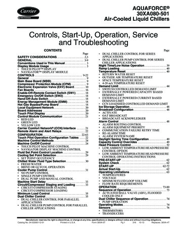
4BLOCK DIAGRAMSSD1331Rev 0.13P 7/64SEG/COM Driving blockVD D BVS S BGDRFBVB R E FMar SC1SB1SA1SC0SB0SA0COM0COM2COM4.COM58COM60COM62IR E FVC O M HDisplay TimingGeneratorFRCLGP1CLSGP0OscillatorCommand DecoderVDDIOVSSVLSSAVDDCommon Drivers(odd)VCCVDDSegment DriversD[15:0]COM63COM61COM59.COM5COM3COM1Common Drivers(Even)BS[3:0]GDDRAMMCU InterfaceRES#CS#D/C#E(RD#)R/W #(WR#)Gray Scale DecoderFigure 1 - SSD1331 Block DiagramSolomon Systech
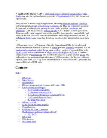
5SSD1331Z GOLD BUMP DIE PAD ASSIGNMENTFigure 2 - SSD1331Z Die DrawingPad 1Die sizeDie heightMin I/O pad pitchMin SEG pad pitchMin COM pad pitchBump height13.1mm x 1.58mm457um76.2 um40.2 um41.8 umNominal 15umBump sizePad 1-163Pad164-195, 486-517Pad 196-48550um x 72um72um x 28um28um x 72umAlignment mark(5446.0, -402.0)(-5446.0, -402.0) shape shapeSSD1331ZSolomon Systech75um x 75um75um x 75umYXPad 1,2,3, - 163Gold Bumps face upMar 2006P 8/64Rev 0.13SSD1331
Table 2 - SSD1331Z Die Pad CoordinatesP a d no 80P ad N SSVLSSVLSSVLSSVLSSVLSSVSSVSSVSSB DVDDFBVB REFVSSGP 0GP 1VDDIOVCIRVCIRVCIRVCIRVCIRVDDVDDVDDVDDA VDDA VDDVDDIOVDDIOVDDIOVDDIOVDDIOVDDIOB S0VSSB S1VDDIOSSD1331X - A 4Rev 0.13Y - A 2.5-712.5-712.5-712.5-712.5-712.5P 9/64P a d no 3154155156157158159160Mar 2006P ad N ameB S2VSSB R8TR7TR6VSSTR5TR4TR3TR2TR1TR0VSSVCOM HVCOM HVCOM CX - A 1.26014.66090.8Y - A 2.5-712.5-712.5-712.5-712.5-712.5P a d no 27228229230231232233234235236237238239240P ad N ameNCNCNCCOM 31COM 30COM 29COM 28COM 27COM 26COM 25COM 24COM 23COM 22COM 21COM 20COM 19COM 18COM 17COM 16COM 15COM 14COM 13COM 12COM 11COM 10COM 9COM 8COM 7COM 6COM 5COM 4COM 3COM 2COM 1COM 0VLSSSA 0SB 0SC0SA 1SB 1SC1SA 2SB 2SC2SA 3SB 3SC3SA 4SB 4SC4SA 5SB 5SC5SA 6SB 6SC6SA 7SB 7SC7SA 8SB 8SC8SA 9SB 9SC9SA 10SB 10SC10SA 11SB 11SC11SA 12SB 12SC12SA 13SB 13SC13SA 14SB 14X - A 0.54260.34220.14179.94139.74099.5Y - A 3.6643.6643.6643.6Solomon Systech
P a d no 07308309310311312313314315316317318319320P ad N ameSC14SA 15SB 15SC15SA 16SB 16SC16SA 17SB 17SC17SA 18SB 18SC18SA 19SB 19SC19SA 20SB 20SC20SA 21SB 21SC21SA 22SB 22SC22SA 23SB 23SC23SA 24SB 24SC24SA 25SB 25SC25SA 26SB 26SC26SA 27SB 27SC27SA 28SB 28SC28SA 29SB 29SC29SA 30SB 30SC30SA 31SB 31SC31SA 32SB 32SC32SA 33SB 33SC33SA 34SB 34SC34SA 35SB 35SC35SA 36SB 36SC36SA 37SB 37SC37SA 38SB 38SC38SA 39SB 39SC39SA 40SB 40SC40SA 41X - A 4.51044.31004.1963.9923.7883.5Solomon SystechY - A 3.6P a d no 87388389390391392393394395396397398399400P ad N ameSB 41SC41SA 42SB 42SC42SA 43SB 43SC43SA 44SB 44SC44SA 45SB 45SC45SA 46SB 46SC46SA 47SB 47SC47SA 48SB 48SC48SA 49SB 49SC49SA 50SB 50SC50SA 51SB 51SC51SA 52SB 52SC52SA 53SB 53SC53SA 54SB 54SC54SA 55SB 55SC55SA 56SB 56SC56SA 57SB 57SC57SA 58SB 58SC58SA 59SB 59SC59SA 60SB 60SC60SA 61SB 61SC61SA 62SB 62SC62SA 63SB 63SC63SA 64SB 64SC64SA 65SB 65SC65SA 66SB 66SC66SA 67SB 67SC67X - A 2211.9-2252.1-2292.3-2332.5-2372.7-2412.9-2453.1Y - A 3.6P a d no 67468469470471472473474475476477478479480Mar 2006 P 10/64P ad N ameSA 68SB 68SC68SA 69SB 69SC69SA 70SB 70SC70SA 71SB 71SC71SA 72SB 72SC72SA 73SB 73SC73SA 74SB 74SC74SA 75SB 75SC75SA 76SB 76SC76SA 77SB 77SC77SA 78SB 78SC78SA 79SB 79SC79SA 80SB 80SC80SA 81SB 81SC81SA 82SB 82SC82SA 83SB 83SC83SA 84SB 84SC84SA 85SB 85SC85SA 86SB 86SC86SA 87SB 87SC87SA 88SB 88SC88SA 89SB 89SC89SA 90SB 90SC90SA 91SB 91SC91SA 92SB 92SC92SA 93SB 93SC93SA 94SB 94Rev 0.13X - A 900.3-3940.5-
SSD1331 is suitable for mobile phones, MP3, MP4 and other industrial devices. 2 FEATURES Resolution: 96RGB x 64 dot matrix panel 65k color depth support by embedded 96x64x16 bit GDDRAM display buffer Power supply: . 2 NC -6243.2 -712.5 82 VSS 0.0 -712.5 162 NC 6243.2 -712.5