Transcription
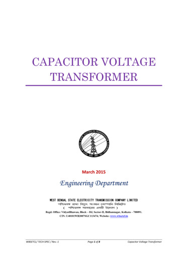
Impact of the transformer’s grounding methodon its transient performance under lightingimpulseDr. Waldemar ZiomekSenior Expert – Power Transformers and HV InsulationPTI Manitoba Inc., Winnipeg, CanadaPTCAPTI Manitoba Inc.November2015April 2017IEEE CONFIDENTIALTransformers Committee1 1
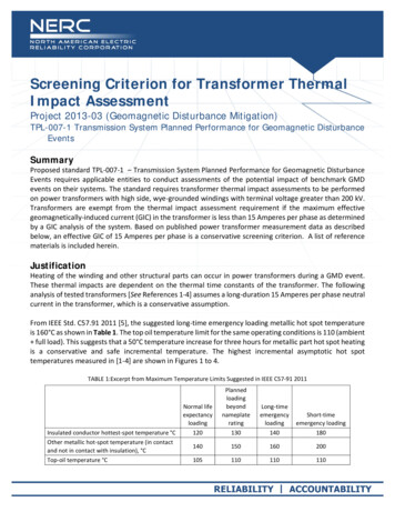
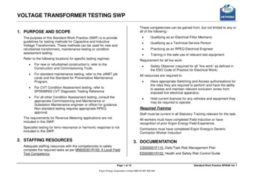
IntroductionThe industry standards for grounding methods (e.g. IEEE Std 142 ) describe the system configurationsand impact of grounding method on performance of the system, but do not estimate the impact of thegrounding method on the overvoltages inside the neutral-grounded transformer.This study will analyze the influence of specific grounding method, i.e. directly, through reactance orresistance, on the transients developing in a transformer under lightning impulse.The calculation of internal overvoltages inside the transformer can be performed using differentmethods, however the most popular is a lumped parameter method in which the physical winding isrepresented by a system of RLC components. An equivalent circuit of the transformer is created bysubdividing the winding into a cascade of equivalent RLC circuits. The RLC circuit parameters arecalculated considering the ohmic value of resistance between the terminals of each winding, the valueof self-inductance of each coil, L, the values of mutual inductances between the coils, M, thecapacitance values found along each coil (series capacitances - Cs) and the values of capacitancesbetween adjacent coils and between coils and grounded structural parts of the transformer(capacitances to ground - Cg). An example of such winding model is illustrated in Figure 1, excludingmutual inductances. In this example the winding is divided into n branches or inductive elements,represented in the model by ‘local’ RiLiCi components. By increasing the number of circuits by finersubdivisions, the accuracy can be extended to higher frequency.PTCAPTI Manitoba Inc.November2015April 2017IEEE CONFIDENTIALTransformers Committee2 2
IntroductionFigure 1 Transient response of a transformer winding to standard lightning impulse with the neutraldirectly grounded; a) representation of a transformer winding for transient studies as a ladder of MLRCelements (mutual inductances, Mij, not shown), b) voltage distribution along the winding vs time for ahelical windingPTCAPTI Manitoba Inc.November2015April 2017IEEE CONFIDENTIALTransformers Committee3 3
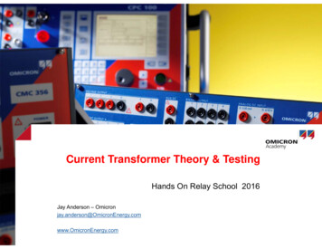
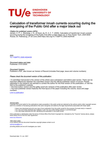
IntroductionFigure 2 Representation of one phase of a transformer with windings coupled through capacitances toeach other and to groundPTCAPTI Manitoba Inc.November2015April 2017IEEE CONFIDENTIALTransformers Committee4 4
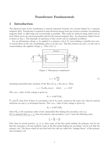
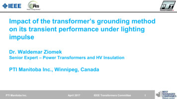
IntroductionHV SYSTEMLV SYSTEMBuried TVFigure 3 Example of a three-phase transformer with three circuits; TV is buried, delta-connected withone corner directly grounded; LV and HV windings are wye-connected with directly grounded neutralsPTCAPTI Manitoba Inc.November2015April 2017IEEE CONFIDENTIALTransformers Committee5 5
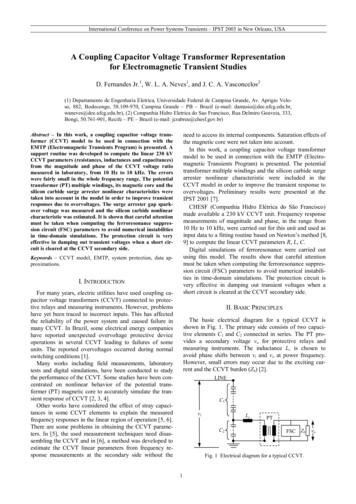
IntroductionShort examination of the model shown in Figure 3 would lead to a conclusion that prediction ofsuch a transformer model’s behavior under a lightning impulse excitation without performing allnecessary transient calculations is not possible, especially if one would need to take intoaccount interaction between windings of a phase subjected to the impulse (transferred surge),transients flowing to connected phases, action of non-linear arrestors, if any, impact of thegrounding method, etc. Only through generation of a precise model the proper transientcharacteristic of a transformer can be obtained.Moreover, if a transformer is connected to a specific power system, such interaction between atransformer and system needs to be taken into account, especially the presence and transientcharacteristics of circuit-breakers, transmission line(s), cables, etc.In all cases described above the winding neutral was grounded directly, hence the voltage inneutral would be zero. Various types of system grounding (ungrounded, directly grounded,grounded through resistance, reactance or ground-fault neutralizer) with a systemcharacteristics are described in IEEE standard. Three grounding types relevant to this study –direct grounding, grounding through resistance or reactance - are presented in Figure 4.PTCAPTI Manitoba Inc.November2015April 2017IEEE CONFIDENTIALTransformers Committee6 6
IntroductionFigure 4 Selected cases for transformer grounding and corresponding zero-sequencecomponents of neutral circuit; XG0 – zero sequence impedance of transformer or generator, RN –resistance of a grounding resistor, XN – reactance of a grounding reactor (from IEEE Std 142)PTCAPTI Manitoba Inc.November2015April 2017IEEE CONFIDENTIALTransformers Committee7 7
Transient study ona windfarm collector step-up transformerPower rating:Cooling type:Winding temperature rise:Liquid top temperaturerise:HV rated voltageLV rated voltageTVInsulating liquidLTC in HV neutral for HVvariationPTCAPTI Manitoba Inc.Rating200 MVAONAN/ONAF/ONAF65oC average/80oC hot spot65oCTerminalH1, H2, H3H0X1, X2, X3X0Winding BIL [kV]1050110200200345 000 GrdY/ 199 200 V34 500 Y/ 19 200 VburiedMineral oil, Type IIMR VM-III-500Y-72.5/CNovember2015April 2017IEEE CONFIDENTIALTransformers Committee8 8
Transient study ona windfarm collector step-up transformerThe objective of this study is to evaluate the transient performance of a transformer under LIexcitation (LI applied in turn to HV and LV terminals) for three different methods of theneutral grounding: directly, by resistance, or by reactance.The study was performed on a three-phase model of a transformer, with a TV windinggrounded directly in one corner and the HV neutral directly grounded, under lighting impulsefor both full wave (FW) at 200kV, 1.2/50 ms and chopped wave (CW) at 220kV and 3.5/50ms.As the performance under LV CW impulse at 220 kV is decisive, only these results arepresented here.PTCAPTI Manitoba Inc.November2015April 2017IEEE CONFIDENTIALTransformers Committee9 9
Directly grounded LV neutralPTCAPTI Manitoba Inc.November2015April 2017IEEE CONFIDENTIALTransformers Committee1010
Resistance grounded LV neutralPTCAPTI Manitoba Inc.November2015April 2017IEEE CONFIDENTIALTransformers Committee11 11
Reactance grounded LV neutralPTCAPTI Manitoba Inc.November2015April 2017IEEE CONFIDENTIALTransformers Committee1212
Reactance grounded LV neutral –the voltage across NGRThe voltage across the neutral grounding reactance vs time during 220 kV LI (CW)applied to the LV line terminal – maximum voltage across the reactor is 138kVPTCAPTI Manitoba Inc.November2015April 2017IEEE CONFIDENTIALTransformers Committee1313
Comparison of CW impulse resultswith different grounding methodsLV neutral’s groundingmethod:Directly groundedResistance groundedReactance groundedLV voltage to gnd[kV]TV voltage tognd [kV]TV to LVvoltage [kV]TV voltage 260/-280From the above shown results one may see that the magnitudes of overvoltages developinginside a transformer with the neutral grounded by reactance are significantly higher than thoseachieved with the neutral directly grounded or resistance-grounded. While LV voltage to grounddoes not change significantly with grounding method, the voltage from TV to ground and to LVis some 35-45% higher when the neutral is reactance-grounded, with worst case for the voltageLV-TV increasing twice for this type of grounding.These results were re-checked by performing RSG tests, which confirmed the higher transientvoltages at reactance grounding, but it was noticed that due to damping and air background (vsoil) the differences between resistance/direct vs reactance grounding were around 25-35%.PTCAPTI Manitoba Inc.November2015April 2017IEEE CONFIDENTIALTransformers Committee1414
Conclusions from a study The industry standards for grounding methods (e.g. IEEE Std 142) describe the systemconfigurations and impact of grounding method on performance of the system, but donot estimate the impact of the grounding method on the overvoltages inside theneutral-grounded transformer. Grounding a transformer directly or with a resistor results in lower internalovervoltages, than those appearing when a neutral grounding reactor is used: e.g.based of this study one may state that while the LV voltage to ground does not changesignificantly with grounding method, the voltage from a TV winding to ground and to theLV winding is some 35-45% higher when the neutral is reactance-grounded, with worstcase for the LV-TV voltage increasing twice for this type of grounding.PTCAPTI Manitoba Inc.November2015April 2017IEEE CONFIDENTIALTransformers Committee1515
Conclusions from a study As a prediction of the transformer and system performance under transients is strictlydependent of their characteristics, specific to given design, location, systemconfiguration, and type of the neutral grounding device, such a study should beperformed in the design stage for a specific transformer. This case demonstrated that the transients developing inside the transformer under LIwith the neutral grounding reactor are excessive, would lead to a failure of thetransformer. On the other hand, the analysis of the voltage appearing across theneutral grounding reactor showed that this voltage is high, but it could be controlled byhigher BIL of the transformer neutral or application of an arrester. Therefore a warningneeds to be formed: when using the neutral grounding reactor, the transientvoltages need to be thoroughly analyzed not only across the grounding device,but more importantly – inside the transformer to whose neutral this device isconnected. This is typically analyzed when the NGR is defined in the specification, butmay be a problem when the user of a transformer decides to change the groundingmethod later, e.g. after a few years in operation.PTCAPTI Manitoba Inc.November2015April 2017IEEE CONFIDENTIALTransformers Committee1616
Proposal for IEEE Std C57.142The transformer neutral grounding methodTypically, the analysis of the transformer response to a transient excitation is performed with the excitedwinding’s neutral grounded directly; hence the voltage in the neutral would be equal to zero, if one wouldignore the ground impedance. This is a very typical situation for the large power, high voltage transformers,but in many situations the grounding method may be different and would have impact on the development ofthe oscillatory voltages inside the transformer under transient conditions. Various types of system grounding(i.e. ungrounded, directly grounded, grounded through resistance, reactance or ground-fault neutralizer) with asystem characteristics are described in IEEE Standard 142.PTCAPTI Manitoba Inc.November2015April 2017IEEE CONFIDENTIALTransformers Committee1717
Proposal for IEEE Std C57.142The impact of the neutral grounding method on the transient response of a transformer cannot be predicted without performingthe transient calculations, nevertheless one may observe the following characteristics of some of these methods: The direct grounding will ensure that the voltage in the neutral is zero, or near zero – for both steady state and transients(the voltage rise of neutral during the system faults is not discussed here),The resistive grounding will have a damping effect on the transients – both inside and outside a transformer, asresistance will dissipate the energy of transient current; it is stated in [1] that “a system properly grounded by resistance isnot subject to destructive transient overvoltages”;The grounding by reactance will sustain the transient state and lead to overvoltages as reactance will store and releasethe electric energy, We:1𝑊𝑒 2 𝐿𝑖 2In other words, one may expect that the presence of the reactance in the neutral will promote and uphold the transientovervoltages inside and outside the transformer; as the energy stored in the reactor flows through the system including atransformer – one may expect its possible adverse impact of the transient voltages inside the transformer. The standard [1]addresses the presence of reactance in the neutral only for the system faults and states as follows: “in reactance-groundedsystem, the available ground-fault current should be at least 25% and preferably 60% of the three-phase fault current toprevent serious overvoltages (X0 10X1)”.PTCAPTI Manitoba Inc.November2015April 2017IEEE CONFIDENTIALTransformers Committee1818
Proposal for IEEE Std C57.142As the transformer and system performance under transients is strictly dependent of their characteristics,specific to given design, location, system configuration, etc., there is no universal description covering allpossible cases. Some specific theoretical and experimental work related to the methods of transformergrounding can be found in the references [2-4], but a detailed analysis of a specific case is always required tofully understand the response of a given transformer to transients.Under typical circumstance the neutral grounding method is communicated to the transformer manufacturerand its impact on the transient voltages can be taken into account during design and can be mitigated bydeveloping the enhanced insulation system or application of the internal, or external non-linear resistors.The situation becomes more complicated if the transformer grounding method is changed later, e.g. by a newowner of the substation, and the transformer manufacturer is not consulted for possible impact of a newgrounding method on the oscillatory overvoltages developing inside the transformer under transientexcitation. This may result in the excessive internal voltages breaking down the transformer insulation systemand leading to a transformer failure.PTCAPTI Manitoba Inc.November2015April 2017IEEE CONFIDENTIALTransformers Committee1919
References[1] IEEE Std 142 – Recommended Practice for Gr
The industry standards for grounding methods (e.g. IEEE Std142) describe the system configurations and impact of grounding method on performance of the system, but do not estimate the impact of the grounding method on the overvoltages inside the neutral-grounded transformer.