Transcription
Gearbox Typical FailureModes, Detection andMitigation MethodsShawn ShengNational Renewable Energy Laboratory/National WindTechnology CenterAWEA Operations & Maintenance and Safety SeminarJanuary 15–16, 2014NREL/PR-5000-60982NREL is a national laboratory of the U.S. Department of Energy, Office of Energy Efficiency and Renewable Energy, operated by the Alliance for Sustainable Energy, LLC.
Outline Background Gearbox Typical Failure Modes BearingsGearsLubricant Detection Techniques Real-timePeriodic Mitigation Strategies BearingsGearsLubricant2
Background
Gearbox Reliability Challenges Gearboxes do not alwaysachieve their 20-year designlife Premature gearbox failures:Are widespread Affect most original equipmentmanufacturers (Most) are not caused bymanufacturing practices, exceptgrind temper and nonmetallicinclusions Gearbox largest contributorto turbine downtime andcostliest to repair** Sheng, S. (2013). “Report on Wind Turbine Subsystem Reliability – A Survey of Various Databases.” June 2013. NREL/PR-5000-59111.4
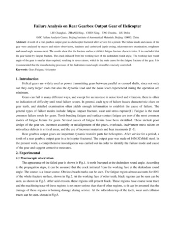
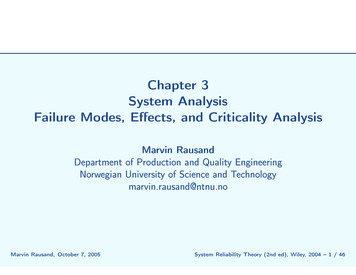
Gearbox Damage Gearboxes can fail in drastically different waysData: 257 gearbox damaged recordsBearings: 70%; gears: 26%; and others: 4%Observations: Both bearing and gear failures are concentrated in the parallel section Top failure mode is high-speed shaft (HSS) or intermediate-speed shaft (IMS)bearing axial N/A34HSSN/A123Total257180Others9476895
Typical Failure Modes
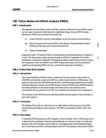
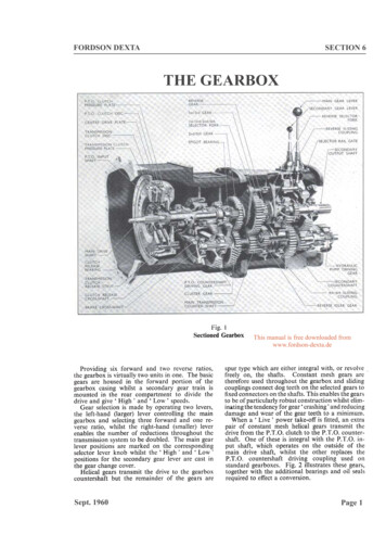
A Representative diate-SpeedStage7
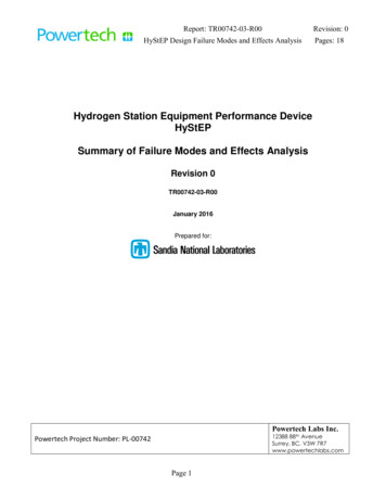
Typical Failure Modes: BearingsMacropitting Axial Cracks Recent failure mode of significant proportions Most appear initiated with irregular whiteetching areas Manifests as axial cracks within the roller path Progresses to macropitting, split inner ring, orbothFretting corrosionScuffingDenting/Point-surfaceorigin (PSO) macropittingFalse brinellingPhoto Credits: Bob Errichello, GEARTECH, Johan Luyckx, Hansen Transmissions, Andy Milburn, Milburn Engineering, and Ryan Evans,Timken8
Typical Failure Modes: GearsSubsurface initiated bending fatigue(due to nonmetallic inclusion,intermediate-speed stage pinion)Fretting corrosion (sun pinion)Scuffing (high-speed stage pinion)Micropitting/macropittingPhoto Credit: Bob Errichello, GEARTECH9
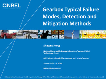
Typical Failure Modes: LubricantR&O Mineral Oil100.090.080.070.060.0% Electrooxidizable Additives50.0Viscosity @ 40 C40.030.0New Oil Vis. 46.7020.048.27 Viscosity @ 40 C cStPercent of New Oil Additive% Additives vs. Viscosity @ 40 C cSt D-445108Days Aged in Turbine Oil Stability Test D-94303672Plot Credit: Bill Herguth, Herguth Laboratories10
Typical Failure Modes: Lubricant (Cont.) Contaminations include: Wear debris Dust Foam Breathing ofhousing Air trapped in oil Not enoughsettling timePhoto Credits: Bill Herguth, Herguth Laboratories, and Art Miller, EDFR11
Detection Techniques
Real-Time Continuous Critical SCADA data trending: Temperature of high-speed stagebearing, targeting surface damagemodes: pitting, scuffing, and soon Vibration analysis:Dedicated condition monitoringsystem with sensor bandwidth upto more than 10 kHz Effective for high-speed shaft,intermediate-speed shaft bearing,and gear surface damage modes:axial cracks, macropitting,scuffing, and so on Earlier detection than oil debrisanalysis, but challenging to detectdamage to planetary stagebearings and gears 13
Periodic Oil sample analysisSix months or annual oil samples sent to dedicated laboratories for typical physicaland chemical property analysis: viscosity, additives depletion, and so on Debris element analysis may pinpoint failed components: bearings, gears, and so on Good for oil condition, not very good for conditions of bearings and gears Filter element analysisOld filter cartridge can be sent to dedicated laboratories for analysis when it isreplaced with a new one Reveals what is typically missed in conventional oil sample analysis Identifies composition of wear debris and pinpoints damaged components: bearings,gears, and so on Reference LimitsAnalysis Results14
Periodic (Cont.) Portable vibration sweepSensors are similar to what are used by permanently installedvibration analysis systems Typically conducted during end-of-warranty (EOW) inspectionstargeting the same damage modes as permanently installed vibrationsystems Difficult to track down failure history Borescope inspectionDedicated scope to inspect all accessible stages of gearboxesNormally triggered by abnormal symptoms on the gearboxesdetected by other methods and used to confirm the damage,evaluate its severity level, and inform maintenance planning: damagemodes observable on component surfaces, pitting, scuffing, andproblems with the lubricant such as foaming Another scenario for conducting borescope inspections is during anEOW sweep Depending on gearbox configuration, the inspection may not bethorough because of the difficulty in accessing and photographingcertain components 15
Mitigation Strategies
Bearing Axial Cracks Carburized instead of through hardened bearings1 For carburized bearings, the level of retainedaustenite is recommended to be at least around20%1 Assembly temperature of bearing inner ringsaround 120 degrees Celsius2 Reduce transient event frequencies and theirmagnitudes Keep lubricant cool, clean, and dry1. Errichello, R.; Budny, R.; Eckert, R. (2013) “Investigations of Bearings Failures Associated with White Etching Areas (WEAs) in WindTurbine Gearboxes.” Tribology Transactions, Vol. 56, No. 6, pp. 1069-1076, DOI:10.1080/10402004.2013.8235312. Luyckx, J. (2011) “Hammering Wear Impact Fatigue Hypothesis WEC/irWEA Failure Mode on Roller Bearings.” Wind TurbineTribology Seminar, Broomfield, CO.17
Bearing/Gear Micropitting Grind/hone/polish gear teethSuperfinish, coat, or smooth bearing rings or elementsAvoid shot-peened flanksMake hardest gear/bearing element as smooth aspossibleMake pinion 2 HRC points harder than gearUse oil with high micropitting resistanceKeep lubricant cool, clean, and dryUse high-viscosity lubricantOperate at high speedsCoat teeth with phosphate, Cu, or AgRun-in with special lubricant [w/o ZDDP (Zinc DialkylDithio Phosphate)] at controlled loadsErrichello, R. (2011) “Wind Turbine Gearbox Failures.” Wind Turbine Tribology Seminar, Broomfield, CO.18
Gear Scuffing Optimize gear geometry/accuracy Use nitrided steel Grind/hone/superfinish gear teeth Coat gear teeth with phosphate, Cu, Ag Use high-viscosity antiscuff lubricant Cool gear teeth with lubricant Run-in new gear-sets at reduced loadsErrichello, R. (2011) “Wind Turbine Gearbox Failures.” Wind Turbine Tribology Seminar, Broomfield, CO.19
Lubricant Contamination Pre-filter oilRun-in oil flushingMain loop filtrationOffline loop filtrationBreatherHeat exchangerPeriodic seal examinationsPhoto Credit: Don Roberts, DA Roberts LLC.20
Summary
Summary Wind turbine gearboxes can fail in dramatically different ways. Improvements in reliability and availability have to take aholistic approach involving design, manufacturing, testing,packaging/shipping/handling, installation, operation, andmaintenance. It also involves almost all stakeholders, gearboxOEMs, turbine OEMs, owners/operators, research institutes,governmental agencies, and so on. Each detection technique has its own advantages andlimitations. The same is true for oil sample/filter elementanalysis, and end users need to come up with a solution that isthe most economical and effective for their assets. Note thatone solution for one plant may not apply to a different site. Tracking and knowing your fleet condition through variousinstrumentation and data mining are critical.22
Gearbox Reliability Improved Wind Stats data from Germany: about 5,000 turbines, majorities megawattscale Both 2007 and 2012 data indicate the gearbox as the highest downtime driver,but this was reduced by 67.7% in 2012 with respect to 2007 Most subsystems show improved reliability and total downtime caused by allsubsystems per turbine; in 2012 shows 47.1% reduction with respect to 200723
Thank You!Valuable reviews and comments from Bob Errichello are greatly appreciated!NREL’s contributions tothis presentation werefunded by the Wind andWater Power Program,Office of Energy Efficiencyand Renewable Energy,U.S. Department ofEnergy under contract No.DE-AC02-05CH11231.The authors are solelyresponsible for anyomissions or errorscontained herein.Photo from HC Sorensen, Middelgrunden Wind Turbine Cooperative, NREL 17855shuangwen.sheng@nrel.gov303-384-710624
Premature gearbox failures: Are widespread Affect most original equipment manufacturers (Most) are not caused by manufacturing practices, except grind temper and nonmetallic inclusions Gearbox largest contributor to turbine downtime and costliest to repair* * Sheng, S. (2013). “Report on Wind Turbine Subsystem Reliability – A Survey of Various Databases.” June 2013. NREL/PR -5000 59111.