Transcription
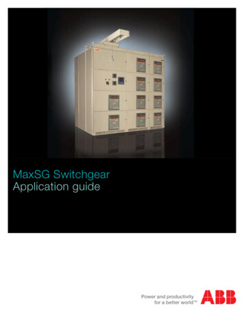
MaxSG SwitchgearApplication guide
MaxSG Application GuideTable of contentsGeneral.2Product DescriptionSystem Overview and Standards.3.Ratings.4.Ambient Conditions.4.Overall System Derating.5.Breaker Derating.5.Breaker Loss.6.Breaker Temperature Derating.6Technical DataStructure.7.Standard Finish and Frame.8.Available Dimensions. 8-9.Shipping Design.9.Barriers and Covers.11Nameplates.11.Enclosure.12.Bus Bar System. 13-15.Wiring. 16-17Instrumentation/MeteringVoltage Transformer.18.Control Power Transformer.18.Current Transformers. 22-23Zero Sequence Current Transformers. 19-20.Metering.21.Breaker Control Switch and Selector Switches.22ABB FT-1 Test Switch.22.Space Heaters.23Emax Power BreakersInterrupting Ratings. 24-25.Rating Plugs.26Breaker Details.27.Cradle Details.28Trip Units PR121/P. 29-35Trip Units PR122/P. 36-48Trip Units PR123/P. 49-58.Accessories for Trip Units. 59-63.Breaker Electrical Accessories. 64-70Breaker Mechanical Accessories. 71-72Features and Options. 73-82Arc Flash Safety Options. 83-86Communications. 87-92Applications. 93-98Layouts. 99-110Attachments. 111-131Low Voltage Products & SystemsABB Inc. 888-385-1221 www.abb.us/lowvoltage11SXU900121M0201
GeneralThe MaxSG has been utilized in the following markets: Oil and gasUtility and co-generationPharmaceuticalFood and beverageHealth careCritical power and dataMarine Mining & materialsSteel millWaste waterPower generationAerospaceSemiconductorcenters manufacturingSystem OverviewThe MaxSG low voltage switchgear is designed, constructed,and tested to provide superior power distribution, protection, and power monitoring and control. MaxSG is designedto maximize the functionality of the World Class Emax powercircuit breakers. It follows the vision of ABB products in providing customers with advanced solutions to meet the needsassociated with the mechanical, electrical and thermal stressof today’s manufacturing environment.The MaxSG Metal-Enclosed Low Voltage Switchgear offersmany advantages that include: Modular frame design arrangements for flexibilityNo front door breaker ventilationOptional barriers for increased personnel protectionMaintenance Switch OptionInsulated bus through 4000AStandard connections to a full range of ABB productsModbus Communication REA Relay Arc Flash System21SXU900121M0201Low Voltage Products & SystemsABB Inc. 888-385-1221 www.abb.us/lowvoltage
Product DescriptionSystem OverviewThe basic design: Standard UL1558 and ANSI C37.20.1Modular frame arrangementsEfficient and flexible designsOperational reliabilityEnclosure Types: NEMA-1 (with gasketed doors) and NEMA3R Walk InMaxSG is available with the following nominal ratings: 600Vac max 4000A max 50/60 Hz 2200Vac RMS Dielectric 65kA and 100kA Symmetrical Short Circuit withstand ratingStandardsThe MaxSG with Emax power breakers is designed, tested, and constructed in accordance with the followingindustry standards: UL 1558 — Metal-Enclosed Low Voltage Power Circuit Breaker SwitchgearANSI C37.20.1 — Metal-Enclosed Low Voltage Power Circuit Breaker SwitchgearANSI C37.50 — Test Procedure for Low Voltage AC Power Circuit Breakers Used in EnclosuresANSI C37.51 — Conformance Testing of Metal-Enclosed Low Voltage AC Power Circuit Breaker Switchgear Assemblies CSA C22.2 No. 31– Switchgear Assemblies Seismic Qualification to IBC-2006 and CBC-2007, AC156, “Shake-Table Testing for Nonstructural Components and Systems,” and ASCE/SEI 7-05, “Minimum Design Loads for Buildings and Other Structures”.The Emax power breakers are designed, tested, and constructed in accordance with the following standards. ANSI C37.13 — Low Voltage AC Power Circuit Breakers Used in Enclosures ANSI C37.16 — Preferred Ratings, Related Requirements, and Application for Low Voltage Power CircuitBreakers and AC Power Circuit Protectors ANSI C37.17 — Trip Devices for AC and General Purpose DC Low-Voltage Power Circuit Breakers UL1066 – Low Voltage AC and DC Power Circuit Breakers Used in EnclosuresLow Voltage Products & SystemsABB Inc. 888-385-1221 www.abb.us/lowvoltage31SXU900121M0201
Product DescriptionRatingsDescriptionValueRated continuous currentRated tested maximum voltageRated voltage240Vac, 480Vac, 600VacPhasesNeutralFrequencyShort circuit current withstand at 600VacMax peak short circuit current149.5 kA, 230 kA2000, 3200, 4000A3 phase 3 wire, 3 phase 4 wire254Vac, 508Vac, 635Vac50/60 Hz3 phase 3 wire, 3 phase 4 wire100% rated50/60 Hz65 kA, 100 kAAmbient ConditionsRequirementsTemperature range during operationUnit CValue-25 to 40Temperature range for transport and storage C-40 to 70Maximum bus temperature C65 over 40For ambient temperature of 50 C ABB self certification letter to be provided.Place of operation41SXU900121M0201Indoor and OutdoorLow Voltage Products & SystemsABB Inc. 888-385-1221 www.abb.us/lowvoltage
Product DescriptionOverall System DeratingANSI Switchgear Altitude Correction FactorsAltitude (m)VoltageCurrent2000m and below1.001.002600m0.950.993900m0.800.96Notes: Intermediate values may be obtained by interpolation. For devices used in switchgear assemblies, standards covering the specific devices should be used todetermine the specific altitude correction factors. 1000m is approximately 3300 ft. All values are under review by an IEEE Switchgear Committee Working Group, PC37.100.1 on CommonRequirements for Power Switchgear and are provided here for reference until revised values are available.Breaker DeratingThe Emax power breakers do not undergo any changes in their rated performance up to an altitude of 6600 ft(2000m).As the altitude increases the atmospheric properties alter in terms of composition, dielectric capacity, coolingpower and pressure. Therefore the breaker undergoes the following derating:Altitude(ft)(m) 6600200099003000132004000165005000Rated service voltage[V]600600500440Continuous current rating[A]ln0.98xln0.93xln 0.90xlnNotes: ln breaker currentLow Voltage Products & SystemsABB Inc. 888-385-1221 www.abb.us/lowvoltage51SXU900121M0201
Product DescriptionBreaker LossCircuit BreakerE2B-A/N-A/S-A/H-AE3N- le3 eaker Temperature DeratingThe continuous current rating of Emax circuit breakers is based on their use in an enclosure at 40 C ambient temperature and 105 C maximum breaker temperature for Class A insulation. Continuous current ratingsof Emax circuit breakers must be derated for ambient temperatures above 40 C (Trip unit ambient is limited to70 C.)Ambient temperature ( C)4045505560657061SXU900121M0201Derating Factor1.000.950.890.840.770.710.63Low Voltage Products & SystemsABB Inc. 888-385-1221 www.abb.us/lowvoltage
Technical DataStructureThe MaxSG switchgear assembly consists of one or more enclosed vertical sections. The ends are designed toallow installation of future sections. Each vertical section can consists of four high individually enclosed Emaxpower breakers with uniformed height. One or more of these compartments can be utilized as an auxiliary compartment for mounting of instrument devices such as potential transformers, control power transformers, relays,meters and other control devices.The section is constructed in a compartmentalized way. Each vertical section consist of three compartments:the front compartment (including breakers), middle compartment (bus compartment), and a rear cable compartment. A continuous wire tray is placed on top of the roof above the breaker compartment. The structure hasthe capability of being bolted together to form a single assembly.Low Voltage Products & SystemsABB Inc. 888-385-1221 www.abb.us/lowvoltage71SXU900121M0201
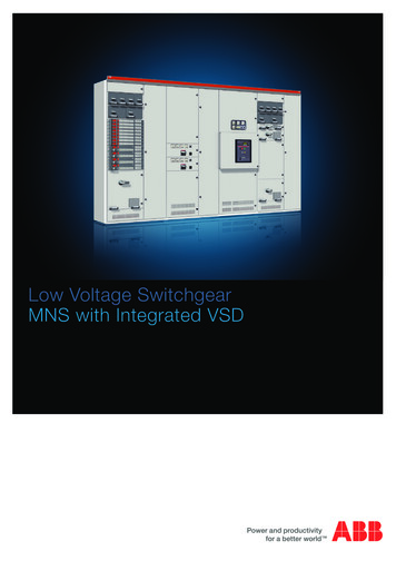
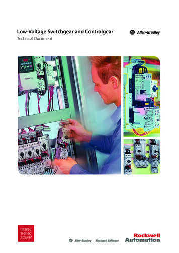
Technical DataStandard finishThe standard finish color is light gray paint (ANSI 61). The standard painting process is a UL approved electrostatic powder coat paint system utilizing polyester powder coat paint. The completed finish has a nominal 2.6mils dry film thickness. The process includes cleaning any grease or deficient phosphate, rinsing, spray coating,oven drying, electrostatic powder spray paint coating, and oven baking.FrameThe basic elements of the frames are: rigid C-channel rails of 12 and 14 gauge thickness galvanized steel withholes at 1” (25 mm) intervals. The parts of the frame are secured with self-tapping screws and require no maintenance. The corner joints are carried out by means of an L shape steel bracket and secured with self-tappingscrews. Lifting eyes are provided as a standard on the roof of the enclosure to allow lifting by the use of a crane.L-Shape bracketC-ChannelAvailable DimensionsThe available widths are: 23.6” (600 mm) [standard], 31.5” (800mm) [standard], 39.4” (1000mm) [standard], and19.7” (500 mm) [optional]. The standard height is: 86.6” (2200 mm) without wire trough. With wire trough theheight is 91.7” (2329.5 mm). The MaxSG height with an overhead lift device is 104.2” (2648mm).The standard depth is 68.9” (1750 mm); optional 59.1” (1500 mm) – restriction to apply.81SXU900121M0201Low Voltage Products & SystemsABB Inc. 888-385-1221 www.abb.us/lowvoltage
Technical DataShipping designRemovable wood shipping base is heat-treated and fumigated; the wood base is provided per shipping split andanchored at four points. The switchgear maximum shipping split is 71” (1800 mm).All breakers will be shipped separately, uninstalled in the switchgear to be installed in the field by others.Barriers and coversSide Panels and rear panels consist of a 3-piece design 14 gauge thickness galvanized steel secured by selftapping torque-head screws. Rear panels are provided with lifting handles and standard finish paint.Option: Rear hinged door with 3-point closing latch system.Low Voltage Products & SystemsABB Inc. 888-385-1221 www.abb.us/lowvoltage91SXU900121M0201
Technical DataThe MaxSG is provided with a two piece slotted top cover. Theslotted holes are there to allow for heat rise ventilation per eachsection. The top panel is made of 14 gauge thickness galvanized steel. A continuous wire tray is placed on top of the roofabove the breaker compartment in order to allow for wiringbetween sections and shipping splits. The dimensions of thecable tray are 5” (125 mm) high by 7.8” (198 mm) wide, allowingspace for contro
MaxSG nameplates meet all standards listed in ANSI C37.20.1. Precautionary labels meet ANSI Z53.4. Stan-dard nameplates for devices are white background with black lettering phenolic screwed on type. Other op-tional nameplates are available upon request. The main system nameplate is a stainless steel screwed on type with self tapping screws. All lettering is engraved. The following information is