Transcription
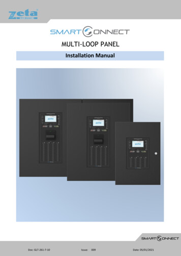
MULTI-LOOP PANELInstallation ManualDoc: GLT-261-7-1Doc: /2018009Date: 05/01/2021
Smart Connect Multi-loop Installation ManualContentsIntroduction . 4About the Smart Connect Multi-loop Fire Alarm System . 4Overall Features . 4EXPLANATION OF ACCESS LEVELS . 5Additional Features . 5Document Conventions . 6Circuits and Zones . 6Wiring Styles . 6System Components . 7Panel Types . 7Panel Modules . 8Control Panel Installation and Dimensions . 10Enclosure Dimensions . 10Panel Construction Details . 10Locating the Fire Alarm Control Panel . 11Mounting the Enclosure . 11Mounting Hole Dimensions . 11Planning Cable Entry . 13Cable Grounding . 13Mains Wiring . 13Battery Wiring . 15Assembling the panel . 18Initial Power Up . 19Module Installation . 19TRM RJ45 Port Address Designation . 20Securing the modules . 20Before Powering the Panel On . 20Power on Procedure . 21Field Wiring . 22Wiring Overview . 22SCM-ACM Field Wiring Connections . 23Wiring recommendations for Alarm Circuits (SCM-ACM) . 24SCM-ACM Specifications . 24Compatible Warning Devices . 25Maximum Warning Devices per Circuit . 25SCM-MIM Field Wiring Connections . 25Wiring Recommendations for Input Circuits (SCM-MIM) . 25SCM-MIM Specifications . 25SCM-RM Field Wiring Connections. 26SCM-RM Specifications. 26SCM-ZMM Field Wiring Connections . 27www.zetaalarmsystems.com2
Smart Connect Multi-loop Installation ManualWiring Recommendations for Zone Monitor Circuits (SCM-ZMM) . 27SCM-ZMM Specifications . 27SCM-NM Field Wiring Connections . 28Wiring Recommendations for Network Wiring (SCM-NM) . 29SCM-NM Specifications . 29SCM-LCM Field Wiring Connections . 30Wiring Recommendations for Loop Card Modules (SCM-LCM) . 31Loop Device Wiring and Device Information . 31SCM-LCM Specifications . 36Compatible Loop Card Devices . 36Power Supply. 37PSU Specifications . 37PSU Fuses . 38Power Supply Status Indications . 38Power Supply Signals . 38Panel Printer. 39Loading/Replacing the Printer Paper Roll . 39Printer Status. 40Printer Maintenance . 40Fault Finding . 40Appendix A: SPECIFICATIONS . 41FUNCTIONS REQUIRED BY EUROPEAN STANDARD EN54-2. 42FUNCTIONS REQUIRED BY EUROPEAN STANDARD EN54-4. 42Appendix B: STANDBY BATTERY REQUIREMENTS . 43Appendix C: LOOP DEVICE ADDRESS SETTING. 44Appendix D: PRODUCT CODES . 47Appendix E: Ground Fault Impedance values. 47www.zetaalarmsystems.com3
Smart Connect Multi-loop Installation ManualIntroductionAbout the Smart Connect Multi-loop Fire Alarm SystemThe Smart Connect Multi-loop Control Panel is a powerful intelligent fire alarm control system with a user friendly 4.3 inch touchscreen display, which has been designed to provide reliable life safety and property protection, while also being easy to install,commission and operate. The Smart Connect Multi-loop system is totally modular which enables it to satisfy any size building fire alarmneeds.By adding intelligent loop modules, the Smart Connect Multi-loop can be upgraded to support up to 3000 addressable devices spreadacross a flexible number of loop cards (maximum of twelve loop cards). The system can also be expanded by adding Form C relayoutput modules, network interface modules, alarm circuit modules, and zone monitor modules for conventional detectors and devices.The Smart Connect Multi-loop system’s touchscreen interface is designed to make status information clear, and system controlfunctions simple to operate. Through the use of function buttons on the systems display the user can easily “SILENCE BUZZER”, “STOPSOUNDERS” or “START SOUNDERS”, or “RESET” the system. The system status presentation is structured to allow the different types ofsystem events (Alarms, technical alarms, and faults) to be viewed independently. Each system event presents the user with a messagedescribing the location of the alarm report and the type of event (manual alarm, smoke, or heat). If additional details about the natureof the alarm report or its location are required, the user can add a text label to the device or zone.The 32-bit microcontroller (MCU) at the heart of Smart Connect Multi-loop rapidly processes logical decisions based on the status ofthe smoke detection and other initiating devices to control the system outputs. The Windows based software ‘Smart Configurator’ isused to configure the system’s operation based on the customer specified operating requirements, and reducecommissioning/installation times.The Smart Connect Multi-loop system continuously checks all software and hardware for proper operation. It checks all control panelelectronic hardware, system memory components, and the system program. A hardware watchdog circuit is provided to ensure thatSystem programs are functioning properly. If a problem develops with the program or processor, the watchdog circuit places theSystem into a fault condition and resets it.The Smart Connect Multi-loop system is equipped with a backup microprocessor on its termination board. To ensure reliableoperation, if the main panel’s CPU stops, the backup CPU will take over and allow the system to still be able to detect and annunciatealarms.The fire alarm operation is always processed as the highest priority over all other operating modes.Overall Features Modular construction allows a panel to be specified using just the required modules.Up to 4, 6 or 12 Loop modules (depending on panel model).4.3” colour touch screen display.Capacity for up to 26 intelligent modules (depending on panel model).Full system redundancy.Extensive Day/Night mode programming.Full cause & effect programming via front of panel or the ‘Smart Configurator’ PC software.250 ZETA addressable MKII devices per loop card.254 available programmable zones.Up to 64 panel peer-to-peer network.Positive Alarm Sequence.Alarm Verification.Alarm circuit special application 24V mode.400W power supply.www.zetaalarmsystems.com4
Smart Connect Multi-loop Installation ManualEXPLANATION OF ACCESS LEVELSThe Smart Connect System has the following access levels.ACCESSLEVELACCESSED BYACCESS METHODFUNCTIONS ACCESSED1General publicDefault stateView PanelOverride delay (if used)Enter user access code(default 0001)2Responsible person Enter user access code(default 0001), and pressMenu Access IconEnter Engineer Password(Default 9999), and pressMenu Access Icon3Installer / Engineer Open Enclosure4Authorised Service EngineerOpen Enclosure & PC S/WStart soundersstop soundersSilence buzzerReset panelAccess User Menu Enable / disable sections of systemTest ModeView Zones / PointsView event logTurn off delayConfigure loopsAssign zonesAssign Text to each pointModify Alarm Operation ProgrammingConfigure network (if fitted)System Diagnostics (LED blink / loop Autocheck)Change passwordsConfigure TCP/IP Port Connect wiring during InstallBattery check during MaintenanceUpdate Cause & Effect programming via USBUpdate Panel Firmware, Add new languageCare should be taken to ensure that the access method for each level is only available to suitably qualified personnel.Additional FeaturesThere is PC configuration software, a mobile monitoring application, a repeater panel and a LED Expander PCB available.PC Configuration Software: Smart ConfiguratorRepeater Panel: SMART/REPApprovals Reference NumbersModel /64SMART26/P/64SMART/REPLPCB 6330w/R01www.zetaalarmsystems.comUKCA Certificate 50832-UKCA-CPR-F1336Included as Ancillaries on main certCPR Certificate 31-CPR-F45172831-CPR-F45182831-CPR-F4519Included as Ancillaries on main cert5
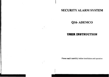
Smart Connect Multi-loop Installation ManualDocument ConventionsCircuits and ZonesCircuit this refers to an actual electrical interface, initiating (detection), indicating (signal), or relay.Zone this is a logical concept for a fire alarm protected area, and will consist of at least one circuit.The terms zone and circuit are used interchangeably throughout this manual.On the Smart Connect Multi-loop, circuits can be either conventional or addressable inputs or outputs. Both hardwired conventionalinputs and outputs, and addressable inputs and outputs may be grouped together to form logical zones.Wiring StylesLoop Circuits have a redundant pathway (powered from both sides of the circuit) and are able to be wired either in the Class Adesignation or in the Class X designation (designed to operate past any a single short circuit with the addition of EN54 listed isolators).Conventional Zone Circuits do not have a redundant path. The SCM-ZMM has 6 Class B circuits and simply terminates at the lastdevice.Alarm Circuits do not have a redundant path. The SCM-ACM has 2 Class B circuits and simply terminates at the last device.Typical SMART Connect Multi-loop Network Fire Alarm Wiringwww.zetaalarmsystems.com6
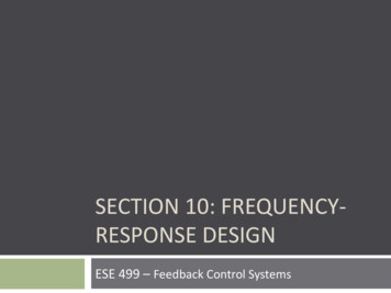
Smart Connect Multi-loop Installation ManualSystem ComponentsPanel 6 W:380mm x H:530mmSpace for up to 6 small modulesSupplied with a 400W 13A PSUSpace for 2 x 12Ah batteries.SMART6/32 W:380mm x H:530mmSpace for up to 6 small modulesEquipped with 32 zone LED expansionSupplied with a 400W 13A PSUSpace for 2 x 12Ah batteries.SMART10/64 W:500mm x H:600mmSpace for up to 10 small modulesEquipped with 64 zone LED expansionSupplied with a 400W 13A PSUSpace for 2 x 38Ah batteriesSMART10/P/64 W:500mm x H:600mmSpace for up to 10 small modulesEquipped with panel printerEquipped with 64 zone LED expansionSupplied with a 400W 13A PSUSpace for 2 x 38Ah batteriesSMART26/64 W:1000mm x H:665mmSpace for up to 26 small modulesEquipped with 64 zone LED expansionSupplied with a 400W 13A PSUSpace for 2 x 38Ah batteries7
Smart Connect Multi-loop Installation ManualSMART26/P/64SMART/REP W:1000mm x H:665mmSpace for up to 26 small modulesEquipped with panel printerEquipped with 64 zone LED expansionSupplied with a 400W 13A PSUSpace for 2 x 38Ah batteries W:300mm x H:200mmSmart Connect RepeaterPlease refer to GLT-261-7-12 SmartConnect Repeater Manual for furtherinformationPanel ModulesModel No.www.zetaalarmsystems.comDescriptionSCM-LCMLoop Card ModuleThe plug-in loop card moduleprovides power for, andhandles communications tothe analogue addressabledevices. It has 4 fault statusLED’s for added fault findingassistance.SCM-ACMAlarm Circuit ModuleThe plug-in alarm circuitmodule provides power for,and handles communicationsto the non-addressablesounder appliances. It has 2 xClass B circuits and can beprogrammed to provide two24v DC auxiliary outputs.SCM-RMMulti Relay OutputA Relay module that isdesigned to be DIN mountedinside of a SMART ConnectMulti-loop panel. It’spowered and interfaced tothe CIE via a RJ45 connection.Can be configured as aprogrammable relay or acommon alarm, commonfault or common tech alarmrelay via the panel settings.TechnicalLoop Voltage: 35V NominalMaximum Loop Current: 450mAMaximum Loop Capacity: 250 AddressesMaximum Loop Length: 2KMMaximum Loop Resistance: 22Ω to , 22Ω - to Maximum SLC Capacitance: 500nFMaximum SLC Baud Rate: 1024 bits per secondCompatible Devices: MKII-AOP, MKII-AOH, MKIIAHR, MKII-AHF, MKII-AHF/CS90, ZAI-MI, ZAIO-MI,ZAZM-MI, ZAIO/230, ZASC-MI, MKII-SSB, MKII-AXT,MKII-AXTB, ZRAP, ZRAPB (EN54 approved)Circuit Voltage: 29VDC NominalMaximum Circuit Current: 500mA per circuitMaximum Circuit Impedance: 4ΩMaximum Circuit Length: Depends on AWGSpecial Applications: Auxiliary 24 VDC Output[Power limited & Unsupervised]End of Line Resistor: 4K7ΩCompatible Devices: ZXT, ZXTB, ZRP, ZRPB (EN54approved)Relay Type: Form C x 3Switching Capacity: 5 A, 30 VDC (resistive)5 A, 250 VAC (general use)Quiescent Current @ 30V: 39.3mARelay Operated Current (LEDs ON): 115.26mA8
Smart Connect Multi-loop Installation ManualSCM-NMwww.zetaalarmsystems.comRS485 NetworkThe SMART Connect Multiloop system network has thefacility to monitor, indicateand control the functions of afire alarm installation, thusallowing signals to bedistributed around a largesite. The network willaccommodate up to 64nodes. The network usesRS485 data communication.Communication Protocol: RS485Maximum Network Size: 64 NodesMaximum Distance Between Nodes: 1KM (using ascreened data cable) or 100M (using a standardfireproof cable)Network Wiring Typologies: Bus or RingNOTE: Only 1 network module allowed per panel. Ifa second module is fitted, it will be powered downwhen the panel starts.SCM-MIMMulti Input UnitAn input module that is usedto monitor and raise alarmfrom any ancillary equipmentsuch as sprinkler flow switch,aspiration detectors,secondary fire control panel,beam detectors, externalpower supplies etc.Input Voltage: 23.7VDC NominalWiring Class: 6 x Class BQuiescent Current @ 30V: 39.3mAInput Max Impedance: 10ΩInput End of Line: 4K7ΩAlarm Triggering Resistor: 1KΩSCM-ZMMZone MonitorA zone monitor that can betypically used forconventional devices and/orfor special detectors that arenot available in addressableform. It has 6 x Class B inputcircuits.Zone Voltage: 26VDC NominalWiring Class: 6 x Class B[Power limited &Supervised]Zone Maximum Line Impedance: 10ΩEnd of Line Resistor: 4K7ΩAlarm Triggering Resistor: 1KΩCompatible Detectors: MKII-OP, MKII-HR, MKII-HF,MKII-HF-CS90, MKII-OH, ZT-CP3 (EN54 approved)SCM-PMRS232 PrinterThe plug-in RS232 modulewill give a Smart ConnectMulti-loop panel the ability tointerface to RS232 serialequipment and devices. Thisis most commonly used toconnect the panel to anRS232 panel printer, or adesktop printer for real timeevent log printing. Themodule also has a 5V auxoutput that is used to providepower to the panel’s internalprinter.Communication Protocol: RS232Baud Rate: 9600Data Bits: 8Parity: NoneStop Bits: 1Compatible Devices: CUSTOM PLUS2 Panel Printer9
Smart Connect Multi-loop Installation ManualControl Panel Installation and DimensionsEnclosure DimensionsSee table 1 for full dimensions see table 1.Table ckouts12828BottomKnockouts4420MaxBatterySize2 x 12Ah2 x 38Ah2 x 38AhPanel Construction DetailsAll components are manufactured from Zintec.Large and Medium Smart Multi-loop EnclosuresBack box and door 1.5 mmDoor plate 0.9 mmAll internal parts are 0.9 mmSmall Smart Multi-loop EnclosureAll parts are 0.9 mmSmart Repeater EnclosureAll parts 0.9 mm.The paint colour for the main box and door is RAL9005 Black Leatherette (Black version).The internals are RAL9005 Black Leatherette.www.zetaalarmsystems.com10
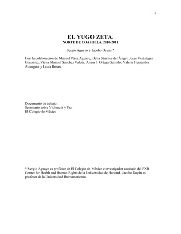
Smart Connect Multi-loop Installation ManualThe control cabinet can be semi flushed into a wall or surface mounted.Locating the Fire Alarm Control PanelThe control panel should be installed per BS5839-1:2017 recommendations: The panel should be close to the main entrance of the building, so that it can be viewed by any fire-fighting personnel entering thebuilding. It should be fitted to a sturdy wall that will not flex unnecessarily.It should ideally be mounted at eye level, for it to be viewed without need of a ladder.It should be installed in a dry, weatherproof place, preferably NOT in direct sunlight.It should be easily accessible, so that the responsible person can perform their regular fire alarm checks.The panel must be in a clean, dry position, which is not subject to excessive shock or vibration and at least 2 meters away from pagersystems or any other radio transmitting equipment. The operating temperature range is -5 C (23 F) to 40 C (104 F); maximum humidityis 95%. The panel will withstand vibrations between 5 & 150 Hz.Mounting the EnclosureFix the enclosure to the wall using all the mounting points provided:SMART6: 4 x Mounting Points. See Fig 1SMART10: 4 x Mounting Points See Fig 2SMART26: 6 x Mounting Points. See Fig 3Check the build and condition of the wall to decide a suitable screw fixing. The mounting holes are designed for No 8 roundhead orcountersunk woodscrews (or similar). Remove any debris from the enclosure. Take care not to damage the FACP during installation.ATTENTION: DO NOT DRILL ANY ENTRY HOLES INTO THE PSU SECTION OF THE ENCLOSURE WHICH IS LOCATED ON THE LEFTHAND SIDE OF THE CONTROL PANEL CABINET.Mounting Hole DimensionsFig 1www.zetaalarmsystems.com11
Smart Connect Multi-loop Installation ManualFig 2Fig 3www.zetaalarmsystems.com12
Smart Connect Multi-loop Installation ManualPlanning Cable EntryThe Knock-out cable entries can be easily removed by tapping with a suitable screwdriver or chisel from outside the control panel box.Alternatively, the entry can be drilled out, using a 20mm hole cutter. Care should be taken if using a drill. Consider removing the PCBsto prevent damaging them.The SMART Connect Multi-loop comes with many cable entry holes. If another entry hole is required, it is strongly recommended thatthe panel door is removed to avoid accidental damage. Also, the power supply and termination board should be removed and stored ina safe place. This would also help while fixing the back box to the wall.ATTENTION: DO NOT DRILL ANY ENTRY HOLES INTO THE PSU SECTION OF THE ENCLOSURE.Cable GroundingThe panel is provided earth bars located along the top of the panel for grounding incoming wiring if needed.The SMART6 panel has 1 x 12 way Earth barThe SMART10 panel has 2 x 12 way Earth barThe SMART26 panel has 3 x 12 way Earth barMains WiringNote: The AC (mains) input wiring, and the back-up battery connections are non-power-limited. All other connections on theSMART connect multi-loop panel are power limited. Ensure that a minimum ¼” separation exists between non-power-limited andpower-limited circuits.www.zetaalarmsystems.com13
Smart Connect Multi-loop Installation ManualRecommendationsThe Mains supply to the FACP is fixed wiring, using Fire resisting 3-core cable (Between 1 mm² and 2.5mm²), or equivalent, fed from anisolating double pole switch fused spur, and fused at 5A. This should be secure from unauthorized operation and be marked ‘FIREALARM: DO NOT SWITCH OFF’. The supply must be exclusive to the Fire Panel.Connecting the Mains PowerThe AC Live (L), Earth (E) and Neutral (N) connections are marked on the power supply cage. It is essential that the mains Earth cable isconnected to the PSU’s Earth terminal. The incoming mains cable should be kept separate from the loop card cables to help minimisemains interference.ATTENTION: MAKE SURE ANY SPARE ENTRY HOLES THAT HAVE BEEN OPENED, BUT NOT USED ARE COVERED WITH SUITABLEGROMMETS OR BLANKING SCREWS.It is advisable to apply power to the panel before connecting any devices, to check for correct operation, and to familiarise yourself
devices. It has 4 fault status LED [s for added fault finding assistance. Loop Voltage: 35V Nominal Maximum Loop Current: 450mA Maximum Loop Capacity: 250 Addresses Maximum Loop Length: 2KM Maximum Loop Resistance: 22Ω to , 22Ω - to - Maximum SLC Capacitance: 500nF Maximum SLC Baud Rate: 1024 bits per second