Transcription
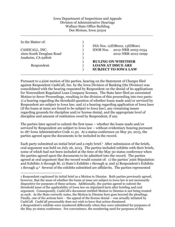
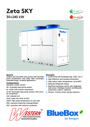
Zeta SKY30 240 kWGeneralChillers and reversible heat pumps with hermeticscroll compressors and plate heat exchanger.Extended range, versatile applications.ConfigurationsStandard: Chiller versionHP: reversible heat pump versionHi: chiller with inverter compressorHi HP: Reversible heat pump version, with inverter compressor/LN: silenced unit/SLN: super low noise version/HWT: High water temperature on user side/DS: execution featuring a desuperheater/DC: execution with recovery condenserStrengths Conforming with Ecodesign Reg. 2281, tier 2 High efficiency and compact dimensions High output water temperature: up to 60 C Reduced refrigerant charge BlueThink advanced control with integratedweb server. Multilogic function and Blueye supervision system. (options) Flowzer: inverter driven pumps (options)
Zeta SKYDescription of accessories10Technical specifications31Ecodesign53Electrical specifications65Hydraulic modules79Pump data82User-side exchanger flow rate fields83Operating limits84Noise levels92Configurations that are not possible96Installation advice98Refrigerant circuit accessoriesFan accessoriesHydraulic circuit accessoriesElectrical accessoriesNetwork accessoriesOther SKY101213212629R7 - Zeta SKY R7 SLNR7 - Zeta SKY R7 SLNHP R7 - Zeta SKY HP R7 SLNHi R7 - Zeta SKY Hi R7 SLNHi HP R7 - Zeta SKY Hi HP R7 SLNHP R5 - Zeta SKY HP R5 SLN848586888990Water characteristicsGlycol mixturesMinimum water content in the systemInstallation siteInstallations that require the use of treated coilsAeraulic head losses and options available for the ventilating section 989899100101102 1
2
Zeta SKYZeta SKY is a large range of high efficiency chillers and reversible heat pumps featuring hermetic scroll compressorsand an air source, suitable for both comfort and processapplications. Chiller versions are designed for the production of chilled water at temperatures ranging between-8 C up to 20 C, with outside temperature from -20 C upto 48 C. Heat pump versions are designed for the production of hot water up to 60 C, and operate with outsidetemperature down to -15 C. Versions featuring a variablespeed inverter compressor are designed to maximise seasonal efficiency. The entire range is characterised by highcompactness and a reduced refrigerant charge. Zeta SKYuses low GWP refrigerants that have a low environmentalimpact.REFRIGERANTChiller models from the Zeta Sky series are available withrefrigerant R32.Heat pump models from the Zeta Sky series are availablewith refrigerant R32 or R454B.Acronym “R7” indicates the need to use refrigerant R32and it shows that the refrigerant has a GWP level below700.Acronym “R5” indicates the need to use refrigerant R454Band it shows that the refrigerant has a GWP level below500.Refrigerant R32 (GWP 677*)The refrigerant consists in pure gas.R32 is classified as a Group 1 fluid under PED.It is also classified as A2L under the ASHRAE Standard34, i.e. non-toxic; mildly flammable.Refrigerant R454B (GWP 466*)The refrigerant consists in a blend of R32 (69%) andR1234yf (31%), with limited temperature glide.R454B is classified as a Group 1 fluid under PED.It is also classified as A2L under the ASHRAE Standard34, i.e. non-toxic; mildly flammable.The excellent GWP value may be an advantage in projectswhere: min. targets are adopted for the containment of the environmental footprint; it is possible to receive incentives or other benefits thatare applicable in some countries or are connected tospecific plant design criteria.This also goes to the benefit of unit installation, commissioning and maintenance as it reduces the overall management costs.(*) GWP (AR5), pursuant to IPCC V, evaluated over a spanof 100 years. STRUCTUREThe structure of the unit is made of galvanized sheet-ironcoated with polyester powder in RAL 5017/7035 at 180 C,which makes it highly resistant to weather conditions.The structure is a load-bearing frame, with removable panelling lined with sound absorbing expanded polyurethanematting.All screws and bolts are stainless steel.COMPRESSORSZeta SKY R7 - Zeta SKY HP R7 - Zeta SKY HPR5The compressors are hermetic, orbiting spiral scroll compressors connected in tandem, with either one or two circuits. They are provided with thermal overload protectionby internal Klixon or external Kriwan module (depending on the model) and with oil equalization line. All thecompressors are fitted as standard with crankcase heater.The compressors are enclosed in a dedicated technicalcompartment, which can be accessed by removing the panelling to allow maintenance operations to be carried outeven with units running.Zeta SKY Hi R7 - Zeta SKY Hi HP R7Depending on the model, there are the following compressor configurations:models with just one compressor (x.1) use a single modulating compressormodels with two compressors (x.2) use one modulatingcompressor connected in tandem with one ON/OFF compressorThe modulating compressors are hermetic scroll compressors with permanent-magnet brushless motor and are fitted with oil level sight glass.The speed of the modulating compressor is varied, depending on the total heat load, roughly between 30 and 105rps. 30rps and 105rps Its nominal capacity relates to aspeed of 90rps. 90rps.The speed of rotation of the compressor is variable in therange 1.800 6.300 rpm.The modulating compressors are controlled through DCinverter. This also has the following functions: management of acceleration and deceleration ramps management of the operating envelope of the modulating compressor management of the alarms and safety devices of themodulating compressorThe use of a modulating compressor allows the total inrush current to be reduced because it is always startedwith an acceleration ramp. For models with two or threecompressors, the starting of the ON/OFF compressors willalways take place with the modulating compressor running at low speed, again in order to reduce the inrushcurrent of the unit to a minimum.The ON/OFF compressors are hermetic orbiting spiralscroll compressors and are fitted with oil level sight glass.For units with two compressors, there is also an oil equalization line. 3
SOURCE-SIDE HEAT EXCHANGER(for chiller unit)The exchangers are made with microchannel aluminiumcoils.Thanks to continuous research in the alloys field, andsophisticated production methods, microchannel coils aremade using specific aluminium alloys for the tubes and forthe fins. This allows the effects of galvanic corrosion tobe drastically reduced to always ensure protection of thetubes that confine the refrigerant. Tubes and fins are alsosubjected to SilFLUX coating processes (or equivalent) orhave zinc added to further increase their corrosion resistance.The use of microchannel coils, as opposed to conventionalcopper/aluminium coils, reduces the total weight of theunit and reduces the refrigerant charge.Options are available for installation in environments witha particularly aggressive atmosphere or in coastal or highly industrialized areas. See section: "Description of accessories".(for HP units)The exchangers are made with finned pack coils with copper tubes and aluminium fins.The coils have an increased fin pitch to reduce frost formation and to facilitate the outflow of condensed waterduring defrosting.Options are available for installation in environments witha particularly aggressive atmosphere or in coastal or highly industrialized areas. See section: "Description of accessories".FANSThe fans are axial fans, directly coupled to a 6-poleelectric motor, with integrated thermal overload protection(Klixon ) and IP 54 protection rating.The fan includes the shroud, designed to optimize its efficiency and reduce noise emission to a minimum, and thesafety guard.The control manages the speed of the fans through a phase cutting speed adjuster, in order to optimize the operating conditions and efficiency of the unit.The fan speed regulator is supplied standardly.This control also has the effect of reducing the noise levelof the unit: in fact, the typical conditions under which thecontrol will be modulating the speed of the fans are thoseof the night, spring and autumn.For units equipped with EC fans (option), the same function is carried out using the electronically commutatedmotor of the fans.4 USER-SIDE HEAT EXCHANGERThe exchanger is a braze-welded stainless steel plate heatexchanger, insulated with a shroud of closed-cell insulating material.The exchanger is also equipped with thermostat-controlledanti-freeze heater to protect it from ice formation whenthe unit is not running.REFRIGERANT CIRCUITZeta SKY R7 - Zeta SKY HP R7 - Zeta SKY HP R5Each refrigerant circuit of the basic unit comprises: valve on the liquid line 4-way reversing valve (applies to HP versions only) valve on delivery line (applies to HP versions only) liquid receiver charging sockets liquid sight glass replaceable solid cartridge dehydrator filter (except forsizes 3.2, 4.2 and 5.2 where the filter is a weld-on filter) thermostatic expansion valve with pressure equalization high and low pressure switchesThe pipes of the circuit and the exchanger are insulatedwith extruded closed-cell expanded elastomer.As an accessory, all the units can be fitted with an electronic expansion valve that allows machine stability to be reached more quickly and better superheating control thanthe mechanical expansion valve, to maximize the use ofthe evaporator in all load conditions.Zeta SKY Hi R7 - Zeta SKY Hi HP R7Each refrigerant circuit of the basic unit comprises: valve on the liquid line 4-way reversing valve (applies to HP versions only) valve on delivery line (applies to HP versions only) liquid receiver charging sockets liquid sight glass replaceable solid cartridge filter drier (except for sizes3.1, 4.1 and 6.2 where the filter is a weld-on filter) electronically-controlled thermostatic expansion valve high and low pressure switchesThe pipes of the circuit and the exchanger are insulatedwith extruded closed-cell expanded elastomer.ELECTRICAL CONTROL PANELThe electrical control panel is made in a painted galvanized sheet-iron box with forced ventilation and IP54 protection rating.
The electrical control panel of the basic unit comprises: main disconnect switch automatic circuit breakers for compressors with fixedcalibration fuses for protecting the fans and auxiliary circuits fan contactors phase-cutting fan speed adjuster thermal magnetic circuit breakers for pumps (if present) phase monitor potential-free general alarm contacts single potential free operating contacts for compressors, fans and pumps (when present) digital input for general ON/OFF summer/winter selection by digital input (only for HPunits) external air temperature probe microprocessor controller with display accessible fromthe outsideAll the electrical cables inside the panel are numberedand the terminal board dedicated to the customer's connections is coloured orange so that it can be quickly identified in the panel.Zeta SKY R7 - Zeta SKY HP R7 - Zeta SKY HPR5: The power supply of the unit is 400V/3 N/50Hz forthe following models:from size 3.2 up to size 8.2The power supply of the unit is 400V/3 /50Hz for the following models: from size 9.2 up to size 16.4Zeta SKY Hi R7 - Zeta SKY Hi HP R7 The power supply of the unit is 400V/3 N/50Hz forthe following models:from size 3.1 up to size 8.2The power supply of the unit is 400V/3 /50Hz for the following models: from size 10.2 up to size 12.2CONTROL BLUETHINKZeta SKY R7 - Zeta SKY HP R7 - Zeta SKY HPR5:The unit is supplied as standard with parametric control.The advanced control can be requested as accessory.Main controller functions parametricThe control allows the following functions: water temperature adjustment, with control of the water entering the user-side heat exchanger freeze protection compressor timings automatic rotation of compressor starting sequence recording of the alarm log RS485 serial port with Modbus protocol digital input for general ON/OFF digital input for Summer/Winter selection (only for HPunits) For further details on available functions and on displayedinformation, refer to the specific documentation of thecontroller.By default, the serial connections present as standard areenabled only for reading from BMS. Enabling of writingfrom BMS is to be requested when ordering.Main controller functions advancedThe control allows the following functions: water temperature adjustment, with control of the water entering the user-side heat exchanger freeze protection compressor timings automatic rotation of compressor starting sequence recording of the log of all machine inputs, outputs andstates automatic rotation of compressor starting sequence recording of the alarm log RS485 serial port with Modbus protocol Ethernet serial port with Modbus protocol and integrated web server preloaded web page digital input for general ON/OFF digital input for Summer/Winter selection (only for HPunits)For further details on available functions and on displayedinformation, refer to the specific documentation of thecontroller.By default, the serial connections present as standard areenabled only for reading from BMS. Enabling of writingfrom BMS is to be requested when ordering.Main functions of the webserver (only for units with advanced control)As standard, the Bluethink controller integrates a webserver with a preloaded web page that is accessed viapassword.The web page allows the following functions to be carriedout (some of these are available only for users with advanced level rights): display of the main functions of the unit such as unitserial n , size, refrigerant display of the general status of the machine: water inlet and outlet temperatures, external air temperature,mode (chiller or heat pump), evaporating and condensing pressures, suction and discharge temperatures display of the status of compressors, pumps, expansionvalves display in real time of the graphs of the main quantities display of the graphs of logged quantities display of alarm log management of users on several levels remote ON/OFF remote set point change remote time band change remote summer winter mode selection (only for HP units)Zeta SKY Hi R7 - Zeta SKY Hi HP R7The unit is supplied as standard with an advanced controller. 5
The control allows the following functions: water temperature adjustment, with control of the water entering the user-side heat exchanger freeze protection compressor timings automatic rotation of compressor starting sequence recording of the log of all machine inputs, outputs andstates automatic rotation of compressor starting sequence recording of the alarm log RS485 serial port with Modbus protocol Ethernet serial port with Modbus protocol and integrated web server preloaded web page digital input for general ON/OFF digital input for Summer/Winter selectionFor further details on available functions and on displayedinformation, refer to the specific documentation of thecontroller.By default, the serial connections present as standard areenabled only for reading from BMS. Enabling of writingfrom BMS is to be requested when ordering.Main functions of the webserver (only for units with advanced control)As standard, the Bluethink controller integrates a webserver with a preloaded web page that is accessed viapassword.The web page allows the following functions to be carriedout (some of these are available only for users with advanced level rights): display of the main functions of the unit such as unitserial n , size, refrigerant display of the general status of the machine: water inlet and outlet temperatures, external air temperature,mode (chiller or heat pump), evaporating and condensing pressures, suction and discharge temperatures display of the status of compressors, pumps, expansionvalves display in real time of the graphs of the main quantities display of the graphs of logged quantities display of alarm log management of users on several levels remote ON/OFF remote set point change remote time band change remote summer winter mode selection water inlet and outlet temperatureset temperature and differential set pointsdescription of alarmshour meter of operation and number of start-ups of theunit, the compressors and the pumps (if present) high and low pressure values, and relevant condensingand evaporating temperatures external air temperature superheating at compressor suction.Management of defrost cycles(only for HP units)For defrost management, the control of the unit uses asliding intervention threshold, depending on the pressuresinside the unit and the external air temperature. By putting together all this information, the control can identifythe presence of ice on the coil and activates the defrosting sequence only when necessary, so as to maximizethe energy efficiency of the unit.Sliding management of the defrost threshold ensures that,as the absolute humidity of outdoor air decreases, the frequency of the defrost cycles gradually decreases becausethey are carried out only when the ice formed on the coilactually penalizes performance.The defrost cycle is fully automatic: during the initial stage, a defrost is carried out by cycle reversal with the fansstopped. As soon as the frost on the coil has molten to asuitable level, the unit resumes operation in heat pumpmode.OPTIONS/HWT: High water temperature on user sideThis option is only available for Zeta SKY model HP R7.The HWT option is designed to expand the work range ofthe unit.The BlueThink technology is used to check the outputtemperature of the compressor, which enables expandingthe operating limits and generating hot water up to 60 C.The check is performed using the electronically-controlledexpansion valve./HAT: unit for high external air temperaturesThe HAT option is designed to expand the work range ofthe unit./DC: unit with total recovery condenserIn addition to the set-up of a chiller only unit, /DC unitscomprise:Human-Machine InterfaceThe control has a graphic display that allows the followinginformation to be displayed:6
a heat recovery condenser for recovering 100% ofthe condensation heat on each refrigerant circuit. Theexchanger is a brazed plate heat exchanger; for dualcircuit units, the heat exchangers are to be manifoldedoutside the unit (by the customer) temperature probe at the inlet of the heat recoveryheat exchanger; for dual circuit units, the probe is supplied with the unit and is to be positioned on the heatexchanger inlet manifold (by the customer) liquid receiver for each refrigerant circuit with systemfor emptying the refrigerant from the condensing coil potential free contact in the electrical control panel foractivation of recovery.When required by the system, through the closing of acontact, the control automatically manages activation ofrecovery. Recovery management is carried out through acontrol on the temperature of the return water. The control also automatically manages safety deactivation of recovery if the condensing pressure becomes too high, andchanges to using the condensing coils.This option is not available for /HP unitsAn illustrative graph is shown below in which, as the ambient temperature changes, (Tair) and as the temperature of the water leaving the heat recovery heat exchangerchanges, (Tw,out DS), the percentage of recovered heat isshown as an indication (Recovery ratio).Condensation heat recovery is a function of size, versionand operating conditions.The percentage of recovered heat is calculated as the ratiobetween recovered heat flow to the desuperheater and theheat flow to the condenser under nominal conditions, therefore evaporator inlet-outlet water temperature 12-7 C.In the following graph, a constant temperature delta of5 C between water inlet and outlet at the heat recoveryheat exchanger has been considered./DS: unit with desuperheater/DS units comprise (for each refrigerant circuit) anexchanger for condensation heat recovery of up to 20%(depending on size, version and operating conditions),placed in series with the condensing coil. The exchangeris a braze-welded plate heat exchanger. For multi-circuitunits, the exchangers are to be manifolded outside theunit (by the customer).The desuperheater can be used during operation in coolingmode. However, it can also be used in heating mode oncondition that the following measures are taken: a valve (either 2- or 3-way) must be installed on thedesuperheater water circuit; the valve must be monitored using a temperature control system; the valve must be operated to regulate the temperatureof the input water into the desuperheater IWTds.First, enter the unit heating setpoint, which correspondsto the temperature of water delivered to the heating unit LWTu Heating. Then set the condition below: IWTds LWTu Heating 10 [K]The valve, the control systems and their installation, setupoperations, etc. are the responsibility of the client. If heatrecovery is not required during operation in heat pumpmode, or where the above requirements are not met, thewater circuit of the desuperheater must be shut off. Desuperheater operation in heat pump mode reduces the heating capacity transferred from the unit to the user’s hydronic circuit. When a desuperheater is fitted, irrespectiveof it running in either cooling or heating mode, the max.temperature of water delivered to the heating unit (LWTuHeating) is reduced, as described in the section “Operating limits”. /LN: silenced unitIn the unit with /LN option, all the compressors are enclosed in a compartment that is fully soundproofed withsound absorbing material and soundproofing material./SLN: super low noise unitUnit versions SLN are characterised by the use of a soundproofed compressor compartment, fans with a speedadjuster, and a reduced air flow rate. The speed reductionof the fans is such that, under nominal operating conditions, the air flow rate and noise level are lower than thoseof the basic version of the unit.In any case, the use of the speed adjuster to reduce theair flow rate allows rotation of the fans at maximum speedwhen external air temperature conditions are particularlycritical and therefore guarantees the same operating limitsas the high efficiency version.Also, for SLN/HP version units working in heat pumpmode, the fans always operate at 100% speed and therefore guarantee the same performance levels as the highefficiency versions.HYDRAULIC MODULESAll units can be fitted with hydraulic module in variousconfigurations: /1P: hydraulic module with one pump /2P: hydraulic module with two pumps /1PS: hydraulic module with one pump and buffer tank /2PS: hydraulic module with two pumps and buffer tank 7
The following are also available: modules /1Pr, /2Pr, /1PrS e /2PrS that have pumps withreduced available discharge head modules /1PM, /2PM, /1PMS and /2PMS that have pumps with increased available discharge head modules /1PG, /2PG, /1PGS and /2PGS that have pumps suitable for operating with glycol up to 40%Hydraulic modules with one pump have: one pump an expansion vesselHydraulic modules with two pumps have: two pumps a check valve on the delivery side of each pump an expansion vesselIn the version with 2 pumps, these are always with one onstandby while the other is working. Switching over between the pumps is automatic and is done by time (to balance the hours of operation of each one) or in the event offailure.Hydraulic modules with tank also have: a gate valve at the inlet of the pump or the suctionmanifold a tank with drain valve and air valveRefer to the table of configurations that are not possible tocheck for availability of specific set-ups.All the hydraulic circuit components are fully insulated,except for: drain valves venting valves tank plugs safety valves expansion vessel probe pocketsCONTROLS AND SAFETY DEVICESAll the units are fitted with the following control and safetycomponents: user-side water temperature probe antifreeze probe on the user side heat exchanger high pressure switch with manual reset low pressure safety device with automatic reset, for alimited number of occurrences, managed by the controller compressor overtemperature protection fan overtemperature protection differential flow switch8 TESTINGAll the units are factory-tested and supplied complete withoil and refrigerant.PACKAGINGThe unit is made and shipped on a wooden pallet that allows the unit to be handled using a forklift truck.The unit is wrapped in a protective transparent polyethylene stretch film.CERTIFICATIONS AND REFERENCESTANDARDSThe manufacturer has implemented and keeps the Management Systems listed below and it is certified againstthem: Quality Management System according to standard UNIEN ISO 9000; Environmental Management System according to standard UNI EN ISO 14000; Health and Safety Management System according tostandard BS OHSAS 18000 (as converted into UNI ENISO 45000).These management systems ensure that the companyputs in place any and all actions and initiatives to defineand monitor the standards defined by its Management,which are stated in its Quality, Environmental and Safetypolicies.To meet the safety requirements, the unit was designedand manufactured in compliance with the directives andproduct regulations below: PED Directive: safety criteria to be followed when designing pressure equipment; Machinery Directive: safety criteria to be followed whendesigning machinery; Low Voltage Directive: safety criteria to be followedwhen designing electrical machine parts; Electromagnetic Compatibility Directive: electromagnetic compatibility criteria to be followed when designingelectrical machine parts; WEEE Directive: criteria for product management at theend of its life cycle as waste with a view to environmental protection.The units are manufactured, tested and checked with reference to the European standards specified in the Declaration of CE Conformity, in accordance with the requirements and procedures of our Quality System.The installation, use and storage of units featuring mildlyflammable refrigerants (A2L pursuant to standard ASHRAE34), such as R32 and R454B, must meet the Europeanstandards and regulations and the local laws, where applicable.For further details, please refer to the "Instruction manualfor operation and maintenance”.
Responsibilities and obligations exclusive tothe installer: to carry out a specific risk assessment according to theEuropean regulations/standards above and/or the locallaws in order to define the necessary measures for conformity; to comply with the requirements and to take the measures resulting from the outcomes of the risk assessment,pursuant to the relevant regulations and standards. 9
DESCRIPTION OF ACCESSORIESSome accessories may be incompatible with each other even if not expressly indicated.Refrigerant circuit accessoriesBCBTBKDVSMAFRRGRIC10Capacitive backup battery for electronic expansion valveWhen the compressors stop, the controller always closes the electronic expansion valve to prevent dangerousrefrigerant migration. The presence of the backup battery ensures that the electronic valve is kept in closedposition even when there is no power supplyThis option uses a condenser as energy storage, and not an ordinary coil. In this way, it is not affected by thememory effect of normal coils and the need for maintenance is avoided.Applies to units with advanced controller.Backup battery for electronic expansion valveWhen the compressors stop, the controller always closes the electronic expansion valve to prevent dangerousrefrigerant migration. The presence of the backup battery ensures that the electronic valve is kept in closedposition even when there is no power supplyThis option uses a condenser as energy storage, and not an ordinary coil. In this way, it is not affected by thememory effect of normal coils and the need for maintenance is avoided.Applies to units with parametric controller.Brine KitThis accessory is compulsory if a water temperature set point lower than or equal to 3 C is used (if the unitis provided with double set point or variable set point, the lower set point is considered).The accessory consists of increased insulation and suitable sizing and calibration of some components.The inlet and outlet temperatures of the user-side exchanger must be given on ordering to allow correct setting of the alarm parameters and verification of the sizing of the expansion valve.The cooling set point can then be changed by the customer in an interval that, compared to the set point givenon ordering, ranges from -1K up to the allowed limit temperature.The unit will be optimized to work at the set point temperature given on ordering. For different set points, thecooling capacity provided and the level of efficiency of the machine could decrease and move away from theseconditions.Double safety valveWith this accessory, instead of each individual safety valve per circuit, there is a "candelabrum" with two safetyvalves and a diverter valve for choosing the valve in operation. This allows the safety valves to be replacedwithout having to drain the machine and without having to stop it.Pressure gaugesThe operating pressures of each circuit of the unit can be displayed on the control by accessing the relevantscreens. Also, the machine can be fitted with pressure gauges (two for each circuit) installed in a clearly visibleposition. These allow reading in real time of the working pressures of the refrigerant gas on the low pressureside and on the high pressure side of each refrigerant circuit.Fan speed adjusterThe control manages the speed of the fans through a phase cutting speed adjuster, in order to optimize theoperating conditions and efficiency of the unit.This control also has the effect of reducing the noise level of the unit
Zeta SKY R7 - Zeta SKY HP R7 - Zeta SKY HP R5 The compressors are hermetic, orbiting spiral scroll com-pressors connected in tandem, with either one or two cir-cuits. They are provided with thermal overload protection by internal Klixon or external Kriwan module (depen-ding on the model) and with oil equalization line. All the