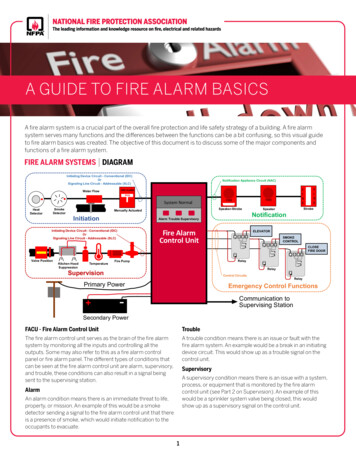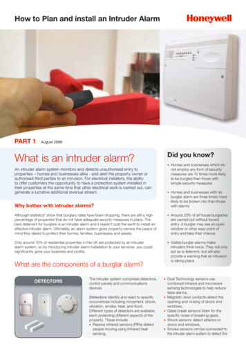
Transcription
Control Panel-Based AlarmSystemInstallation · Programming · OperatingKeep this manual safe for reference and future maintenanceYale Consumer Helplinecontrol panel alarm manual.indd 101902 63599824/11/06 18:47:40
IntroductionGeneral System OverviewThank you for choosing the Yale Wireless AlarmSystem. This simple to install system has beendesigned with the user in mind.Two window stickers are included in the pack.Please stick them in a front and rear window.No connectionsAll the components are self contained and noconnections are needed between the units. There isno need to damage the home decor, lift carpets orrun cables.Number of devicesYou can install up to 20 devices in the system.As well as extra door/window contacts, PIRsand smoke detectors, you can add keyfobremote controls and keypads for added controlconvenience.Long battery lifeThere is no need to wire into the mains supply orseek the services of a qualified electrician. Thecontrol unit is powered by a plug top supply andall other components are powered by battery (allbatteries included).Batteries will operate for 2 years or more before theyneed changing. Regular testing and battery changes(when notified by the system) will ensure reliabilityand peace of mind. Please note that alkalinebatteries must be used as replacements.Take care of your safetyDisplay extreme caution when using ladders orsteps, please follow manufacturer’s instructions.Be careful when using hand and power tools andfollow the manufacturer’s guidelines when usingthem. Take care that the correct tools are used.Wear goggles or protective clothing where required.The external Siren is extremely loud, please ensureyou replace the cover and retreat to a safe distancebefore testing.Caution (kits with telephone dialler function only)The dialling facilities must only be used with personswho have consented to being contacted by thesystem.The system is not to be used to make 999emergency calls directly. Yale do not holdresponsibility for any actions taken by emergencyservices for incorrect use of the dialling facility.Calling for helpYale have a helpline team who are there to offeradvice or solve problems over the phone.Yale Consumer Helpline 01902 635998Service available 9am-5pm Monday to Friday.Tamper proof systemThe security detectors, control panel and externalsiren are ‘tamper’ protected. Any unauthorisedtampering with these items will result in an alarm.This feature can be turned off by the user when abattery change is required.Unique telephone linksThe siren has a sounder and strobe. If for anyreason it is not responded to, the system willphone three allocated numbers to secure aresponse. Information and illustrations are subject to change within this document. Yale reserves the right to alter the specification and product designat anytime without notice. Yale is a registered trademark. 2006 ASSA ABLOY. All rights reserved.control panel alarm manual.indd 224/11/06 18:47:41
ContentsRecommended Installation SequenceContentsWe recommend you follow the simple installsequence, headings numbered 1-6.1Location planning42Unpack all the parts63First Time Easy Install84Mounting alarm devices105Control Panel Menu System in Detail146Using the System20Adding and using Accessories22Changing the batteries24Troubleshooting26Specifications28Key pointsBack coverAccessories availableHSA6020 Passive infra-red (PIR) detectorHSA6030 3 x Passive infra-red (PIR) detectorsHSA6010 Door/window contactHSA6060 Remote control (keyfob)HSA6080 Remote keypadHSA3045 Help buttonHSA3070 Smoke detector control panel alarm manual.indd 324/11/06 18:47:42
1Location planningWork out the best places to locate the devices for maximum protection. Having chosen thelocations do not mount at this stage.Home and Away Mode PlanningThe home arming mode allows the premises to bepart armed so that no one can get inside withoutwarning the occupier, yet the person already insidethe house can move freely without triggering thealarm. For example the downstairs of a house canbe armed while upstairs can be disarmed allowingthe user to go to bed without causing an alarm.If this feature is to be used, then it should beplanned now, before installation.Decide what areas can be occupied when in homearming mode, the sensors for these areas shouldbe programmed to home omit; and the sensorsactivated on the path to access the control unitshould be to be set to either Entry or Away Entry asexplained on page 15.Keypad remote control accessoryWhen used as second keypad, it is ideal inbedrooms or at the top of a stairwell so theground floor can be armed when going to bed forthe night. Or, at a side or back door for alternativeentry. Mount at chest height for ease of use Designed for indoor use only Keypad should be accessible from a protectedentry/exit point Ensure that the keypad is not visible from theoutside of the premises.Operating RangeAll devices must be within 30 metres of the controlunit and must not be mounted on or near largemetal objects. Avoid obvious sources of electricalinterference such as fridges and microwave ovens.Tamper SwitchesWhen mounting devices ensure that any tamperswitches close fully. On uneven surfaces it may benecessary to place packing behind the switch forreliable operation.Extend The SystemExtend the system in the future to increase yoursecurity or as your needs change.For example, add extra PIR detectors andextra door/window contacts.Help button accessoryThe help button provides extra protection for youand your family. When help is needed the buttoncan activate your alarm immediately - even whenthe system is disarmed. Mount on bedroom wall or by the front door Not clearly visible to an intruder Easily accessible Out of reach of children control panel alarm manual.indd 424/11/06 18:47:44
Smoke detector Mount in the middle of the ceiling at the top ofa stairwell, or on the centre of hallway ceilingswhere smoke would most likely be detected. Do not mount in corners or above cookingappliances and heaters. Install additional detectors if there are closeddoors preventing smoke from reachingdetectors.SirenChoose a position on an external wall where thesiren would be most prominent. Mount as high aspossible, out of easy reach.Door/Window contactSelect a door that will be the main point of entryand exit, usually your front door. Mount as high as possible Do not aim a PIR at this door or window9ALEKeyfob remote control accessory9ALE2!PR ABC DEF GHI JKL MNO PQRS TUV WXYZ Can be used inside or outside the property andcan be kept on your keyring.9ALE9ALE29ALE2!PR!PR ABC DEF ABC DEF GHI JKL MNO GHI JKL MNO PQRS TUV WXYZ PQRS TUV WXYZ PIR movement detector Mount in a position such that an intruder wouldnormally move across the PIRs field of view. Height should be between 1.7 and 2.3 metresabove floor level. Location in a corner will ensure wider roomcoverage. Do not mount the PIR where its field of view willbe obstructed e.g. by curtains, ornaments etc. Do not point directly at sources of heat e.g. firesor boilers, and do not position directly aboveradiators. Avoid mounting the PIR directly facing awindow. Do not point the PIR at a door protected by adoor/window contact.9ALE2!Control unit Ensure the control unit is accessible whenentering through a protected entry/exit point. Avoid mounting the control unit where it wouldbe visible from the outside of the premises Locate by a mains socket and telephone point.PR ABC DEF GHI JKL MNO PQRS TUV WXYZ control panel alarm manual.indd 5 24/11/06 18:47:47
2Unpack all the partsThe easiest way to get to know the system and get it up and running quickly is to get all thedevices and accessories programmed on a table top before locating and mounting them.WARNINGThe siren is very loud, be prepared! Take care not toactivate the siren tamper switch unnecessarily.Control unitA power adaptor is supplied that plugs into mainssupply wall socket and control unit. Do not plug in atthis stage, this will be done at First Time Easy Install,section 3. In addition to the adapter, there is a rechargeablebattery inside the control unit that serves as abackup in case of a power failure. A fully chargedbattery can provide backup power for a periodof at least 10 hours. It takes approximately 36hours to fully charge the battery. The control unit isequipped with a backlit LCD display and keypadfor easy operation in dark. To conserve backupbattery duration the backlights will be switched offduring mains power failure.Siren The siren comes in two shapes, square shapedand round depending on the kit purchased. Theoperation and programming of the sirens areidentical, only the case is different.control panel alarm manual.indd 61 Remove the cover by unscrewing the single screwlocated on the lid.2 Familiarise yourself with the internal components,do not switch siren on at this stage, this will bedone at First Time Easy Install, section 3.PIR movement detectors1 Pull out the plastic pull tab on the back of the PIR.This will activate the batteries.2 A red light can be seen flashing through thelens. This will last for 30 seconds indicating thecomponent’s initiation.24/11/06 18:47:51
Keyfob remote control accessoryKeypad remote controlKeypadremote controlRemove the cover and insert the 3 AAA alkalineStatusbatteries asshown. The ‘Tx’ LED will flash brieflyRemove LEDthe cover and insert the 3 AAA alkalinewhile componentsinitialise.batteries as shown. The ‘Tx’ LED will flash brieflyPlease note, the Home button on the operatingwhile components initialise.panel and the jumper switch inside (do not move)Please note,the Home button on the operatingLearn/Testhave no functionButtonon this model. Cover screwpanel and the jumper switch inside(do not move)have no function on this model.1 Open the battery compartment using a coin byturning coverin thedirectionof the big arrow soKeyfobremotecontrolaccessorythe cover small arrow is next to round dot.Keyfobremote control accessorySlide off the battery cover, insert the223A/MN21Insert batteryand replacecover.batteryas shown,and replaceSlide off the battery cover, insert thebattery cover. Switch to ‘on’.23A/MN21 battery as shown, and replacebattery cover. Switch to ‘on’.On/Off switchOn/Off switchDoor/window contacts1 Pull out the battery saver tab to activate the battery.Gap no morethan 8mmSmoke detector accessoryLearn/Testbutton1 Remove the cover and insert the four AAAbatteries as switchMagnetSmoke detector accessory2SmokeThe Smokedetectorwill now enter into selfdetectoraccessoryRemove the cover and insert the four AAAcalibration mode for 10 minutes. It will resumebatteriesas shown.after this period.normaloperationRemovethe cover and insert the four AAAbatteries as shown.Batterysaver tabSensorDoor/window contactsDoor/window contacts1 Remove the cover of each door/window contactKeypadremotecontrolby looseningthe fixingscrew.1 Remove the cover of each door/window contact2 Insert two AAA batteries into each detector asby loosening the fixing screw.1 Pullout thebatterytab atthe back ofshown.TheplasticindicatorLEDsaverwill flashbriefly.2 Insert two AAA batteries into each detector asthe remote keypad. This will activate the batteries.shown. The indicator LED will flash briefly.AExtension terminalsBale terminalsYExtensionRBatterysaver tabTamper 1switchTamper 4switchJumper arn/TestbuttonDisarmHomeArmLearn/Test buttonLearn/Test buttonHelp button accessoryHelpbuttonHelpbutton accessoryaccessoryRemove the cover by loosening the fixingRemovethe insertcover bythe (supplied)fixing screwscrew andtheloosening12V batteryasRemove the cover by loosening the fixingandinsertPleasethe batteryscrew and insert the 12V battery (supplied) asPleaseensure you observe battery polarity.polarity.shown. Please ensure you observe batterypolarity.MagnetMagnetYaleR77 control panel alarm manual.indd 724/11/06 18:47:59
3First Time Easy InstallThe quick install guide will prompt you to program the basic system in easy steps.Note Any omissions or mistakes can be rectified later.Once the first time install has been successfullycompleted it will not be shown again. More advanced programming can be done at alater stage including adding and naming sensorsand changing various settings.Unpack the kitcontents and placethem on a tablefor convenience.Remove themounting plate(if fitted) fromthe control unitby sliding platedownwards asshown and put theplate to one side.Plug the power adapter into a wall socket and plugin the power cord into the power socket.The control unit will beep and “Set user code (OK?)”will be shown in the text display, the green powerLED will be on.Remove the rubber battery switch cover and locatethe battery switch beneath, using a pointed tool slidethe battery switch to the right in the direction of thearrow to switch the internal battery on and replacethe rubber cover.The unit is now ready for the first timeinstallation steps:1 With “Set user code (OK?)” displayed press the3 key, “Enter 1st Code .” will be shown, choose acode and enter a four digit number, the dots willturn into asterisks as the number is entered. If amistake is made then the P key can be used tocorrect the wrong number.Be sure to make a note of the entered code, it willbe required later. any of the codes use the p key to select “ResetCode” and press 3, otherwise press the 3 key toselect “Next step”.4 “Add Device (OK?)” will be displayed, select one ofthe sensors supplied in the kit. Any sensor can be used to learn-in for this step.5 Press the 3 key on the control unit and “*PushButton On* Device to Add” will be shown. Pressthe front test/learn button and the control unit willbeep and “Detected (OK?) IR Zone01 B” or “Detected(OK?) DC Zone01 B” will be shown, press 3 toconfirm it is the correct device. Devices are labeled by the following codes:· Door ContactDC· PIR SensorIR· Smoke SensorSD· Remote ControllerRC· Remote KeypadKP· Help ButtonFP (Fix-Panic)6 “More devices Next step” will be shown, press 3 toadd more sensors or select “Next step” using theq key to skip this action at any time. When youhave finished adding devices, select “Next step”and press 3.7 “Add Siren (OK?)” will be displayed. Remove thesiren cover, ensure the siren poweris switched off and set the programswitch to clear memory as shown.Press the siren learn button a fewtimes to drain any residual power.Switch on the siren powerand wait for the siren LEDs to flash insequence and then set the programswitch to normal ready for learning in.8 Press 3 and follow the on screen instructions,pressing 3 at each step taking care to note thebeeps as prompted. After the siren has beenlearnt in “Add siren Next step” is shown. You canadd another siren (if available) or repeat the sirenlearning-in process by pressing the p key and 3,or go on to the next step by pressing 3 directly.2 Press 3 and you are prompted “Set 2nd Code YN”, you can either choose to skip entering furthercodes by pressing the p/q keys for “N” (No)option and press 3, or “Y” (Yes) and 3 to enter upto 3 more user codes. Each time a user code isentered the 3 button has to be pressed to confirmthe entry.For Kits using the HSA6090 non-telecomscontrol unit skip these steps and go to step 13.3 Once the user codes are entered the screen willshow “Reset Code Next step” if you need to change9 “Set Tel.number for alert (OK?)” will be shown.Press 3 and enter the telephone number youcontrol panel alarm manual.indd 824/11/06 18:48:2
want to send alarm messages to, you can edit thenumber by using the P key and when completepress 3. More numbers can be added at thisstage using the Yes/No options, when finished the“Reset Number Next step” screen will be shown, the“Reset Number” option will allow all the numbers tobe changed, pressing 3 directly will take you tothe next step. Use your mobile telephone number to test thesystem; it can always be changed later.10 “Rec Name&address 10sec (OK?)” will be displayed,press 3 follow the on screen instructions to recordyour name and address for alarm reporting.Remember to speak clearly and slowly, press 3when you are finished. If you are not satisfied with your recording you cango back and re-record it.11 “Test call?” will be shown, at this point you canchoose to test the telephone message callingfeature with the Yes/No option. To make a testcall plug in the telephone line cord supplied intothe control unit as shown. Find a convenienttelephone line wall socket and plug the other endof the cord in. Follow the on-screen instructions tocomplete the test. Check with the called party before doing the test. Four messages will be played:· Address message you have just recorded· Burglar message· Emergency message· Acknowledgement message The call can be terminated by the recipientpressing “9” on the phone or by pressing the Pkey on the unit. If the call is being made to a mobile or DECT radiophone, press “9” repeatedly to cancel the call.13 “Set Date/Time (OK?)” will be shown, press 3.Follow the on-screen instructions to set both thetime and date. The date and time is set by using the p/q keysand then pressing 3 when finished.14 “Date/time ? Next step” will be shown, if anychanges are to be made press the p key and 3,otherwise press 3 directly to go to the next step.15 “Start Walk Test (OK?)” will be shown, follow theon-screen instructions to test all the learnt-indevices except the siren. Press the test buttons on the PIR and doorcontact and the arm keys on the keyfob andkeypad to send a test signal. The walk test can be quit at any time by pressingthe P key. Walk test is used to check that the sensors areworking correctly. Walk test can also be usedto find out if the devices are in radio range of thecontrol panel. The control unit will chime and display the devicethat sent the test signal.16 “Test device ? Next step” will be displayed, tore-test press the p key and 3, otherwise press 3directly to go to the next step.17 “Setup finished (OK/?)” press 3 and “Start again?”will be shown, to restart press the p key and 3,otherwise press 3 directly to go to finish. The control unit will display “Alarm off” with thetime and date. More advanced programming, such as devicenaming, entry/exit times, adding other usersand any corrections can be made in the mainprogramming menu, see section 5 Control PanelMenu System in Detail.12 After the test has finished “Call again Next Step”will be displayed, if another call is to be madepress the p key and 3, otherwise press 3 directlyto go to the next step. control panel alarm manual.indd 924/11/06 18:48:3
WARNING To prevent the alarm from activating during installation, the siren must have itstamper disabled and the control unit must be in ‘Walk Test’/Programme mode.Control Unit MountingMounting the sirenTable topEnsure the tamper switch is fully depressed whenthe siren is mounted. If there is a gap, pack with asuitable spacing material.Remove the mounting back plate (if fitted) andsimply place on top of a table on its rubber feet. If the mounting plate has been fitted with thepower on, the control unit will show a unit tampercondition when the plate is removed. To cancelmake sure that the mounting plate is not fittedand power down by removing the power plug andswitching off the battery. Reconnect power andswitch the battery back on. The unit tamper will bereset and not activate again unless the plate is putback on.Wall MountingUsing the two holes on the mounting back plate,mark the position of the holes. Drill two holes andfix with the screws and plugs provided. Hook thecontrol panel onto the plate. Ensure that the controlunit is fitted at approximately chest height wherethe display can be easily seen and the keypadconvenient to operate. The control unit tamper protection willautomatically arm when mounted on the backplate.Disabling the system tamperBefore mounting it is important to disable theSiren and system tamper to avoid the sirensounding an alarm.101 Press the pr key and enter a user PIN codefollowed by 3.2 The control unit is now in programming mode,Select Devices /-, then Program Siren andSiren Tamp. Off using the pq3 keys.3 Press 3 when in the Siren Tamp. Off menuand the control unit will beep followed by anacknowledgement pip from the siren. Siren programming is described more fullyin “Control Panel Menu System in Detail” insection 5. The siren tamper will now be disabled for 1hour after which it will automatically arm again.If longer is needed to fit the siren then simplyrepeat the steps above. Leave the control unit in programmingmode to stop the system responding totampers. If the control unit automaticallytimes out, re-enter programming modeagain.control panel alarm manual.indd 10Spring compressedfirmly against wallRoundSirenBaseSpring GuideWallPlunger mustbe pressed infully againstwallSquare Siren Base4Mounting alarm devicesWall1 Find a location where the siren is to be mounted.2 Using the large screws and wall plugs provided,screw the siren onto the wall through the 4mounting holes on the siren base.3 Fix the siren cover with the securing screw.4 Using the Programming Devices /- menu enablethe siren tamper (see the end of this section “Finalstep:”) and Arm and Disarm the system with thecontrol unit.5 If there are 5 short beeps when armed, the tamperswitch is NOT fully depressed and will need to beadjusted.Unset the system and disable the siren tamper asdescribed above before adjusting the siren tamperswitch. If there is a gap between the wall and thetamper switch mechanism, pack with a suitablespacing material.When adjusted repeat the steps above from steps3 through 5.6 If there is one short beep and flash when armed,the siren is mounted correctly and the sireninstallation is complete.24/11/06 18:48:4
Mounting other devices3 Slide the keypad into the cradleFind a location where the device is to be mounted,see section “Location Planning” for suggestions.4 Close the cradle cover so the logo is facing youMounting the PIRRadio range testBefore proceeding to mount the devices physically,check that the control unit will receive the systemradio transmissions by doing a simple radio rangetest.1 Find a location where the PIR is to be mounted. Itshould be mounted high up, either on flat surfaceor in a corner. See section “Location planning” forsuggestions. Put the control unit into walk test mode.2 Perform a radio range test by pressing Test/LearnButton on the PIR while the control unit is in walktest. KEYPAD: press the arm button.3 Open the PIR by loosening the bottom screw. HELP BUTTON: press the button. ALL OTHER DEVICES: Hold the device in thedesired location and press the learn/test button,the control unit should respond with a chime. When you are satisfied that the devices workin your chosen locations, proceed with theinstallation as described. If the control unit does not respond, the locationmay be out of range, try alternative locationsuntil reliable radio contact is obtained.Mounting the Keypad:Wall fixingknockouts X 2Corner fixingknockouts X 44 Knock out the relevant holes on the base wherethe plastic is thinner. The center two knockoutholes are for flat wall mounting while the 4 sideholes are for corner mounting.5 Drill holes into the wall using the knockout holes onthe base as a template.Fixing Slots X 26 Fit wall plugs and secure the PIR base with thescrews provided.KeypadCradle Open1 Drill holes into the wall using the fixing slots as atemplate.2 Fit wall plugs into the wall and fix cradle with thescrews provided.control panel alarm manual.indd 117 Fit the PIR back together and tighten bottomscrew, the PIR installation is complete.*The PIRs have a built-in sleep timer to savebattery power. If there is no movement in front ofthe PIRs for 1 minute, the PIRs will become ‘readyto signal’ and movement will now be reported.The PIRs will sleep for 1 minute after reporting.Any movement detected in sleep time will not bereported and will extend the sleep period by afurther 1 minute.1124/11/06 18:48:6
Mounting the Door ContactMounting using screws and wall plugsFrameDoor/Window1 Loosen the bottom screwand open the door/window contact.Knockouts2 Knock out the holes on thebase as shown.3 Drill holes into themounting surface usingthe holes in the knockoutson the base as template.MagnetSensorGap no morethan 8mm1 Find a location where the Door/window contactis to be mounted. It should be mounted betweenthe door/window frame and the door/window asshown at the top of the opening. The magnet is togo on the door/window while the sensor is to beplaced on the frame. The gap between the magnetand sensor should be no more than 8mm whenclosed. Windows can be protected in a similar wayto doors. Make sure the tamper switch spring isfully depressed.2 Perform a radio range test by pressing Test/LearnButton on the door/window sensor while thecontrol unit is in walk test. This indicates thedevice is within range. If this step fails please findan alternative location.4 Fit wall plugs (if required) and secure with thescrews provided.5 Fit sensor back together and tighten screw.6 Test sensor by pressing the test button andopening and closing the door/window. The LEDshould light when the door/window is opened.Installation is complete.Mounting the Help button1 Break through the knockouts (where the plastic isthinner).2 Using the holes as a template, drill holes in thesurface and insert wall plugs if fixing into plaster orbrick. Screw the rear case to the wall.3 Replace the cover and tighten the screw.Mounting using adhesive pads1 Clean the mounting surface with a suitabledegreaser agent.2 Remove the protective film from one side of theadhesive pad and apply to the back of the sensorand magnet3 Remove the remaining protective film and firmlypress into place.Mounting the Smoke Detector1 The base has two mounting slots. Using the slotsas a template, drill holes and insert the wall plugs iffixing to plaster. Screw the rear case to the ceilingusing the screws provided.2 Replace the cover.4 Test sensor by pressing the test button andopening and closing the door/window. The LEDshould light when the door/window is opened.Installation is complete.12control panel alarm manual.indd 1224/11/06 18:48:7
Final step:After mounting the siren and detectors, pleaseenable the system tamper by:1 Press the pr key and enter a user PIN codefollowed by 3.2 The control unit is now in programming mode,Select Devices /-, then Program Siren andSiren Tamp. On using the pq3 keys.3 Press 3 when in the Siren Tamp. On menuand the control unit will beep followed by anacknowledgement pip from the siren.4 Quit programming mode and system tamperprotection will be automatically restored.13control panel alarm manual.indd 1324/11/06 18:48:8
5Control Panel Menu System in DetailEntering Programming ModeThe programming mode is for you to configurethe system, and make any changes to the pre-setfunctions.If the system is in Disarmed (Alarm off) mode, followthe steps below to enter the programming mode.1 Press ‘pr’ key on the function key list.The screen will prompt you to enter the PIN code.P - M o d eP - C o d ee n. .t.e.rNote By pressing P this will clear the entered PIN. If thecode field is empty, press P. The screen will thenexit and return to the Alarm Off screen.3 Press 3 to continue.The following message is displayed for 2 seconds.rImportant Note In programming mode, if no key is pressed within5 minutes, the control panel will automatically exitthe programming mode and return to the AlarmOff screen.Walk Test2 Key in your PIN code within 30 seconds.P r o gM a k ea If an up-arrow symbol p appears on the lastcolumn of the screen, it indicated the selection listcan be scrolled upwards. If the highest position isreached, the up-arrow symbol p disappears. Selecting P will return to the Alarm Off screen.a mm e n us e l e c t i o nWhen Walk Test is selected, three beeps will soundduring a screen self test. This allows you to test thesystem without causing an alarm. To test the controlpanel is receiving a signal, do one of the followingdepending on the device:1 Press any arm button on the remote keyfob orkeypad2 Press the test button on the sensor4 Then the Programming Main Menu will typically bedisplayed.* W aD e vlikt e sc e / -tàNote The cursor is indicated by a flashing dot on the leftupper corner. It can be moved up and down bypressing pq respectively.5 The following items can be selected:· Fault log (appears only if there is a faultcondition in your system)· Walk Test· Devices /· Log· Adv. Settings· Tel. Settings6 After making a selection by moving the cursorto the desired item, press 3 to confirm theselection. The display will show you the individualprogramming screen accordingly.Note14 If a down-arrow symbol q appears on the lastcolumn of the screen, it indicated the selection listcan be scrolled downwards. If the lowest positionis reached, the down-arrow symbol q disappears.control panel alarm manual.indd 143 Press the help buttonA chime will sound and the display will show youwhich device is transmitting.The message will be displayed until replaced byanother test transmission. The external siren can be tested by arming anddisarming the system, the siren will respond asbelow.· When the control panel is armed, the strobe lightwill flash and beep once.· When the control panel is disarmed, the sirenwill give two short beeps and the strobe will flashfrom side to side twice.Device /Select ‘Devices /-’ in the main programming menuto add or remove a device. From here you will beable to view a list of all the devices being installedand you can add or delete devices. The followingitems can be selected.· Add Device· Edit Devices· Remove Device· Program Siren24/11/06 18:48:9
Add Devices1 To learn-in a new device select ‘Add Device’then press 3, a “push Button on Devi
Control Panel-Based Alarm System . Keep this manual safe for reference and future maintenance Yale Consumer Helpline 01902 635998 control panel alarm manual.indd 1 24/11/06 18:47:40 Introduction General System Overview . the house can move freely without triggering the alarm. For example the downstairs of a house can