Transcription
FPA-1000-UL Compact Fire PanelenInstallation and Operation Guide
FPA-1000-UL Compact Fire PanelTable of Contents en3Table of Contents1Safety61.1General61.2Symbols and Notes Used61.3FCC Compliance Notice72Product Description82.1Introduction82.2Features102.3System Overview Mainboard Components122.4Plug-in Modules132.5Power Supply142.6Components Connected to the Option Bus152.7Signaling Line Circuit Devices162.8Notification Appliance Circuit Devices192.9Communicator192.10Components and Accessories192.11Related Documents203Planning Information213.1Power Supply Calculations213.2SLC Configuration and Programming Basics253.2.1Points253.2.2Advanced Point Features and Processing263.2.3Events303.2.4Zones313.3Address Assignment343.3.1Option Bus Address Assignment343.3.2SLC Address Assignment353.4Telephone Requirements353.5UL 864 Standard-specific Requirements383.6NFPA Standard-specific Requirements403.7Fire Safety Considerations413.7.1Smoke Detector Layout413.7.2Installing Family Residences413.7.3Escape in the Event of Fire424Installation434.1Installation Precautions434.2Installation Considerations for UL Listed Systems434.3Parts List444.4Installing the Enclosure444.5Installing the Mainboard484.6Installing Optional Plug-in Modules504.7Wiring Requirements524.7.1Option Bus Circuit Wiring Distance544.7.2SLC Wiring Distance and Styles55Bosch Security Systems, Inc.Installation and Operation GuideF.01U.075.420 2.0 2009.04
4en Table of ContentsFPA-1000-UL Compact Fire Panel4.7.3Measuring Circuit Resistance564.8Control Panel Terminal Connections574.9Option Bus Wiring584.10NAC Wiring594.11SLC Installation604.11.1SLC Wiring604.11.2Addressing Devices634.12Mainboard Relays644.13City Tie Connections654.13.1Reverse Polarity Mode654.13.2Local Energy Mode664.14Phone Line Connections (DACT)674.15Ethernet Connection684.16Power Supply Wiring694.16.1AC Power Connection694.16.2Battery Connection714.16.3Auxiliary Power Connection724.16.4External Power Supply735Keypad Operating and Programming755.1Panel Access755.2LCD Keypad765.3Keypad Operations795.4Authority Level and PIN Codes815.5System Normal Display835.6Off-normal Display845.7Menu Navigation and Structure875.7.1HISTORY945.7.2WALK TEST955.7.3TEST MENU955.7.4CHANGE 5.7.7RESET LEVEL 3 PIN1146Browser-based Operating and Programming1156.1On-site and Off-site Access1156.2Connecting FPA-1000-UL and the User's PC1166.2.1Network connection1166.2.2Direct Connection116996.2.3Dial-up Connection1186.3Access the FPA-1000-UL's Web Sever from the Web Browser on the User's PC1226.3.1Browser Settings1226.3.2Working with Web Pages1256.4Setting the Access Level for Testing and Programming1256.4.1General Remarks1256.4.2Switching Access Levels1256.4.3Make Programming Changes Effective on the FPA-1000-UL1266.4.4Access Level Time-out126F.01U.075.420 2.0 2009.04Installation and Operation GuideBosch Security Systems, Inc.
FPA-1000-UL Compact Fire PanelTable of Contents en56.5Overview of Graphical User Interface1276.6Start Page1286.7Programming1296.7.1Site Data1306.7.2SLC 1 and SLC 21326.7.3Mainboard1356.7.4Option .9.1View Status1496.9.2History1507Diagnostics and Troubleshooting1517.1Phone Monitor Troubleshooting1517.2Diagnostics Data and System Information1527.3FPE-1000-SLC LED Operation1537.4Power and Battery Test1538Maintenance1548.1Battery Maintenance1548.2Fuse 2Mechanics1569.3Environmental Conditions1569.4Option Bus (OB)1579.5Notification Appliance Circuits (NAC)1579.6Signaling Line Circuits (SLC)1579.7Relays1579.8Communication Circuits1589.9City Tie1589.10Panel Address ions on the Control Panel Display160A.2Default Programming162A.3Reporting Codes168A.4Operating Instructions Sheet173Glossary174Index177Bosch Security Systems, Inc.Installation and Operation GuideF.01U.075.420 2.0 2009.04
6en SafetyFPA-1000-UL Compact Fire Panel1Safety1.1GeneralBefore using the device, read these instructions. If you do not read and understand theseexplanations, you will not be able to operate the device properly. The operating instructionsdo not eliminate the need for training by authorized personnel.Install, operate, test and maintain this device according to this Installation and OperationGuide, NFPA 72, Local Codes and the Authority Having Jurisdiction (AHJ). Failure to followthese procedures may cause the device not to function properly. Bosch Security Systems, Inc.is not responsible for any devices that are improperly installed, tested or maintained.For proper installation, read and understand NFPA 72, The National Fire Alarm Code beforeinstallation.The Installation and Operation Guide does not contain special information about localrequirements and safety issues. Information on such issues is provided only to the extent thatit is needed for operation of the device. Ensure that you are familiar with all safety-relatedprocesses and regulations in your area. This also includes how to act in the event of an alarmand the initial steps to take if a fire breaks out.The operating instructions should always be available on site. It is a required part of thesystem and must be given to the new owner if the system is ever sold.1.2Symbols and Notes UsedThe various chapters contain only whatever safety information and notes are required forinstallation and operation of the system.The following symbols are used:i!NOTICE!Contains useful information to help you operate the FPA-1000-UL Compact Fire Panel and toavoid damages or possible dangerous situations.CAUTION!A hazard or unsafe practice could result in minor injury.WARNING!!A hazard or unsafe practice could result in severe injury or death.Follow the instructions without fail – for your own safety as well as that of the people aroundyou.DANGER!A hazard or unsafe practice will result in severe injury or death.Follow the instructions without fail – for your own safety as well as that of the people aroundyou.For example:Hazardous Voltage.Danger of contact with live parts and wires.Disconnect and lock out power before connecting equipment or servicing!F.01U.075.420 2.0 2009.04Installation and Operation GuideBosch Security Systems, Inc.
FPA-1000-UL Compact Fire Panel1.3Safety en7FCC Compliance NoticeThis equipment was tested and found to comply with the limits for a Class B digital device,pursuant to Part 15 of the FCC Rules. These limits are designed to provide reasonableprotection against harmful interference in a residential installation. This equipment generates,uses, and can radiate radio frequency energy, and if not installed and used in accordance withthe instructions, might cause harmful interference to radio communications. There is noguarantee that interference will not occur in a particular installation. If this equipment doescause harmful interference to radio or television reception, that can be determined by turningthe equipment off and on, the user is encouraged to try to correct the interference by one ormore of the following measures:–Re-orient or relocate the receiving antenna.–Increase the separation between the equipment and the receiver.–Connect the equipment into an outlet on a circuit different from that to which thereceiver is connected.–Consult the dealer or an experienced radio or TV technician for help.FCC Phone Connection to UsersThis control panel complies with Part 68 of the FCC rules.On the inside of the enclosure is a label that contains, among other information, the ringerequivalence number (REN) for this equipment. You must, upon request, provide thisinformation to your local telephone company.The REN is useful to determine the quantity of devices that can be connected to yourtelephone line and still have all of those devices ring when your telephone number is called. Inmost, but not all areas, the sum of the RENs of all devices connected to one line should notexceed five. To ascertain the number of devices that you can connect to your line, contactyour local telephone company to determine the maximum REN for your local calling area.This equipment can not be used on coin service provided by the telephone company. Do notconnect this control panel to party lines. If this equipment causes harm to the telephonenetwork, the telephone company might discontinue your service temporarily. If possible, theywill notify you in advance. But if advance notice isn’t practical, you will be notified as soon aspossible.You will be informed of your right to file a complaint with the FCC. The telephone companymight make changes in its facilities, equipment, operations, or procedures that could affectthe proper functioning of your equipment. If they do, you will be notified in advance to giveyou an opportunity to maintain uninterrupted telephone service.If you experience trouble with this equipment, contact the manufacturer for information onobtaining service or repairs.The telephone company might ask that you disconnect this equipment from the network untilthe problem is corrected or until you are sure that the equipment is not malfunctioning. Themanufacturer, not the user, must make the repairs to this equipment.To guard against accidental disconnection, there is ample room to mount the telco jack insideof the control panel cabinet.The operation of this control communicator might also be affected if events such as accidentsor acts of God cause an interruption in telephone service.Bosch Security Systems, Inc.Installation and Operation GuideF.01U.075.420 2.0 2009.04
8en Product DescriptionFPA-1000-UL Compact Fire Panel2Product Description2.1IntroductionThe FPA-1000-UL Compact Fire Panel is an advanced analog addressable control panel forsmall to medium facilities in residential, commercial or public building applications. It is listedby UL for central station, local, auxiliary, and remote station systems.The FPA-1000-UL combines complete built-in Fire Alarm Control Panel (FACP) equipmentsuch as Notification Appliance Circuits (NACs), Signaling Line Circuits (SLCs), relays, powersupply, Digital Alarm Communicator Transmitter (DACT) and Ethernet connection with theexpandability through the Option Bus or plug-in boards. The FPA-1000-UL has two integratedNACs that can be expanded with addressable Remote Notification Appliance Circuit PowerSupplies. These circuits can be programmed with specific activation patterns.The standard control panel supports one Signaling Line Circuit (SLC) with 254 addressablepoints (127 analog addressable detectors and/or modules and 127 analog sounder bases incombination with a suitable detector). The control panel is easily expandable with a secondFPE-1000-SLC Signaling Line Circuit doubling the address points.The panel has a compact and solid metal housing with a removable front door with keyed lockand a removable dead front door to access electronics. It features surface and semi-flushmounting options.On the front of the panel, six light-emitting diodes (LEDs) show fire alarm, gas alarm, power,supervisory, silence and trouble conditions. The built-in keypad can be used for total systemcontrol and programming. In addition, a large 4-line by 20-character alphanumeric LCD displayshows programmed device point information. Four keys enable acknowledge, reset, silence,and drill functions.The FPA-1000-UL enables various programming approaches:–Front panel programming–On-site programming, using a laptop with the possibility of pre-programming at the office–Off-site programming, with remote access via Ethernet (browser-based) or phone line(PSTN).For front panel programming, the system provides an Auto Learn function, allowing theinstaller to configure the system quickly and easily in default mode.Using a local laptop or remote access through a communicator, the programming is carriedout by means of browser-based user interface. Therefore, no software installation is required.The panel can receive diagnostics from a Web browser running on a networked PC.The FPA-1000-UL Compact Fire Panel complies with the relevant standards.OptionsThe Remote Command Center FMR-1000-RCMD is a four-wire LCD annunciator with systemcontrol capability. It shows the equivalent LEDs and LCD display and includes a piezo,scrolling buttons, and operation keys for acknowledge (ACK), drill, reset and silenc Thescrolling functions and the acknowledge key are accessible without restriction. The keys forreset, silence or drill can be enabled and disabled by the device key lock.The Remote Annunciator FMR-1000-RA is a LCD annunciator without control. It shows theequivalent LEDs and LCD display. It includes a piezo sounder, scrolling buttons andacknowledge key. The scrolling functions and the acknowledge key are accessible withoutrestriction.The City Tie Plug-in Module FPE-1000-CITY provides the system with two supervised City TieLocal Energy circuits or Reverse Polarity circuits. The FPE-1000-CITY plugs into theFPA-1000-UL mainboard.F.01U.075.420 2.0 2009.04Installation and Operation GuideBosch Security Systems, Inc.
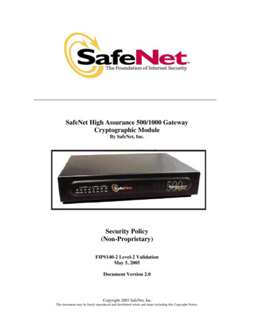
FPA-1000-UL Compact Fire PanelProduct Description en9Option -ISFLM-325-IWFLM-325-CZM4SLC 1SLC 2FPE-1000-SLCNAC12 V12 VD126 (7 Ah), D1218 (18 Ah),D1224 (24 Ah), D 1238 (38 Ah)FPE-1000-CITYBATB-40BATB-80Figure 2.1CITY TIEFPA-1000-UL System Architecture with OptionsBosch Security Systems, Inc.Installation and Operation GuideF.01U.075.420 2.0 2009.04
102.2en Product DescriptionFPA-1000-UL Compact Fire PanelFeaturesSystem Configuration–Basic configuration includes one analog addressable Signaling Line Circuit (SLC),configurable as two Class B Style 4 or one Class A Style 6 or 7––Second SLC easily expandable with FPE-1000-SLC Signaling Line CircuitUp to 127 detectors and modules, plus 127 analog sounder bases in combination with asuitable detector, for a total of 254 addressable device capacity per SLC, allowing for400 addresses or subaddresses per circuit–Uses standard wire; no shielded or twisted pair required on SLCs–Programmable sensitivity levels per device, and automatic day and night sensitivity–Automatic calibration and drift compensation routinemodes–120 V/240 V AC power, total 5.5 A transformer output–Two integrated NAC circuits rated at 2.5 A each, allowing up to 4 A total current (sharedbetween AUX power, Option Bus, and NAC)–Up to four addressable Remote Notification Appliance Circuit Power Supplies, providingAux power and up to 16 synchronized remote NAC circuits–Mainboard NAC patterns include Steady, Pulsing, Temporal Code 3, and Temporal–Built-in synchronization for appliances from Wheelock and System SensorCode 4, Wheelock and System Sensor–Three programmable Form C relays on the mainboard (fire, trouble, supervisory, gasalarm or activation by zone)–Option Bus for optional boards and expansions including LCD/LED annunciators, OctalDriver Module, Octal Relay Module, and Remote Notification Appliance Circuit PowerSupply–Optional City Tie Plug-in Module FPE-1000-CITY with two circuits, each programmable toLocal Energy or Reverse Polarity–Built-in Ethernet interface for Conettix IP reporting and/or programming and diagnostics–Built-in dual phone line PSTN/IP DACT communicator–Contact ID, SIA 300 and Modem IIIa2 reporting formats–UL Listed, FM/CSFM/MEA approvedEase of Use and Functionality–Large 4-line by 20-character LCD display–Six LED status indicators on each panel keypad or remote LCD annunciators, including–Menu-driven user interface on panel–Easy programming from panel keypad–Browser-based user interface for programming and diagnostics running on a networkedgas alarm LEDPC with Microsoft Windows XP and Microsoft Windows Vista or Unix/Linux basedoperating system, no software installation is required–Programmable authority levels, secured with a user-definable four-digit PIN–128 software zones for flexible input-output mapping–Auto Learn feature for easy start-up programming–Local piezo sounder–Fire drill test function–Walk test function–Alarm verification feature–Bypass or unbypass point, output or zone individuallyF.01U.075.420 2.0 2009.04Installation and Operation GuideBosch Security Systems, Inc.
FPA-1000-UL Compact Fire PanelProduct Description en11–1000 events history buffer–Event and history printing via network printer–Three language versions (English, Spanish, and Portuguese), software configurable, LEDand keypad labeling easy exchangeableHardware Features–Removable front door with keyed lock–Removable dead front door to access electronics–Mounting kit available for semi-flush installation with trim ring–Metal oxide varistors (MOVs) and spark gaps for protection from lightning surges andstatic dischargesBosch Security Systems, Inc.Installation and Operation GuideF.01U.075.420 2.0 2009.04
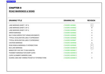
122.3en Product DescriptionFPA-1000-UL Compact Fire PanelSystem Overview Mainboard ComponentsSLCSLC 2SLC 1AUX Power OutAC INFire AlarmGas AlarmPowerSupervisorySilencedTroubleOption BusNAC 1DRILLRESETSILENCEACKNAC 2?@LINE 1PSTN. : ,A aCITY TIELocalEnergyLINE 2- BATT RELAY1RELAY2RELAY3ETHERNETM12 VFigure 2.2F.01U.075.420 2.0 2009.0412 VRelay 1 Relay 2 Relay 3ReversePolarityEthernetFPA-1000-UL MainboardInstallation and Operation GuideBosch Security Systems, Inc.
FPA-1000-UL Compact Fire PanelProduct Description enDesignationDescriptionKeypadWith LEDs, LCD display and keys.TransformerWorks with 120 V AC, 60 Hz or 240 V AC, 50 Hz.SLC 1 / SLC 2Signaling Line Circuit (SLC), standard configuration with one SLC,13second SLC with FPE-1000-SLC Plug-in Module,nominal 39 V DC (30 to 40 V DC), 200 mA maximum (per SLC), powerlimited, supervised.Option BusProvides serial data interface, with 500 mA at 12 V DC, power-limited,supervised.AUX :Two auxiliary power supply terminals, with 500 mA at 24 V DC each,FWR- FWR power-limited, non-supervised,RST- RST FWR Full Wave Rectified, non-switchedRST Resettable, switched and filtered.NAC 1 / NAC 2Terminal strips for two NACs, 2.5 A each.Wiring options Class A Style Z or Class B Style Y.See wiring example Figure 2.2 on page 12:–NAC 1: Class A Style Z–NAC 2: Class B Style YCITY TIESlot for City Tie Plug-in Module FPE-1000-CITY.RELAY 1Mainboard relays, default assignment is for alarm, trouble andRELAY 2supervisory; individually programmable for alarm, trouble, supervisory,RELAY 3gas alarm, activation by zone and system events,rated at 5 A, 30 V DC/10 A, 120 V AC.LINE 1 / LINE 2Phone line/IP connections through central station receiver (2 x RJ45).ETHERNETEthernet connection (RJ45).BATTTerminal strip for battery connection, 2 x 12 V, 18 Ah maximum withinenclosure or 40 Ah maximum external.Table 2.1Mainboard (MB) ComponentsThe boards, expanders and devices, listed in the following sections, are available from BoschSecurity Systems, Inc. to be used with the FPA-1000-UL Compact Fire Panel. For a completedescription of and installation instructions for each product, refer to the appropriate sectionof this manual and the documents supplied with the device.2.4Plug-in ModulesA second Signaling Line Circuit (SLC) can easily be added by plugging in the FPE-1000-SLC tothe mainboard.The City Tie Plug-in Module FPE-1000-CITY provides two circuits which can be programmed asLocal Energy or Reverse Polarity modType NumberDescriptionFPE-1000-SLCSignaling Line Circuit (second circuit or replacement)FPE-1000-CITYCity Tie Plug-in ModuleTable 2.2Bosch Security Systems, Inc.Plug-in ModulesInstallation and Operation GuideF.01U.075.420 2.0 2009.04
14en Product DescriptionFPA-1000-UL Compact Fire PanelCompatible Gamewell Devices for the City Tie Plug-in Module in Local Energy ModeDesignationDescriptionM34-56Local energy Trip, Surface Mount, Cottage ShellM34-110Same as M34-56 wth plain door painted blueM34-111Same as M34-56 wth plain door painted redM34-112Same as M34-56 wth plain door painted yellowM34-92Local energy Trip, Flush Mount, Gasketed cast frame for interior andexterior useM34-113Same as M34-92 wth plain door painted blueM34-114Same as M34-92 wth plain door painted redM34-75Local energy Trip, Surface Mount, Cottage Shell (less inner case testblock, tap key & bell)M34-115Same as M34-75 wth plain door painted blueM34-116Same as M34-75 wth plain door painted redM34-72Local energy Trip, Sheet Metal Housing (less inner case test block, tapkey & bell), Plain DoorTable 2.32.5Compatible Gamewell Devices for the City Tie Plug-in Module in Local Energy ModePower SupplyA transformer working with 120 V AC or 240 V AC is supplied standard with the control panel.Two backup batteries with 7 Ah or 18 Ah each fit inside the fire panel cabinet. A separatebattery box can provide higher capacity.The FPA-1000-UL provides two auxiliary power supplies with 0.5 A at 24 V DC each, with AUX/RST switchable. This auxiliary power can run expansion boards or other low current auxiliarydevices.Table 2.4 lists the available batteries and battery boxes. For selecting the necessary batterycapacity, refer to Section 3.1 Power Supply Calculations on page 21.Type NumberDescriptionD126Battery 12 V, 7 AhD1218Battery 12 V, 18 AhD1224Battery 12 V, 24 AhD1238Battery 12 V, 38 AhBATB-40Battery Box–Provides a single level (two-battery capacity) of battery storagewith an optional shelf that increases the battery capacity to fourbatteries.BATB-80Battery Box–Table 2.4Includes a mounted shelf that holds up to four batteries.Available Batteries and Battery BoxesFor installations requiring battery capacity higher than 40 Ah, a regulated and UL 1481 Listedexternal power supply can be used. The external power supplies connect through the panel'sbattery terminals. Batteries and battery charger are not supervised. For supervision of AC andbattery fault use an input module (for example FLM-325-2I4) on the SLC.F.01U.075.420 2.0 2009.04Installation and Operation GuideBosch Security Systems, Inc.
FPA-1000-UL Compact Fire Panel2.6Product Description en15Components Connected to the Option BusRemote Command Center and AnnunciatorsThe FPA-1000-UL supports–up to a total of eight FMR-1000-RCMD Remote Command Centers and/or FMR-1000-RARemote Annunciators–up to eight D7030X Series LED Annunciators with eight LED Zones each–up to eight D7030X Series/D7032 combinations.Type NumberDescriptionFMR-1000-RCMDRemote Command Center–Remote operational terminal of the FPA-1000-UL panel, providingbuttons for silence, reset, acknowledge, drill, scrolling keys, keyswitch with 1358 key, built-in piezo sounder.FMR-1000-RARemote Annunciator–Remote LCD annunciator, providing key for acknowledge andscrolling keys, built-in piezo sounder.D7030XLED Annunciator–Identifies the location of a fire alarm for up to eight zones allowedper system.D7030X-S2LED Annunciator–With two zones reserved for supervisory functions.–With power and trouble LEDs plus eight-zone LEDs that can beindividually labeled.D7030X-S8LED Annunciator–With eight zones reserved for supervisory functions.–With power and trouble LEDs plus eight-zone LEDs that can beindividually labeled.D7032Eight-Point LED Annunciator Expander–Attaches to a D7030X, D7030X-S2 or D7030X-S8.–Identifies the location of a fire alarm for eight additional zones,showing 16 LED zones in the D7030X/D7032 combination.D7031Remote Key Switch–Allows resetting the control panel and silencing the notificationappliances from the D7030X Series LED Annunciator's location.Table 2.5Controls and Annunciators for Connection to the Option BusFor requirements of Option Bus address restrictions, refer to Section 3.3.1 Option Bus AddressAssignment on page 34.For wiring requirements, refer to Section 4.9 Option Bus Wiring on page 58.ModulesThe FPA-1000-UL supports up to two Octal Relay Modules or Octal Driver Modules.The outputs are fully programmable, and can be activated by system events. These outputshave the same programming options as the local relays. Each output operates independentlyof the other seven to provide complete flexibility. Communication with the D7035/B orD7048/B is supervised.Bosch Security Systems, Inc.Installation and Operation GuideF.01U.075.420 2.0 2009.04
16en Product DescriptionFPA-1000-UL Compact Fire PanelType NumberDescriptionD7048/BOctal Driver ModuleD7035/BOctal Relay ModuleTable 2.6Modules for Connection to the Option BusFor wiring requirements, refer to Section 4.9 Option Bus Wiring on page 58.For requirements of address restrictions, refer to Section 3.3.1 Option Bus Address Assignmenton page 34.NAC Power SupplyThe FPP-RNAC-8A-4C Remote Notification Appliance Circuit Power Supply adds fouradditional Notification Appliance Circuits (NFPA 72, Class A Style Z or Class B Style Y) to thefire panel or serves as a power supply for fire protective signaling systems. This regulatedpower supply provides up to 8 A of power that is used to recharge batteries and operatecontinuous and intermittent alarm loads. This 8 A of power can be distributed through thefour NAC Power Supply circuits that are part of the FPP-RNAC-8A-4C. The FPP-RNAC-8A-4C isUL Listed for use in commercial fire alarm applications.Type NumberDescriptionFPP-RNAC-8A-4CRemote Notification Appliance Circuit Power SupplyTable 2.7NAC Power Supply Connected to the Option BusFor wiring requirements, refer to Section 4.9 Option Bus Wiring on page 58.2.7Signaling Line Circuit DevicesThe FPA-1000-UL Compact Fire Panel uses the patented Digital Communication Protocol(DCP) to communicate with each of the analog addressable devices located on the SLCs. Thisfast and reliable protocol allows the use of standard non-twisted, non-shielded wiring for theSLCs.The FPA-1000-UL supports two Class B, Style 4 or one Class A, Style 6 or 7 per SLC.Table 2.8 lists all compatible devices for the FPA-1000-UL SLCs:Type NumberDescriptionFAP-325Analog Photoelectric Smoke Detector[FAP325]–Detects optically dense smoke typical of fires involving materials suchas soft furnishings, plastic, foam or other similar materials which tendto smolder and produce large visible smoke particles.FAH-325Analog Heat Detector[FAH325]–Detects heat in environments where smoke detectors are unsuitablebecause of the presence of system or cooking fumes, such as in akitchen.FAI-325Analog Ionization Smoke Detector[FAI325]–For use in areas where early warning of trouble from superheated orflaming combustibles is expected; also constructed to be usedeffectively where outside Radio Frequency Interference (RFI) andother electrical interference is expected.FAA-325-B4Analog Detector Base–Compatible with all analog addressable detectors that use theadvanced analog communication protocol, except the FAD-325-DH.–F.01U.075.420 2.0 2009.044-in (10 cm) diameter.Installation and Operation GuideBosch Security Systems, Inc.
FPA-1000-UL Compact Fire PanelType NumberFAA-325-B6Product Description en17DescriptionAnalog Detector Base–Compatible with all analog addressable detectors that use theadvanced analog communication protocol, except the FAD-325-DH.–6-in (15 cm) diameter.FAA-325-B6SAnalog Sounder Base[FAA325-BS]–Contains an addressable sounder which provides an audible alarm inthe immediate vicinity.–Compatible with all analog addressable detectors that use theadvanced analog communication protocol, except the FAD-325-DH.–Auxiliary powered.–The FAA-325-B6S address is programmed automatically (for this, theaddress of the mounted detector plus 127 comes up to the sounderbase address).FAD-325-DHAnalog Duct Smoke Detector[FAD325]–Provides early detection of smoke and products of combustion presentin air moving through HVAC ducts in Commercial, Industrial andResidential applications.Three types available:–FAD-325-DH Analog Duct Smoke Detector Replacement Head–FAD-325 Analog Duct Smoke Detector (with Housing)–FAD-325-R Analog Duct Smoke Detector with Relay (with Housing)FMM-325A,Analog Manual StationsFMM-325A-D–Contact monitor module mounted in a corrosion-resistant rugged diecast housing for single-gang mounting.–Loop powered.Two types available:–FMM-325A Single-action Manual Station–FMM-325A-D Double-action Manual StationFLM-325-CZM4 Conventional Zone Module[FLM325-CZ]–Monitors dry contacts (NO) devices such as two-wire conventionaldetectors or pull stations.–Transmits the status of one zone of devices back to the panel(25 maximum per zone, number depends on type of connecteddevices).–Class A or Class B wiring is configured with a jumper on the modul–AUX powered.For compatible devices refer to the manual supplied with the product.The number of Conventional Zone Modules (FLM-325-CZM4) per SLCmodule is limited to 64.FLM-325-2I4Dual Input Monitor[FLM325-2I]–Provides two independent contact monitoring circuits while utilizing–Can be programmed to monitor normally open or normally closedonly one address on the SLC.contact fire alarm and supervisory devices (NO EOL, NC EOL,NC no EOL)–Bosch Security Systems, Inc.Supervises with Style B (Class B), loop powered.Installation and Operation GuideF.01U.075.420 2.0 2009.04
18en Product DescriptionFPA-1000-UL Compact Fire PanelType NumberDescriptionFLM-325-2R4Dual Relay Module[FLM325-2R]–Allows independent control of two Form C contacts (rated for 1.0 A at30 V DC or 0.5 A at 125 V DC) for a variety of normally open (NO) andnormally closed (NC) contact applications such as fan operation,elevator recall, door closure, and auxiliary notification.–D328ALoop powered.Analog Relay Module–Allows the control of one Form C contact (rated for 1.0 A at 30 V DC or0.5 A at 125 V DC) for a variety of normally open (NO) and normallyclosed (NC) contact applications such as elevator recall systems orHVAC shutdown.–FLM-325-ISOLoop powered.Short C
3.3.2 SLC Address Assignment 35 3.4 Telephone Requirements 35 . 5.4 Authority Level and PIN Codes 81 5.5 System Normal Display 83 5.6 Off-normal Display 84 5.7 Menu Navigation and Structure 87 . 2.0 2009.04 6.5 Overview of Graphical User Interface 127 6.6 Start Page 128 6.7 Programming 129 6.7.1 Site Data 130 6.7.2 SLC 1 and SLC 2 132