Transcription
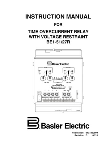
INSTRUCTION MANUALFORTIME OVERCURRENT RELAYWITH VOLTAGE RESTRAINTBE1-51/27RPublication: 9137200999Revision: D07/10
INTRODUCTIONThis instruction manual provides information about the operation and installation of the BE1-51/27R TimeOvercurrent Relay with Voltage Restraint. To accomplish this, the following information is provided: General Information and Specifications Controls and Indicators Functional Description Installation Tests and AdjustmentsWARNING!To avoid personal injury or equipment damage, only qualified personnel shouldperform the procedures in this manual.NOTEBe sure that the BE1-51/27R is hard-wired to earth ground with no smaller than12 AWG copper wire attached to the ground terminal on the rear of the unit case.When the BE1-51/27R is configured in a system with other devices, it isrecommended to use a separate lead to the ground bus from each unit.9137200999 Rev DBE1-51/27R Introductioni
First Printing: September 1993Printed in USACopyright 1993-2010 Basler Electric, Highland Illinois 62249 USAAll Rights ReservedJuly 2010CONFIDENTIAL INFORMATIONof Basler Electric, Highland Illinois, USA. It is loaned for confidential use, subjectto return on request, and with the mutual understanding that it will not be used inany manner detrimental to the interest of Basler Electric.It is not the intention of this manual to cover all details and variations in equipment, nor does this manualprovide data for every possible contingency regarding installation or operation. The availability and designof all features and options are subject to modification without notice. Should further information berequired, contact Basler Electric.BASLER ELECTRICROUTE 143, BOX 269HIGHLAND IL 62249 USAhttp://www.basler.com, info@basler.comPHONE 1 618.654.2341FAX 1 618.654.2351iiBE1-51/27R Introduction9137200999 Rev D
REVISION HISTORYThe following information provides a historical summary of the changes made to the BE1-51/27Rinstruction manual (9137200999). Revisions are listed in reverse chronological order.ManualRevision and DateChangeD, 07/10 Replaced cover drawing and Figure 2-1. (New front panel switchesand graphics.)C, 08/07 Moved content of Section 6, Maintenance to Section 4.Move Time Curve Graphs from Section 1 to Appendix A.Updated front panel illustrations to show laser graphics.Added manual part number and revision to all footers.Updated manual to current style used.Updated power supply burden data in Section 1.Updated Target Indicator description in Section 3.B, 05/05 Added new information on wide range power supplies.Added new information on case covers.Changed Specifications, Accuracy, Page 1-10 and Isolation, Page 111.Corrected Figure 1-51 and Table 2-4.Deleted Figures 4-8 and 4-9, and references to the Service Manual(obsolete) in the Introduction and Section 6. A, 09/03 Enhanced the description of the B and C curves in Section 1.Changes Specifications: Time Overcurrent Pickup Accuracy; TimeOvercurrent Dropout Ratio, and Isolation.Added formula for pickup current and Chart 1-1, InstantaneousResponse Time.Corrected Table 1-3, Figure 1-49, and Tables 2-2 and 2-4.Corrected Figures 5-1 through 5-6 and Test Procedures to reflectchanges in the Specifications.Added Section 7, Changes. Initial release —, 09/939137200999 Rev DBE1-51/27R Introductioniii
This page intentionally left blank.ivBE1-51/27R Introduction9137200999 Rev D
CONTENTSSECTION 1 GENERAL INFORMATION . 1-1SECTION 2 CONTROLS AND INDICATORS . 2-1SECTION 3 FUNCTIONAL DESCRIPTION . 3-1SECTION 4 INSTALLATION . 4-1SECTION 5 TESTS AND ADJUSTMENTS . 5-1APPENDIX A TIME OVERCURRENT CHARACTERISTIC CURVES . A-19137200999 Rev DBE1-51/27R Introductionv
This page intentionally left blank.viBE1-51/27R Introduction9137200999 Rev D
SECTION 1 GENERAL INFORMATIONTABLE OF CONTENTSSECTION 1 GENERAL INFORMATION . 1-1DESCRIPTION. 1-1APPLICATION . 1-1Backup Protection . 1-1Residually Connected . 1-1Operating Characteristics at Reduced Voltages . 1-2STANDARD FEATURES . 1-3Time Overcurrent Functions . 1-3Non-Integrating Timing . 1-4Integrating Timing . 1-5Built-In Test . 1-5OPTIONS . 1-5Timing . 1-5Sensing Input Type . 1-5Sensing Input Range . 1-5Power Supply . 1-5Targets . 1-6Outputs . 1-6Instantaneous Outputs . 1-6Packaging . 1-6MODEL AND STYLE NUMBER DESCRIPTION . 1-6SPECIFICATIONS . 1-7Voltage Sensing Inputs . 1-8Sensing Input Burden . 1-8Sensing Input Rating . 1-8Time Overcurrent Pickup Selection Range . 1-8Time Overcurrent Pickup Accuracy . 1-8Time Overcurrent Dropout Ratio . 1-8Instantaneous Overcurrent Pickup Range . 1-8Instantaneous Overcurrent Measuring Accuracy . 1-8Instantaneous Overcurrent Dropout Ratio . 1-8Instantaneous Response. 1-8Time Delay Accuracy . 1-9Output Circuits . 1-9Target Indicators . 1-9Power Supply . 1-9Radio Frequency Interference (RFI) . 1-10Isolation . 1-10Surge Withstand Capability . 1-10UL Recognized . 1-10GOST-R. 1-10Operating Temperature . 1-10Storage Temperature . 1-10Shock. 1-10Vibration . 1-10Weight . 1-10Case Size . 1-10FiguresFigure 1-1. Style Number Identification Chart . 1-7Figure 1-2. Typical Instantaneous Response Time . 1-99137200999 Rev DBE1-51/27R General Informationi
TablesTable 1-1. Timing, Characteristic Curve B4, with BE1-51/27R at 100% and 50% Voltages . 1-2Table 1-2. Timing, Curve B4, BE1-51/27R at 25% Voltage (00 to 10 Time Dial Settings) . 1-2Table 1-3. Timing, Curve B4, BE1-51/27R at 25% Voltage (20 to 99 Time Dial Settings) . 1-3Table 1-4. Power Supply Specifications . 1-9iiBE1-51/27R General Information9137200999 Rev D
SECTION 1 GENERAL INFORMATIONDESCRIPTIONBE1-51/27R Time Overcurrent Relays are microprocessor-based devices that provide voltage restraint ofthe phase time overcurrent function. With voltage restraint, the current pickup decreases proportionatelywith decreasing voltage over the rated voltage range. Instantaneous overcurrent element(s) and theneutral time overcurrent element, when supplied, operate independently of the voltage restraint function.Each relay is available with one, three, or four time overcurrent elements.APPLICATIONVoltage restraint provides an added means of discriminating between load and fault conditions. Thisallows the time overcurrent pickup to be set below the maximum load (or swing) current. This featurepermits the relay to provide dual protection on a generator. For example, either backing up the differentialprotection for generator faults and/or backing up other relays external to the generator zone. As a backup function, it must be set with a relatively long delay. Prior to relay time-out, the synchronous impedanceof the generator may be limiting fault current to a level comparable to rated. If the regulator is not inservice to boost excitation, the steady-state fault current, even for a fault on the machine terminals, willusually be less than rated. The relay pickup must be below generator rated current to insure dependableoperation.Backup ProtectionThis relay is useful for generator time overcurrent back-up protection for other relaying external to thesystem. It also provides primary (first line) phase fault protection for small generators not equipped withdifferential protection.Phase overcurrent units should be supplied on all three phases. Either three single-phase relays or onethree-phase relay when the objective is to protect for phase-phase faults on the other side of a delta-wyepower transformer. Currents at the relay for a three-phase fault are in the proportions of 2:1:1 in the threephases, so only one phase sees the higher current level. For this application, each phase timeovercurrent element should be restrained by the phase-to-ground voltage on its phase, rather than by thephase-phase voltage.Following fault inception, current varies continuously as the field current decays. In addition, for other thana bolted fault on the terminals of a generator, the voltage will not be zero and will vary with time as thefault current decays. If the restraint voltage is between 25 and 100 percent, the time overcurrent elementpickup will also vary with the time because of the changing voltage. Because the pickup varies with time,the multiples of pickup, and therefore the timing, will also change. These factors must be consideredwhen coordinating with external protective devices. Section 4 of this manual provides additionalcoordination information in the paragraphs on setting the relay.Instantaneous overcurrent elements would not ordinarily be used for a generator back-up function. Theywould not have acceptable operation for faults external to the generator zone.Because the phase time-overcurrent pickup will be less than the maximum non-fault current, the relay canmisoperate if the voltage signal is interrupted (e.g., a blown voltage transformer fuse). Where two sourcesof signal voltage are available, the BE1-60 Voltage Balance relay can prevent such a misoperation. Thisrelay compares the output of two signal sources to detect an anomaly in one of these sources and blockthe operation of those devices connected to that signal source.Residually ConnectedA neutral (ground) overcurrent element can be applied and connected residually to a set of three currenttransformers on solidly grounded applications or on impedance grounded systems that provide groundfault current approximating rated current level. The neutral element can also be connected to a 10/1ampere, zero-sequence window current transformer to provide protection on systems producing aminimum of about 20 amperes primary current. Still another alternative would be connecting this device toa current transformer in the neutral of a generator.9137200999 Rev DBE1-51/27R General Information1-1
Operating Characteristics at Reduced VoltagesBE1-51/27R relays adjust the operating parameters based on system voltage. The sensitivity of the relayis increased as the system voltage drops. This provides a means of discriminating between load and faultconditions.A decrease of the sensed voltage to a point between 100 percent and 25 percent of nominal results in aproportional decrease in the time overcurrent pickup point. Thus, at 50 percent nominal voltage, the timeovercurrent relay will pickup at 50 percent of the setting (TAP Calibration). At voltages above 100percent nominal, the pickup will be the same as the setting. At voltages below 25 percent of nominal, thepickup will be 25 percent of the setting. Note that the BE1-51/27R is designed to trip at currents less thanthe setting if the voltage is depressed.The timing characteristics of the BE1-51/27R continue to operate on multiples of pickup basis. Pickuprefers not to the setting, but to the operating point as adjusted for voltage. Thus, with a setting of 5.0amperes, and system voltage of 50 percent, a current of 5.0 amperes represents 2 times pickup. For agiven fault current magnitude, the relay will trip faster at reduced voltage, because the multiples of pickupincreases.Table 1-1 shows the timing characteristics at normal and reduced voltages. The curve is B4 and the timedial is five. The pickup is five amperes. Tables 1-2 and 1-3 show the timing characteristics for multiples ofsetting as it relates to multiples of pickup with the BE1-51/27R at 25 percent voltage.Table 1-1. Timing, Characteristic Curve B4, with BE1-51/27R at 100% and 50% ltiples ofPickupApproximate TripTime4.25 A100%5.0 A 1.0No Trip4.25 A50%2.5 A1.71.499 s4.25 A0%1.25 A3.40.507 s7.50 A100%5.0 A1.51.873 s7.50 A50%2.5 A3.00.772 s7.50 A0%1.25 A6.00.474 s15.00 A100%5.0 A3.00.772 s15.00 A50%2.5 A6.00.474 s15.00 A0%1.25 A12.00.355 sTable 1-2. Timing, Curve B4, BE1-51/27R at 25% Voltage (00 to 10 Time Dial Settings)Time Dial Setting (Seconds)Multiple ofSettingMultiple R General Information9137200999 Rev D
Time Dial Setting (Seconds)Multiple ofSettingMultiple 0.3160.4000.526Table 1-3. Timing, Curve B4, BE1-51/27R at 25% Voltage (20 to 99 Time Dial Settings)Time Dial Setting (Seconds)Multiple ofSettingMultiple ANDARD FEATURESTime Overcurrent FunctionsTime overcurrent elements pick up over a range of 0.1 to 0.8 amperes, 0.3 to 2.4 amperes, 0.5 to 4.0amperes, 1.5 to 12.0 amperes, 0.1 to 2.4 amperes, or 0.5 to 12.0 amperes and provide an adjustable timedelay that is proportional to the overcurrent. Time delay is initiated when the sensed current exceeds thepickup point. When the current drops below the pickup point, the timing circuit is reset immediately. Atreset, the output contacts, if operated, are restored to normal.9137200999 Rev DBE1-51/27R General Information1-3
Adjustment of the overcurrent pickup point is provided by controls on the relay front panel. Time delay is afunction of the characteristic curve that has been selected. Time delay is settable from 00 to 99 on theTIME DIAL thumbwheel switch located on the front panel. Curve type is selected either as an option or, insome models, is switch selectable.Sixty-nine characteristic curves and three timing options are available. They are:Characteristic curves: Seven inverse time2Nine I tSeven inverse time with extended timing range2Nine I t with extended timing rangeFive British Standard 142 (E curves)Seven integrating inverse time2Nine integrating I tSeven integrating inverse time with extended timing range2Nine integrating I t with extended timing rangeTiming option Z1 (switch selectable - 16 position) B and C curves: Seven inverse time2 Nine I tTiming option Z1 with option 2-D or 2-E (switch selectable - 16 position) B and C curves: Seven inverse time with extended timing range2 Nine I t with extended timing rangeTiming option Z2 (switch selectable - 16 position) B and E (British Standard 142) curves: Seven inverse time2 One I t Five British Standard (BS) 142 (E curves)Timing option Z2 with option 2-D or 2-E (switch selectable - 16 position) B and E (BS142) curves: Seven inverse time with extended timing range2 One I t with extended timing range Five British Standard 142 (E curves)Timing option Z3 (switch selectable - 16 position) integrating B and C curves: Seven integrating inverse time2 Nine integrating I tTiming option Z3 with option 2-D or 2-E (switch selectable - 16 position) integrating extended B and Ccurves: Seven integrating inverse time with extended timing range2 Nine integrating I t with extended timing rangeCharacteristic curves are shown by the graphs in Appendix A, Time Overcurrent Characteristic Curves.Note that each graph (i.e. function) consists of a set of representative curves. Each curve (as well as anybetween-curve interpolation) is selectable by the front panel TIME DIAL using a two-digit destination from00 to 99. Because of space limitations, each graph shows only 14 of the 100 possible selections.Non-Integrating TimingTiming options Z1 and Z2 and the characteristic curves available with those options use non-integratingtiming. Non-integrating timing is accomplished by timing at a gate that is not solely dependent on themagnitude of the applied multiple of pickup current. The time-out value is calculated based on the type oftime curve characteristic selected, time dial setting, and the magnitude of the applied multiple of pickupcurrent. The time-out value is continuously updated during the timing cycle. When pickup is exceeded, atimer is initiated. When the timer elapsed time exceeds the calculated time-out value, a time trip outputsignal is generated.This type of non-integrating time delay characteristic exhibits a dynamic characteristic that is immediatelyresponsive to changes of the applied multiple of pickup current.1-4BE1-51/27R General Information9137200999 Rev D
Integrating TimingTiming option Z3 and the characteristic curves available for that option uses integrating timing. Integratingtiming is accomplished by summing time increments that are based on the magnitude of the appliedmultiple of pickup current, the time curve characteristic selected, and the time dial value. These timeincrements are summed until a predetermined value is exceeded, then a time trip output signal isgenerated.This type of integrating time delay characteristic simulates the operating characteristics of anelectromechanical overcurrent relay.Built-In TestA built-in test (BIT) switch mounted on the Logic Board provides diagnostic troubleshooting andcalibration.OPTIONSTimingAn extended timing option multiplies by approximately 5.7, the standard time delays. The resulting curvesare shown following the standard curves in Appendix A - e.g., Figure A-1 is timing type B1 and Figure A-2is the timing type B1 with extended timing range.When timing option Z1, Z2, or Z3 is specified, a printed circuit board mounted selector switch allows achoice of up to sixteen different time overcurrent functions. Timing option Z1 or Z3 may be furtherspecified as standard or extended time, depending upon option 2 selection.Sensing Input TypeWhen single-phase, two-phase-and-neutral, three-phase, or three-phase-and-neutral sensing has beenspecified, the front panel TAP selector and the front panel TAP CAL control set the pickup point for allphases. An independent front panel TAP (NEUTRAL) selector and front panel CAL (NEUTRAL) controlset the neutral pickup point. In addition, for three-phase-and-neutral sensing units, one of the sevensensing input range combinations must be specified.Relay circuits provide a voltage restraint circuit that varies the selected time overcurrent pickup pointproportional to the monitored voltage. As the monitored voltage varies between 100 percent and 25percent of nominal, the pickup point for each phase varies between 100 percent and 25 percent. Nominalvoltage is 100 Vac for 50-hertz systems and 120 Vac for 60-hertz systems. Neutral time overcurrentelements are not restrained. Three-phase voltages are measured phase-to-phase for three wireconnections and phase-to-neutral for four wire connections.Sensing Input RangeFor three-phase-and-neutral sensing units, input ranges are: 0.5 to 4.0 amperes (phase and neutral)1.5 to 12 amperes (phase) and 0.5 to 4.0 amperes (neutral)0.5 to 4 amperes (phase) and 1.5 to 12 amperes (neutral)1.5 to 12 amperes (phase and neutral)0.1 to 0.8 amperes (phase and neutral)0.3 to 2.4 amperes (phase) and 0.1 to 0.8 amperes (neutral)0.3 to 2.4 amperes (phase and neutral)For all other units, two ranges are available. They are 0.5 to 12 amperes and 0.1 to 2.4 amperes.Power SupplyFive power supply options are available. They are: 24 Vdc48 Vdc125 Vdc and 100/125 Vac48 Vdc or 125 Vdc and 100/125 Vac250 Vdc and 240 Vac9137200999 Rev DBE1-51/27R General Information1-5
TargetsSingle-phase relays have two function targets that indicate when the time delay or instantaneouselement(s) have operated. On multiple phase relays, additional targets indicate which phase or neutralelement(s) operated.Function targets may be specified as either internally operated or current operated by a minimum of 0.2amperes through the output trip circuit. When current operated, the output circuit must be limited to 30amperes for 0.2 seconds, 7 amperes for 2 minutes, and 3 amperes continuously.OutputsOptional normally opened, normally closed, or SPDT auxiliary output contacts may be selected. Contactsactuate when the output relay is energized. Internally operated front panel mounted targets, and frontpanel targets operated by the dc current in the output circuit are available for the time overcurrent andinstantaneous overcurrent functions. Optional front panel mounted PUSH-TO-ENERGIZE-OUTPUTpushbuttons allow direct actuation of each output relay for external circuit testing.Instantaneous OutputsOne or two instantaneous overcurrent outputs are optionally available. Each is adjustable up to 40 timesthe time overcurrent pickup point. When the sensed current exceeds the instantaneous overcurrentpickup point, an output relay is energized. An independent front panel control (INST 1 or INST 2) adjuststhe pickup point for each optional output. If more than one phase is applied to the relay, the instantaneouspickup point will be the same for all phases. If neutral current is sensed, a front panel INST 1 (NEUTRAL)provides adjustment of the neutral pickup point. Instantaneous overcurrent elements are not voltagecontrolled.PackagingEach relay is mounted in a drawout cradle and enclosed in a standard utility style case with either semiflush or projection mounting (depending upon case style selected). An available test plug (Basler Electricpart number 10095) allows the relay to be tested in place without disturbing external control circuit wiring.MODEL AND STYLE NUMBER DESCRIPTIONBE1-51/27R Time Overcurrent Relay electrical characteristics and operational features are defined by acombination of letters and numbers that make up its style number. The model number, together with thestyle number, describes the options included in a specific device, and appears on the front panel, drawoutcradle, and inside the case assembly. Upon receipt of a relay, be sure to check the style number againstthe requisition and the packing list to ensure that they agree.Style Number Identification Chart (Figure 1-1) illustrates the manner in which the relay style number isdetermined. For example, if the style number were U3E-Z1P-B1C1F, the device would have the e-and-Neutral sensing, 3-phase, 4-wire voltage restraintSensing input range of 1.5 to 12.0 amperes for phase and 0.5 to 4.0 amperes for neutralNormally open outputsSwitch selectable time curvesOperating po
three-phase relay when the objective is to protect for phasephase faults on the other side of a delta- wye - power transformer. Currents at the relay for a threephase fault are in the proportions of 2:1:1 in the three - phases, so only one phase sees the higher current level. For this application, each phase time-


