Transcription
LM.com-liMnBE1-59NGROUND FAULTtManualsOVERVOLTAGE RELAYarThe BE1-59N Ground Fault Overvoltage Relay provides sensitive protection forungrounded and high resistance grounded systems.lPADVANTAGES Provides 100% stator ground fault protection.100/120 Vac or 200/240 Vac nominal sensing input.Four sensitivity ranges for overvoltage are available: 1-20 and 10-50 Vac for a Four sensitivity ranges for undervoltage are available: 0.1-2.5 Vac and 0.5-12 Vacca 100/120 Vac input and 2-40 and 20-100 Vac for a 200/240 Vac input.for a 100/120 Vac input and 0.2-5 Vac and 1-24 Vac for a 200/240 Vac input.Instantaneous, definite, and inverse time characteristics. 40 dB harmonic filtering. Low sensing input burden. Power supply status contact.SPECIFICATIONSPage 3lec APPLICATION·Page2tri Qualified to the requirements of-ANSI/IEEE C37.90. 1-1989 and IEC 255 for surge withstand capability;EXTERNALCONNECTIONSPage 6- IEC 255-5 for impulse.UL Recognized under Standard 508, UL File #E97033.E rORDERINGPage 7ADDITIONAL INFORMATIONINSTRUCTION MANUAlwRequest publication 9-1714-00-990STANDARDS, DIMENSIONS & ACCESSORIESwwRequest bulletin SDA§l Basler ElectricP. 0. BOX 269 HIGHLAND, ILLINOIS 62249, U.S.A.PHONE 618·654·2341FAX 618·654·2351UBG-610-95
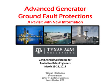
.comBE1-59N GROUND FAULT OVERVOLTAGE ----APPLICATIONThe BE1-59N ground fault overvoltage relay monitorsthe fundamental frequency (50 or 60 Hz) voltagewhich accompanies a ground fault, and is insensitiveto the third harmonic voltage present during normaloperation.One hundred percent protection of the generatorstator windings is obtainable with the optional over lapping undervoltage element. The undervoltageelement is tuned to measure the third harmonic voltagewhich is present in the generator neutral under normaloperating conditions. The under voltage elementdetects the reduction of the normal third harmonicvoltage which accompanies a ground fault near theneutral point of the generator.tMBut it remains important to detect and isolate single phase-to-ground faults in order to prevent theirevolution into more dangerous faults such as phase to-phase-to-ground and three-phase-to-ground faults.Sensitive voltage relays can be used to detect groundfaults where the fault current is very small. TheBE1-59N is especially suited to the task.ualsThe available fault current for single-phase-to-groundfaults is very limited for ungrounded systems andsystems which are grounded through a high resistance.This current limiting reduces the possibility of exten sive equipment damage, and eliminates the need fora neutral breaker by reducing the fault current belowthe level required to sustain an arc.point must be higher than any neutral voltage resultingfrom normal unbalances in order to avoid nuisancetrips. This will allow a certain percentage of the statorwindings near the neutral to go unprotected by theovervoltage relay. The overvoltage relay functiontypically protects 90 to 95 % of the generator statorwindings.anPURPOSEHIGH RESISTANCE GROUNDINGRp calParA common method of grounding an ac generator is toconnect a distribution transformer between the neutralof the generator and the station ground. The distribu tion transformer's primary voltage rating is equal to, orgreater than, the generator's rated line-to-neutral volt age. Its secondary is rated at 200/240 Vac or 100/120Vac. A resistor is connected across the secondarywinding of the transformer. When reflected through thetransformer it is effectively a high resistance.R s X N2lectriwhere RP is the effective primary resistanceR5 is the actual value of the secondaryresistorN is the turns ratio of the distributiontransformer.EThe available single-phase-to-ground fault current atthe generator terminals is greatly reduced by the higheffective resistance of the distribution transformer andsecondary resistor. The distribution transformer pro vides isolation for the protection scheme and reducesthe voltage to a convenient level.UNGROUNDED SYSTEMSThe BE1-59N ground fault overvoltage relay is usedto detect ground faults on ungrounded three-phase three-wire systems. The relay is connected as shownin Figure 1. A set of voltage transformers are wiredwith a grounded wye primary and a broken deltasecondary. The BE1-59N is connected across thebroken delta. It is often necessary to connect a resistoracross the broken delta to avoid ferroresonance.SOURCEwwwThe BE 1-59N ground fault overvoltage relay is con nected across the secondary resistor to detect theincrease in voltage across the distribution transformercaused by a ground fault in the generator stator wind ings. A ground fault at the generator terminals willresult in rated line-to-neutral voltage across the trans former primary, while ground faults near the neutralwill result in lower voltages. The overvoltage relay set-An undervoltage inhibit feature is included with thethird harmonic undervoltage element. This featuresupervises the undervoltage element of the groundfault relay to prevent misoperation during startup andshutdown by monitoring the generator terminal voltage.259NFIGURE 1. UNGROUNDED 3-PHASE, 3-WIRE SYSTEM
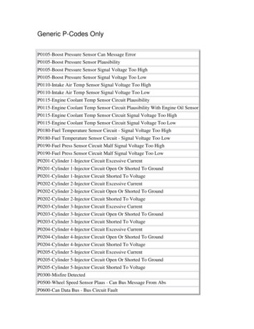
APPLICATIONThe grounded wye/broken delta voltage transformersact as a zero sequence filter by summing the threephase voltages. Under normal conditions this sum iszero. When a ground fault occurs, the BE1-59N groundfault overvoltage relay will detect the presence of thesecondary zero sequence voltage (3V0}.BE1-59N GROUND FAULT OVERVOLTAGE.com------(continued)The BE1-59N ground fault overvoltage relay greatlyreduces the risk of equipment damage by detectingand isolating the first ground to occur on an un grounded system.The specifications on these pages define the featuresand options that can be combined to exactly satisfyan application requirement. The block diagram (Figure2) illustrates how the various standard features, as wellas the options, function together.filter to obtain the fundamental component of the inputvoltage. If this voltage exceeds the OVERVOLTAGEPICKUP (controlled at the front panel}, an LED illu minates, and an internal signal is developed which maybe employed three different ways, depending upon thetiming option selected.anFUNCTIONAL DESCRIPTIONualsSPECIFICATIONS1. The overvoltage output relay is energized instan taneously.INPUTS2. A definite time delay is initiated whose period isdetermined by the front panel TIME DIAL over arange or 0.1 to 99.9 seconds. At the expiration of thetime delay, the overvoltage output contacts close.tMNominal sensing input ratings, defined by the stylenumber, are 100/120 or 200/240 Vac with a maximumburden of 2 VA single-phase at nominal 50/60 Hz. Themaximum continuous voltage rating is 360 Vac for100/120 Vac nominal, and 480 Vac for 200/240 Vacnominal.ar3. An inverse time delay is initiated whose period isdetermined by two factors:Overvoltage SensingcalPIn a typical application, the BE1-59N Ground FaultOvervoltage Relay monitors the voltage across a re sistor in the generator's grounding circuit. The voltageacross the resistor is supplied to the sensing trans former in the relay.b. Selection of a particular response curve by thefront panel Tl ME DELAY over the range of 01 to99 ( 5% or 25 mSec, whichever is greater)(Reference Figure 4.)www.ElectriThe derived secondary voltage is applied to an activea. Magnitude of the overvoltage condition ( 2% or100 mV or whichever is greater for the 120 Vacpickup range or 2% or 200 mV for the 240 Vacpickup range}, andUNDERVOLTAGEDEFINITEOR INVERSETIME DELAYFRONT PANELEXTERNALPOWER -1------1SOURCEFIGURE 2. FUNCTIONAL BLOCK D I AGRAM3
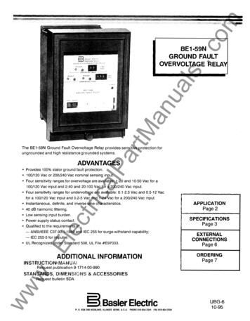
SPECIFICATIONS.comBE1-59N GROUND FAULT OVERVOLTAGE ----(continued)Undervoltage InhibitAn optional undervoltage measuring element is sensi tive to the third harmonic (150 Hz or 180 Hz) voltagepresent at the generator neutral, and insensitive to thefundamental frequency (50 or 60 Hz). The under voltage element determines within 5 cycles whetherthe third harmonic voltage is above or below theUNDERVOLTAGE PICKUP setting on the front panel.If below, the UNDERVOLTAGE LED will illuminate, andan internal signal is developed which may be employedthree different ways, depending upon the timing optionselected.When the undervoltage sensing option is selected, anundervoltage inhibit circuit is included which monitorsthe generator terminal voltage. When the terminalvoltage is less than the UNDERVOLTAGE INHIBITsetting on the front panel, the undervoltage sensingoption is inhibited to prevent relay operation duringstart-up or shutdown of the generating unit.ualsUndervoltage Sensing OptionThe UNDERVOLTAGE INHIBIT range is continuouslyadjustable from 40 to 120 Vac for the nominal 100/120Vac units, and 80 to 240 Vac for the 200/240 Vac units.PICKUP ACCURACY2. A definite time delay is initiated whose period isdetermined by the front panel T IME DIAL over arange or 0.1 to 99.9 seconds. At the expiration of thetime delay, the undervoltage output contacts close.Relay pickup will not vary from its setting more than asfollows for variations in input power or operatingtemperature within the specified limits.For 120 Vac sensing range: 2.0% or 100 millivolts,whichever is greater.For 240 Vac sensing range: 2.0% or 200 millivolts,whichever is greater.ara. Magnitude of the undervoltage condition ( 2% or100 mV or whichever is greater for the 120 Vacpickup range or 2% or 200 mV for the 240 Vacpickup range), andtM3. An inverse time delay is initiated whose period isdetermined by two factors:an1. The undervoltage output relay is energized instan taneously.DROPOUT RATIOcalPb. Selection of a particular response curve by thefront panel T IME D IAL over the range of 01 to99 ( 5% or 25 mSec, whichever is greater)(Reference Figure 3.)40.0.Electri30.0··--- 0"4.03.03.02.02.00w " 4070.3030.20220100703w 6.05.00.705§704.0: :-- ::::.40Overvoltage and undervoltage elements reset within2.0% of their actual pickup level within seven cycles.0502010.1121110987654321 100/120Vac 8161412108642 200/240 Vac INPUT200/240Vac INPUT2468101214161820222426283032ww403020.1VOLTAGE DIFFERENCE FROM PICKUPVOLTAGE DIFFERENCE FROM PICKUPFIGURE 3. UNDERVOLTAGE INVERSE TIMEFIGURE 4. OVERVOLTAGE INVERSE TIMECHARACTERISTIC CURVESCHAR ACTERISTIC CURVES
SPECIFICATIONSBE1-59N GROUND FAULTOVERVOLTAGEccontinued).com-------TIMING ACCURACYInductiveDefinite time is adjustable from 00.1 to 99. 9 seconds,in steps of 0.1 seconds. Accuracy is within % ofleast significant digit 25.0 milliseconds.120/240 Vac, 125 Vdc, 250 Vdc - break 0.1 A(L/R 0.04).KJLNominalVoltage48 Vdc125 Vdc24 VdcBurden?.OW120 Vac7.5WzY*48 Vdc250 Vdc125 Vdc230 Vac7.5W15.0 VA?.OW7.5WarTypetMTABLE 1. POWER SUPPLY OPTIONS12.0W33.5 VA48or125lPpower supply is field selectable for use with eitherVdc. Selection must be accomplished at the time of installation and prior tothe application of power.caPOWER SUPPLY STATUS OUTPUTlectriThe power supply output relay is energized and itsNC output contact is opened when power is appliedto the relay. Normal internal relay operating voltagemaintains the power supply status output relay in acontinuously energized state with its output contactopen. If the power supply output voltage falls below therequirements of proper operation, the power supplyoutput relay is deenergized, closing the NC outputcontact.OUTPUTS.EOutput contacts are rated as follows:Resistivew120/240 Vac - make 30 A for 0.2 seconds, carry7 A continuously, break 7 A.250 Vdc - make and carry 30 A for 0.2 seconds, carry7 A continuously, break 0.1 A.wwMagnetically latched, manually reset, target indicatorsare optionally available to indicate that an output hastripped. Either internally operated or current operatedtargets may be specified. Current operated targetsrequire 0.2 A in the output trip circuit to actuate, andtrip circuit current must not exceed 30 A for 0.2seconds, 7 A for 2 minutes, and 3 A continuous.Current operated targets may be selected only whennormally open (NO) output contacts have beenspecified.anOne of five power supply types may be selected toprovide internal operating power. They are describedin Table 1.YAccessible with a thin non-conducting rod through thefront panel, push-to-energize pushbuttons are availableto energize each output relay for testing the externalcontrol/protective system wiring.TARGETPOWER SUPPLY*The typePush-to-Energize Output PushbuttonsualsInverse time is adjustable from 01 to 99 in incrementsof 01. The setting defines a curve as illustrated inFigures 3 and 4. Inverse timing is accurate within 5%or 25.0 milliseconds, whichever is greater, for anycombination of time dial and pickup setting.500 Vdc - make and carry 15 A for 0.2 seconds, carry7 A continuously, break 0.1 A.SURGE WITHSTAND CAPABILITYQualified to ANSI/IEEE C37. 90-1978, C37.90a-1974,Surge Withstand Capability Test and IEC 255, ImpulseTest and Dielectric Test.MECHANICALOperating Temperature-40 C (-40 F) to 70 C ( 158 F)Storage Temperature-65 C (-85 F) to 100 C ( 212 F)Case Size: S 1.W eight13.6 pounds maximum.ShockIn standard tests, the relay has withstood 15g in eachof three mutually perpendicular axes without structuraldamage or degradation of performance.VibrationIn standard tests, the relay has withstood 2g in eachof three mutually perpendicular axes swept over therange of 10 to 500 Hz for a total of six sweeps, 15minutes for each sweep, without structural damage ordegradation of performance.5
.comBE1-59N GROUND FAULT OVERVOLTAGE ------CONNECTIONSCONTROL;·BUS).\r'59NII39&I,.L ./'59N \1 OWf ER}59N12PS.I59NQ4 )59N1352/,r' "V""'BUSBACB92059N18 59N19GROUND FAULT OVERVOLTAGE RELAYPOWER CIRCUIT BREAKERFUSETRIP COILOVOVER VOLTAGE CONTACTSUVOPTI ONAL UNDER VOLT AGE CONTACTSPSPOWER SUPPLY STATU S caA59NTC.&lP- CONTROLn59N59N1T59N20an IIILEGEND:ar528,& &59NtM'559N8:&IIrT59Nuals N.O. CONTACTS SH OWN. ALSO AVAILABLEWITH N.C. CONTACTS. TARGET AVAILABLEWITH N.O. CONTACTS ONLY.DASHED LINES APPLY ONLY TO D.C.POWERED MODELS.OPTI ONAL A U X I L I A R Y OVER VOL TAGE R E L A YA V A IL A B LE WI T H N.O. O R N . C . CONTACTS.OPTIONAL AUXILIARY UNDERVOLTAGE RELAYAVAILABLE WITH N.O. OR N.C. D FAULT OVERVOLTAGE6RBE1-59N59N7BE1-59NOVERLAPPING GROUND FAULT(UNDERVOLTAGE AND OVERVOLTAGE)FIGURE 5. TYPICAL CONNECTIONSUNGROUNDED SYSTEM
.com------- BE1-59N GROUND FAULT OVERVOLTAGEORDERINGMODEL NUMBEROutput(F)Timing(F6) Inverse for the overvoltagefunction; definite time forthe undervoltage functionTwo NO output relays: onefor the overvoltage functionand one for the undervoltagefunctionThe style number appears on the front panel, drawoutcradle, and inside the case assembly. This style num ber is an alphanumeric combination of charactersidentifying the features included in a particular unit.The sample style number below illustrates the mannerin which the various features are designated. The StyleNumber Identification Chart (page 8) defines each ofthe options and characteristics available for this device.SAMPLE STYLE NUMBER: ASF F6J D1 S3F125 Vdc or 100/120 VacPower Supply(J)Target(D) Two (one for each function),current operatedanSTYLE NUMBERualsBE1-59N Ground Fault Overvoltage Relay.Option 1(1)Option 2(S) Push-to-energize outputsUndervoltage elementOption 3(3)Two NO auxiliary outputrelays (one per function)Sensing Input TypeOption 4(F)Semi-flush mountingtMThe style number above describes a BE1-59N GroundFault Overvoltage Relay having the following features.120 Vac, 60 Hz (nominal)with 1-20 Vac pickup rangeNOTE: The description of a complete relay must in clude both the model number and the style TTYPEtricalPSensing Input Range (5)ar(A) ION1234S AMPLE STYLE NUMBER ILLUSTRATEDSTANDARD ACCESSORIES:Designate the model number followed by the completeStyle Number.The following accessories are available for theBE1-59N Ground Fault Overvoltage Relay.! Style No. 0 0 0- 0 0 0- 0 0 0 0 0To allow testing of the relay without removing systemwiring, order two test plugs, Basler Electric part num ber 10095.EHOW TO ORDER:wBE1-59NwwComplete the Style Number by selecting one featurefrom each column of the Style Number IdentificationChart and entering its designation letter or numberinto the appropriate square. (Two squares are used toindicate time delay characteristics.) All squares mustbe completed.Test PlugExtender BoardThe extender board permits troubleshooting of theprinted circuit boards outside of the relay cradle. OrderBasler Electric part number 9 1655 00 100.7
.comBE1-59NSTYLE NUMBER IDENTIFICATION CHARTOUTPUTTIMINGA) Single-phaseE) One NO relay-A1) Over-instantaneousoverF) Two NO relays D1) Over-inverseoverH) Two NC relays nominal 1-20Li\ (0.1-99.9 sec.)Z) 250 Vdc and230 Vac6 (0.1-99.9 sec.)OPTION 30) None0) None1) Undervoltage1)f), element high range One NO auxiliaryoutput - over0.5 to 12Vac2) One NC auxiliary 1.0 to 24Vac3) Two NO auxiliary2) Undervoltageelement low range0.1 to 2.5Vac 0.2 to 5.0Vacoutput - overoutputs-one over, one under4) Two NC auxiliaryoutputs-one over,ffione underLZ.\ under-instantaneouslPnominal 10-50F4) Over-definiteVac pickupf), (0.1-99.9 sec.)3) 200 Vac, 50Hz,TARGETffiLZ.i under-inversenominal 2-40F5) Over-inverseVac pickupcaffi under-instantaneous4) 200 Vac, 50Hz,nominal 20-100F6) Over-inverseL-Vac pickupunder-definiteLZ.i(0.1-99.9 sec.)5) 120 Vac, 60Hz,nominal 1-20F7) Over-definiteN) NoneC) InternallyOperatedD) CurrentOperatedtriVac pickupOPTION4OPTION2N) NoneF) Serli-flushmountingS) Push-to energizeoutputsffi under-definite6) 120 Vac, 60Hz,r)ProjectionmountingNOTES:nominal 10-50Vac pickupWhen target is D,output must be E orF.lec7) 240 Vac, 60Hz,or option 1-2.3)nominal 2Q-1 00Sensing input range mustbe 1, 2, 5, or 6. Outputmust be p or "H".Sensing input range mustRequires option 1-18) 240 Vac, 60Hz,All relays are supplied inbe 3, 4, 7, or 8. Outputmust be p or "H'.051 -004S1 case.www.EVac pickupSelectableF3) Over-definite2) 100 Vac, 50Hz,Vac pickupY)48/125 Vac under-inverseVac pickupnominal 2-40under-definiteF2) Over-instantaneousone over,LLZ.ione under1) 100 Vac, 50Hz,F1) Over-instantaneous24 VdcarG) One NC relay-125 Vdc and100/120 VacL)(0.1-99.9 sec.)LZ.i one underJ)OPTION 1K) 48 VdcE1) Over-definiteb. one over,SENSING INPUTRANGEPOWERSUPPLYtMvoltageanSENSING INPUTTYPEualsBE1-59NROUTE 143, BOXPHONE§ Basler Electric269, HIGHLAND, ILLINOIS U.S.A. 62249618-654-2341 FAX 618-654-2351P.A.E. Les Pins, 67319 Wasselonne Cedex FRANCEPHONE (33-3-88) 87-1010 FAX (33-3-88) 87-0808http://www.basler.com, info@basler.comPrinted in U.S.A.
The BE1-59N ground fault overvoltage relay is used to detect ground faults on ungrounded three-phase three-wire systems. The relay is connected as shown in Figure 1. A set of voltage transformers are wired with a grounded wye primary and a broken delta secondary. The BE1-59N is connected across the broken delta.