Transcription
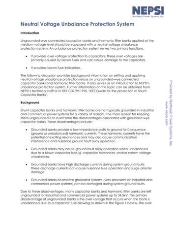
Neutral Voltage Unbalance Protection SystemIntroductionUngrounded-wye connected capacitor banks and harmonic filter banks applied at themedium voltage level should be equipped with a neutral voltage unbalanceprotection system. An unbalance protection system serves two primary functions: It provides over voltage protection to capacitors. These over voltages areprimarily caused by blown fuses and can cause damage to the capacitors. It provides blown fuse indication.BackgroundShunt capacitor banks and harmonic filter banks are not typically grounded in industrialand commercial power systems for a variety of reasons. The main reason for keepingthem ungrounded is to overcome the disadvantages associated with grounded wyecapacitor banks. These disadvantages include: Grounded banks provide a low-impedance path to ground for 0-sequence(ground or unbalanced) harmonic currents. These harmonic currents have thepotential of exciting resonances and may also cause communicationinterference and nuisance ground fault relay operation. Grounded banks may cause ground fault relay operation when unbalanceddue to a blown capacitor fuse(s), capacitor tolerances, and/or system voltageunbalances. Grounded banks have high discharge currents during system ground faults.These discharge currents can cause nuisance fuse operation and surge arresterdamage. Grounded banks on resistive grounded systems (very prevalent on industrial andcommercial power systems) can be damaged during system ground faults.Due to these disadvantages, many capacitor banks and harmonic filter banks are leftungrounded for industrial and commercial power systems up to 34.5kV. The primarydisadvantage of ungrounded banks is the over voltage that occurs when the bank isunbalanced due to a capacitor fuse blowing as shown in the Figure 1 below. The overProvided by Northeast Power Systems, Inc.www.nepsi.comThe following discussion provides background information on setting and applyingneutral voltage unbalance protection relays on ungrounded-wye connectedcapacitor banks and harmonic filter banks. It also serves as an introduction to NEPSI’sunbalance protection system. Further information on this topic can be obtained fromNEPSI’s technical staff or in IEEE C37.99-1990, "IEEE Guide for the protection of ShuntCapacitor Banks".
voltage appears across the remaining capacitors on the phase in which the fuse hasopened. The over voltage can be as high as 50%, depending upon bank configuration,and can reduce the life and permanently damage the remaining capacitors. Inaddition, the kvar output of the bank is reduced, and can cause the industrial orcommercial customer to be hit with a power factor penalty. For this reason, neutralvoltage unbalance protection should be considered.Neutral Voltage Unbalance Protection ConsiderationsThere are many technical considerations when setting and applying a neutral voltageunbalance protection system. The following bullets list the major considerations. Theymay not all be obtainable for every bank configuration. The unbalance protection system should coordinate with the individualcapacitor unit fuses such that the fuses operate to isolate a defective capacitorunit before the bank is switched out of service, and thus provide a convenientvisual means of locating the defective capacitor unit. Where possible, the unbalance protection system should be sensitive enough toalarm for the loss of one or more capacitors, but trip out for a loss of sufficient oradditional capacitor units that will cause an over voltage in excess of 110% onthe remaining capacitors. The unbalance protection system should have a time delay of at least 0.5seconds to overcome false operations due to inrush, ground faults on the line,lightning, switching of nearby equipment, and other transient unbalanceconditions.Provided by Northeast Power Systems, Inc.www.nepsi.comFigure 1 - Over voltage Caused by capacitor fuse blowing
The unbalance protection system should have a lockout feature to preventautomatic reclosing of the capacitor bank switching device. If the capacitor bank is not equipped with an over voltage relay, the unbalanceprotection system should be set with consideration given to the maximumcontinuous system operating voltage. To allow for the effects of inherent unbalance, the unbalance protection systemshould be set to alarm at one-half the level of neutral displacement determinedfor the desired alarm condition. To allow for the effects of inherent unbalance, the unbalance protection systemshould be set to trip at a level of neutral displacement that will not cause acapacitor over voltage in excess of the manufacturer’s recommendedmaximum continuous operating voltage.Figure 2 - Graph of Neutral-Ground Voltage and Per Unit Overvoltage for UngroundedCapacitorand Harmonic Filter Banks with Blown FusesProvided by Northeast Power Systems, Inc.www.nepsi.comFigure 2 below can help in meeting the above considerations. The figure shows that a28% loss in phase kvar can result in a 10% over voltage. This is the ANSI/IEEE continuousover voltage limit for standard off-the-shelf shunt capacitors. Other limits are shown forsetting the time-delay requirements on the relay.
NEPSI’s Neutral Unbalance Protection SystemThe figure below shows NEPSI’s neutral unbalance relay protection scheme designedfor ungrounded-wye connected capacitor banks and harmonic filter banks. Theprotective scheme consists of a time delay over voltage relay or meter relay and aneutral to ground potential sensing device.The neutral to ground potential sensing device is actually a resistive voltage divider andis selected for the lowest voltage ratio attainable, while still being able to withstandtransient and continuous over voltage conditions in order to obtain the maximumunbalance detection sensitivity. The device is also rated for full line potential since it cansee full line potential during energization.Provided by Northeast Power Systems, Inc.www.nepsi.comFigure 3 - Typical Neutral Voltage Unbalance Protection System for a 13.8kV Capacitor BankEither an over voltage relay or over voltage meter relay is available from NEPSI. Bothrelays serve the same function. The meter relay, however, allows the protectionengineer the ability to monitor the "ambient" neutral voltage from inherent unbalances.This allows the relay to be set above the inherent neutral voltage and will help eliminatenuisance tripping and alarming. The over voltage meter relay is equipped with twoindependent relay outputs that can be set to trip at different levels. The first level canbe set to alarm for a blown fuse, while the second level can be set to trip the bank offline for damaging over voltages.For more information on the above protection system and other available from NEPSI,contact NEPSI or the nearest NEPSI sales representative.
Northeast Power Systems, Inc.66 Carey RoadQueensbury, New York 12804Phone: 518-792-4776Fax: 518-792-5767E-mail: sales@nepsi.comWebsite: www.nepsi.comCopyright 1999 - 2012 Northeast Power Systems, Inc.Provided by Northeast Power Systems, Inc.www.nepsi.com
relays serve the same function. The meter relay, however, allows the protection engineer the ability to monitor the "ambient" neutral voltage from inherent unbalances. This allows the relay to be set above the inherent neutral voltage and will help eliminate nuisance tripping and alarming. The over voltage meter relay is equipped with two