Transcription
EVINRUDE ICON CONCEALED SIDE MOUNTREMOTE CONTROL USER’S GUIDETABLE OF CONTENTSDeclaration of Conformity . . . . . . . . . . . . . . . . . . . . . . . . . . . . . . . . . . . . . . . . . . . . . . . . 2Safety Information . . . . . . . . . . . . . . . . . . . . . . . . . . . . . . . . . . . . . . . . . . . . . . . . . . . . . 3ICON REMOTE CONTROL Features . . . . . . . . . . . . . . . . . . . . . . . . . . . . . . . . . . . . . . . . 4ICON Single Lever Concealed Side Mount Remote Control . . . . . . . . . . . . . . 4Operation . . . . . . . . . . . . . . . . . . . . . . . . . . . . . . . . . . . . . . . . . . . . . . . . . . . . . . . . . . . . . 5Emergency Stop Lanyard . . . . . . . . . . . . . . . . . . . . . . . . . . . . . . . . . . . . . . . . . 6Master Power/Key Switch . . . . . . . . . . . . . . . . . . . . . . . . . . . . . . . . . . . . . . . . . 6Station Select . . . . . . . . . . . . . . . . . . . . . . . . . . . . . . . . . . . . . . . . . . . . . . . . . . . 7Switch Panel . . . . . . . . . . . . . . . . . . . . . . . . . . . . . . . . . . . . . . . . . . . . . . . . . . . . 8START/STOP Switch . . . . . . . . . . . . . . . . . . . . . . . . . . . . . . . . . . . . . . . . . . . . . 8Shift and Throttle Control . . . . . . . . . . . . . . . . . . . . . . . . . . . . . . . . . . . . . . . . . 9Control Lever . . . . . . . . . . . . . . . . . . . . . . . . . . . . . . . . . . . . . . . . . . . . . . . . . . . 9FORWARD Gear . . . . . . . . . . . . . . . . . . . . . . . . . . . . . . . . . . . . . . . . . . . . . . . . . 9REVERSE Gear . . . . . . . . . . . . . . . . . . . . . . . . . . . . . . . . . . . . . . . . . . . . . . . . . . 9NEUTRAL . . . . . . . . . . . . . . . . . . . . . . . . . . . . . . . . . . . . . . . . . . . . . . . . . . . . . . . 9THROTTLE . . . . . . . . . . . . . . . . . . . . . . . . . . . . . . . . . . . . . . . . . . . . . . . . . . . . . 10NEUTRAL Throttle Switch . . . . . . . . . . . . . . . . . . . . . . . . . . . . . . . . . . . . . . . . 10RPM Adjustment . . . . . . . . . . . . . . . . . . . . . . . . . . . . . . . . . . . . . . . . . . . . . . . . 10Trim and Tilt Switch . . . . . . . . . . . . . . . . . . . . . . . . . . . . . . . . . . . . . . . . . . . . . 11Control Lever Trim and Tilt Switch . . . . . . . . . . . . . . . . . . . . . . . . . . . . . . . . . 11Station Protect . . . . . . . . . . . . . . . . . . . . . . . . . . . . . . . . . . . . . . . . . . . . . . . . . 11Indicator LED Brightness and Gauge Backlighting . . . . . . . . . . . . . . . . . . . . 12Control Lever Friction Adjustment . . . . . . . . . . . . . . . . . . . . . . . . . . . . . . . . . . . . . . . 12ICON Network Specifications and Information . . . . . . . . . . . . . . . . . . . . . . . . . . . . . . 13Specifications . . . . . . . . . . . . . . . . . . . . . . . . . . . . . . . . . . . . . . . . . . . . . . . . . . 13ICON Gateway Module . . . . . . . . . . . . . . . . . . . . . . . . . . . . . . . . . . . . . . . . . . . 13ICON Network Hubs . . . . . . . . . . . . . . . . . . . . . . . . . . . . . . . . . . . . . . . . . . . . . 13Accessory Power Relay Kit . . . . . . . . . . . . . . . . . . . . . . . . . . . . . . . . . . . . . . . 14Engine Identity Numbers . . . . . . . . . . . . . . . . . . . . . . . . . . . . . . . . . . . . . . . . . 14Frequently Asked Questions . . . . . . . . . . . . . . . . . . . . . . . . . . . . . . . . . . . . . . . . . . . . 15Troubleshooting . . . . . . . . . . . . . . . . . . . . . . . . . . . . . . . . . . . . . . . . . . . . . . . . . . . . . . 16ICON Fault Messages . . . . . . . . . . . . . . . . . . . . . . . . . . . . . . . . . . . . . . . . . . . . . . . . . . 17ICON System Diagram . . . . . . . . . . . . . . . . . . . . . . . . . . . . . . . . . . . . . . . . . . . . . . . . . . 18Product Warranty . . . . . . . . . . . . . . . . . . . . . . . . . . . . . . . . . . . . . . . . . . . . . . . . . . . . . . 20Index . . . . . . . . . . . . . . . . . . . . . . . . . . . . . . . . . . . . . . . . . . . . . . . . . . . . . . . . . . . . . . . . 22Notes . . . . . . . . . . . . . . . . . . . . . . . . . . . . . . . . . . . . . . . . . . . . . . . . . . . . . . . . . . . . . . . . 231
DECLARATION OF CONFORMITY Application of Council Directives:Directive 94/25/EC as amended by 2003/44/EC – Recreational-CraftThis product has been designed to be compliant with the above Directive.Maximum performance, and compliance with the EMC Directive, can only be ensured by correct installation. It is strongly recommended that the installation conforms with the followingstandards:Applicable Standards ISO 8846 Small Craft-Electrical DevicesProtection against ignition of surrounding flammable gases.ISO International Standards OrganizationThis device meets or exceeds the applicable ABYC, ISO, and USCG safe boating rules, regulations, standards, and guidelines.SAFE BOATING ON THE WEBU.S. Coast Guard (US)www.uscg.milU.S. Power Squadron (US)www.usps.orgNational Safe Boating Council (US)www.safeboatingcouncil.org/Canadian Coast Guard (CA)www.ccg-gcc.gc.caThe Royal National Lifeboat Institution (UK)www.rnli.org.ukThe Boat Safety Scheme (UK)www.boatsafetyscheme.comSafe Boating Australia (AU)www.safeboating.org.auNSW Maritime (AU)www.maritime.nsw.gov.auMarine Safety Victoria (AU)www.marinesafety.vic.gov.auMaritime Safety Queensland (AU)www.msq.qld.gov.au/Transport South Australia (AU)www.transport.sa.gov.au/Recreational Boating Safety (AU)www.dpi.wa.gov.au/imarine/19078.asp2
X EVINRUDE ICON CONCEALED SIDE MOUNT REMOTE CONTROL USER’S GUIDESAFETY INFORMATIONThis User’s Guide uses the following signalwords identifying important safety messages.DANGERIndicates a hazardous situationwhich, if not avoided, will result indeath or serious injury.WARNINGIndicates a hazardous situationwhich, if not avoided, could result indeath or serious injury.CAUTION Indicates a hazardoussituation which, if not avoided, couldresult in minor or moderate injury.NOTICE Indicatesaninstructionwhich, if not followed, could severelydamage engine components or otherproperty.IMPORTANT: Identifies information that willhelp with assembly and operation of the product.This User’s Guide contains essential information to help prevent personal injury and damage to equipment. Use the ICON User’sGuide in combination with the boat and engine operator’s guides. Always follow safetyand operation information.Be careful! Human error is caused by manyfactors: carelessness, fatigue, overload, preoccupation, unfamiliarity of operator with theproduct, drugs and alcohol to name a few.Damage to your boat and outboard can befixed in a short period of time, but injury ordeath, has a lasting effect.WARNINGThis device should not be used as anavigational aid to prevent collision,grounding, boat damage, or personal injury. When the boat is moving, water depth may change tooquickly to allow time for you to react.Always operate the boat at very slowspeeds if you suspect shallow wateror submerged objects.WARNINGThis product contains lead, a chemical known to the State of Californiato cause cancer, birth defects, andother reproductive harm.Read and familiarize yourself with the complete ICON Remote Control User’s Guide before attempting to start the outboard.3
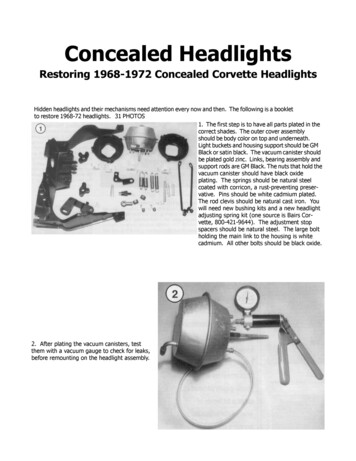
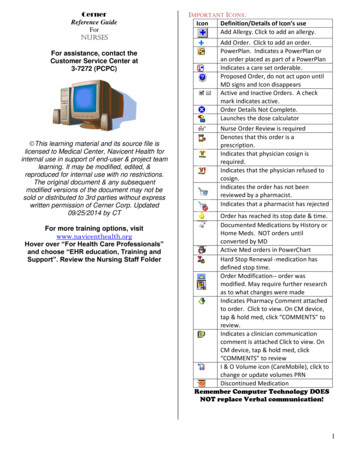
ICON REMOTE CONTROL FEATURESThe ICON single lever concealed side mount remote control is used in single engine installations. Use the ICON single lever concealed side mount remote control for single station installations.345672 NRPM–10079674FeatureFunction1Control LeverControls shift and throttle function for outboard.2Master Trim SwitchPress to adjust trim setting of all outboards.3Switch PanelContains Neutral Throttle, RPM and START /STOP switches.4START/STOP SwitchPress to START or STOP the engine.5NEUTRAL Throttle Switch (N)Press to disengage shift function. Allows for throttle onlyfunction.6NEUTRAL Indicator LEDTurns yellow when control lever is shifted into NEUTRALposition.7RPM SwitchPress or – to make slight adjustments to engine speed.
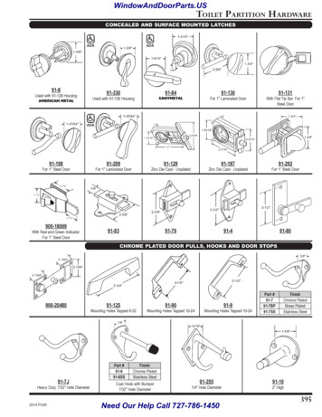
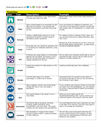
X EVINRUDE ICON CONCEALED SIDE MOUNT REMOTE CONTROL USER’S GUIDEOPERATIONOperators should be familiar with nautical orientation.This User’s Guide often identifies outboards, parts or procedures using terms shown in the diagram below.STARBOARDFORWARDPORTAFT0080025
OperationEmergency Stop LanyardSnap the emergency stop lanyard to a secureplace on the operators clothing or life vest –not where it might tear away instead of activating the stop switch.RUNOFF11. Emergency stop lanyard005499WARNINGEmergency stop lanyard MUST besecurely attached to the operator,and clip MUST be installed on master power/key switch. DO NOT operate outboard with clip removed fromswitch, except in an emergency.Disconnecting the clip of the emergency stoplanyard from the master power/key switch willstop all engines and prevent the boat from becoming a runaway if the driver moves beyondthe range of the lanyard. If the lanyard is toolong, it can be shortened by knotting it or looping it. DO NOT cut and retie the lanyard.WARNINGAvoid knocking or pulling clip off thestop switch during normal boating.Avoid bumping the key if operatingwithout the clip on the switch. Theresulting unexpected loss of forwardmotion can throw occupants forwardcausing injury.Keep the lanyard free from obstructions and entanglements.At each outing, test the system’soperation. With the engine running,remove clip from the switch by pulling the lanyard. If the engine doesnot stop running, see your dealer.Master Power/Key SwitchPush the clip of emergency stop lanyard ontothe master power/key switch.12RUNOFF1. Clip of emergency stop lanyard2. Master power/key switch0078951121. Clip of emergency stop lanyard6007896
X EVINRUDE ICON CONCEALED SIDE MOUNT REMOTE CONTROL USER’S GUIDEIn an emergency situation the engine can berestarted without the clip in place. Follow normal starting procedure. Reinstall clip as soonas possible. See your dealer to order a spareEmergency Stop Lanyard, P/N 176288.Station SelectNote: Position control lever in the NEUTRALposition to start or stop outboard. A NEUTRAL indicator Light Emitting Diode (LED) located on the switch panel will turn ON toindicate control lever is in NEUTRAL position.N1Station select is the process of activating a remote control station during system power up.REVFWDCAUTION If Station Protect isenabled, a unique key sequence must beentered to activate the station. SeeStation Protect on page 11.Turn the master power/key switch to the RUNposition.11. NEUTRAL position008005RUNOFF1 NRPM–1. RUN position007894The master power/key switch turns power ONand OFF to the: ICON control network Outboard NMEA 2000/gauge network Boat accessories (requires Accessory Power Relay Kit, P/N 765296)1. NEUTRAL indicator LED008003In single station installations, the remote control activates automatically.7
OperationSwitch PanelA switch panel is located at the operator station. The switch panel contains the START/STOP switch, a NEUTRAL switch and anRPM switch.Press and release the STOP symbol of switchto stop the outboard. N N–1RPMRPM–1. STOP symbolSwitch Panel008003008003Turn the master power/key switch to the OFFposition.START/STOP SwitchPress the START symbol of switch to start theoutboard. Crank the engine no longer than 20seconds.1RUNOFF1 NRPM1. OFF position–007895Note: Turning the master power/key switch tothe OFF position also stops the outboard andto turns off power to the station.1. START symbol008003NOTICE The starter motor can be damaged if operated continuously for morethan 20 seconds.Upon start-up, release the switch.8
X EVINRUDE ICON CONCEALED SIDE MOUNT REMOTE CONTROL USER’S GUIDEShift and Throttle ControlREVERSE GearIMPORTANT: Carefully check the function of Move the control lever to the reverse position.all control and engine systems before leaving The NEUTRAL indicator LED turns OFF andthe dock. DO NOT shift the engine into FOR- the outboard shifts into REVERSE (REV)WARD or REVERSE while the engine is gear.stopped. Shift ONLY when the engine is runNning.REVFWDControl Lever1Control lever shift and throttle range is asshown.NEUTRALFORWARD15 15 REVERSE40.5 85.5 Fuottle FFull Thro tthrll TleVRE1. REVERSE position008005NEUTRALMove the control lever to the NEUTRAL (N)position.WD008004FORWARD GearMove the control lever to the forward position.The NETRAL indicator LED turns OFF andthe outboard shifts into FORWARD (FWD)gear.The NEUTRAL indicator LED turns ON andthe outboard shifts into NEUTRAL.N1FWDREVN1FWDREV1. NEUTRAL position1. FORWARD position008005008005Note: The ICON system delays gear changesuntil engine speeds are below 1500 RPM.9
OperationTHROTTLEAfter shifting, move the control handle slowlyin the same direction to increase speed.During normal operation, the Engine Management Module (EMM) of the outboard limits engine speed to 1200 RPM while in NEUTRAL.For FORWARD gear, move control lever in a Return the control lever to the NEUTRAL position and press the N switch to deactivateforward direction to increase speed.NEUTRAL throttle switch. The NEUTRAL inFor REVERSE gear, move control lever in an dicator LED stops flashing.aft direction to increase speed.Use NEUTRAL throttle for warm-up and toReverse throttle range is limited to a maxi- perform the long-term storage (winterization)procedure. See Outboard Operator’s Guidemum of 60% power.and I-Command User’s Guide.FORWARDNEUTRAL15 REVERSENote: During the long-term storage/winterizing procedure, engine speed will be between1200 to 2600 RPM. Refer to LONG-TERMSTORAGE (WINTERIZATION) in outboard’sOperator’s Guide.15 40.5 85.5 FTullleotthrVRERPM AdjustmentThe RPM adjustment switch allows the operator to gradually adjust engine RPM.WDottle FFull Thr008004NEUTRAL Throttle SwitchThe NEUTRAL throttle switch (N) allows operation of the throttle without shifting the outboard into FORWARD or REVERSE gear.RPM adjustment range is limited to 5% of thethrottle setting. Each press of the RPM switchchanges throttle setting 1%. The adjustmentrange is approximately 100 to 200 RPM depending on engine speed.IMPORTANT: To use the RPM adjustmentfeature, the control lever MUST be in FORWARD gear and engine speed must be above500 RPM.Press the N switch. The NEUTRAL indicator Press the side of the RPM switch to inLED flashes. Advance the control lever in a crease engine speed. Press the – side of theforward direction to increase engine speed.RPM switch to decrease engine speed.1 NRPM–1. N switch10008003
X EVINRUDE ICON CONCEALED SIDE MOUNT REMOTE CONTROL USER’S GUIDEReposition the control lever and start the process again for further adjustment. To cancelthe RPM adjustment switch setting move thecontrol lever to a faster or slower position.Note: “Station Protect” is normally used indual station applications and this feature limits use of control stations. Station Protectmust be set up during installation. Dealersmust use Evinrude Diagnostics software toreprogram the Engine Management Module(EMM) to turn ON this option.2To activate the station, press the side of theRPM switch and the N switch in this sequence:1) Press the side of the RPM switch first,2) Press the side of the RPM switch second,3) Press the N switch third and4) Press the side of the RPM switch last.RPM–1. side of RPM switch2. – side of RPM switchWhen Station Protect is turned ON, a uniquekey sequence must be entered to activate astation and start, run and control all outboards.1 NStation Protect008003Trim and Tilt SwitchControl Lever Trim and Tilt SwitchThe trim and tilt switch on the control lever allows the operator to trim or tilt the outboard. Press the UP side of the trim and tilt switchto trim the outboard up. Press the DOWN side of the trim and tiltswitch to trim the outboard down.121 NRPM–21. side of RPM switch2. N switch1. UP side of trim and tilt switch2. DOWN side of trim and tilt switch00800300800611
Control Lever Friction AdjustmentCONTROL LEVER FRICTIONADJUSTMENTIndicator LED Brightness andGauge BacklightingThe RPM switch also allows the operator toadjust the brightness of indicator LEDs on the Check control lever friction adjustment. Whencontrol base and the backlighting of the properly adjusted, the control lever shouldhave low friction to allow easy movement inNMEA 2000/I-Command gauges.the throttle range, and not allow vibration toIMPORTANT: The control lever MUST be in change the throttle setting.the NEUTRAL position.Remove cover from control lever. Use a 5/32To change the brightness of indicator LEDs in (4 mm) hex tool to adjust friction adjustmentscrew. Turn the adjustment screw clockwiseand gauge backlighting, press:to increase the friction or counterclockwise to the side of the RPM switch to brightenreduce the friction. the – side of the RPM switch to dim.Throttle Friction1 This adjustment is used to increase or reducethe force required to move the control leverthrough the throttle range. NRPM–221. side of RPM switch2. – side of RPM switch00800311. Cover2. Throttle friction adjustment screw12008008
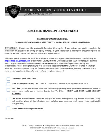
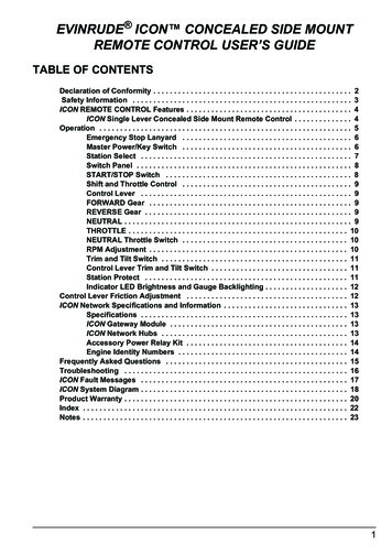
X EVINRUDE ICON CONCEALED SIDE MOUNT REMOTE CONTROL USER’S GUIDEICON NETWORK SPECIFICATIONS AND INFORMATIONSpecifications9 to 18 VDCSupply Voltage (Boat System)5 VDCOperating Voltage (ICON Control Network)1, 2, 3, 4, or 5 outboardsEngine ControlContinuousReverse Polarity ProtectionFuse, Network10 Amp, ATO Type, P/N 967545Fuse, Master Power/Key Switch3 Amp, ATO Type, P/N 764538Fuse, Electronic Servo Module30 Amp, Minifuse Type, P/N 5032630Fuse, Accessory Power Relay Kit10 Amp, Minifuse Type, P/N 514766Proprietary, based on NMEA 2000 standardNetwork Interface-13 to 167 F (-25 to 75 C)Operating Temperature RangeMaximum Current Draw10µA(Master Power/Key Switch turned OFF)ICON Gateway ModuleICON Network HubsThe ICON gateway module provides network ICON network hubs are used to connect bussdata to the NMEA 2000 network and I-Com- cables to remote controls, gateway module,mand gauges.master power/key switch and to other deviceson the network.The gateway module receives power from thenetwork power cable. When the gateway is Two hubs MUST be installed in the ICON netpowered and receiving data from the network work. See ICON System Diagram onthe LED on the gateway module turns ON.page 18.Protective covers must be used to seal unused connections.111. LED on gateway module2007913The gateway module provides fuel level monitoring for up to four fuel tanks when connected to fuel level senders.1. ICON network hub2. Protective cover00794513
ICON Network Specifications and InformationAccessory Power Relay KitAccessory Power Relay Kit, P/N 765296,must be used to power boat accessorieswhich require switched B . This kit is used inplace of connecting accessories to the “A” terminal of the key switch.Each outboard is identified by an engine identity plug installed in its ESM.The first time the ICON system is turned ON,it automatically checks engine identity numbers. During this time, the controls will not respond to operator inputs. Allow approximately3 seconds per engine for this check to complete.Check the engine identity plug number and besure the engine identity plug is installed asoutlined in the table.Accessory Power Relay Kit0079401Engine Identity NumbersEngine identity numbers are assigned to theElectronic Servo Module (ESM) and EngineManagement Module (EMM) of each outboard. Engine identity numbers allow theICON network to correctly control the outboards.1. Engine identity plug007525IMPORTANT: Do not exchange ESMs orEMMs between outboards. Severe engineNote: Engine identity numbers assignment is damage can result from improper replacecritical in multiple engine installations. Single ment of ESM or EMM.engine installations normally require nochange to identity number assignment.The table below lists typical engine identitynumber enterPortCenterNumber ofOutboardsPortIdentity Numbers11222334
X EVINRUDE ICON CONCEALED SIDE MOUNT REMOTE CONTRO
ment Module (EMM) of the outboard limits en-gine speed to 1200 RPM while in NEUTRAL. Return the control lever to the NEUTRAL po-sition and press the N switch to deactivate NEUTRAL throttle switch. The NEUTRAL in-dicator LED stops flashing. Use NEUTRAL throttle for warm-up and to