Transcription
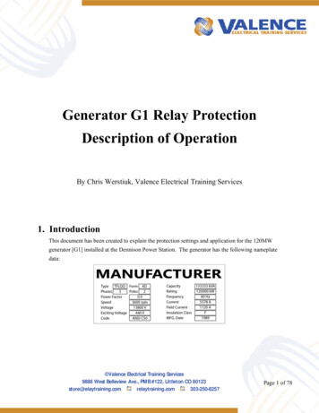
PROTECTIONGenerator ProtectionM‑3420Integrated Protection System for Generators of All SizesUnit shown with optional M‑3920 Target Module and M‑3931 HMI(Human-Machine Interface) Module Microprocessor-based Generator Protection systemprovides 17 protective relay functions Individually programmable input contacts can beprogrammed to activate any one of eight output contacts Local and remote communications capability for bothmonitoring and control functionsIndustry Leader Since 1969Made in the USA
M‑3420 Generator Protection Relay – SpecificationProtective Functions Overexcitation (V/Hz) protection (24)Phase Undervoltage protection (27)Sensitive dual-setpoint, reverse power detection suitable for sequential tripping (32)Dual-zone, offset-mho loss-of-field protection (40)Sensitive negative-sequence overcurrent protection and alarming (46)Instantaneous overcurrent (50) protectionInadvertent generator energizing protection (50/27)Generator breaker failure protection (50BF)Neutral inverse time overcurrent (51N)Instantaneous overcurrent (50N) protectionThree-phase inverse time overcurrent (51V)Phase overvoltage (59)Generator ground fault protection (59N)VT fuse-loss detection and blocking (60FL)Four-step over/underfrequency protection (81)Generator phase differential (87)Ground differential (87GD) protectionStandard Features Eight programmable outputs and six programmable inputsOscillography recording32-target storageMetering of all measured parametersTwo RS-232 and one RS-485 communications portsStandard 19" rack-mount designRemovable printed circuit board and power supplyBoth 50 and 60 Hz models availableBoth 1 and 5 A rated CT inputs availableAdditional trip inputs for externally connected devicesM‑3800A IPScom Communications SoftwareS-3400 IPScom Communications Software for Windows 7 or laterIRIG-B time synchronizationIncludes Modbus and BECO 2200 protocolsOptional Features Redundant power supplyM‑3920 Target ModuleM‑3931 HMI ModuleM‑3801A IPSplot Oscillograph Analysis Software4-Wire RS-485 Connection–2–
M‑3420 Generator Protection Relay – SpecificationPROTECTIVE ntAccuracy†100 to 200%1% 1%30 to 8160 Cycles1 Cycle 25 CyclesInverse Time #1–#4——100 to 200%1% 1%1 to 1000 to 910.1——1 to 999 Sec.(from threshold of trip)1 Sec. 3 Cycles or 1%Volts/HzDefinite TimePickup #1, #2Time Delay #1, #224Inverse TimeCharacteristic Curves3φPickupTime Dial: Curve #1Time Dial: Curves #2–#4Reset RateThe percent pickup is based on nominal VT secondary voltage and nominal system frequency settings.The pickup accuracy stated is only applicable from 10 to 80 Hz, 0 to 180 V, and 100 to 150% V/Hz.RMS UndervoltagePickup #1, #25 to 200 V1V273φTime Delay #1, #21 to 8160 Cycles1 Cycle 0.5 V or 0.5% 0.8 V or 0.75%* 20 Cycles or 1%*** When both RMS and line‑ground‑to‑line‑line is selected.**When RMS (total waveform) is selected, timing accuracy is 20 cycles or 1%; when DFT (fundamental RMS) isselected, accuracy is -1 to 3 cycles or 1%.Directional Power32Pickup #1, #23φTime Delay #1, #2-3.000 to 3.000 PU0.001 PU 0.002 PU or 2%1 to 8160 Cycles1 Cycle 16 Cycles or 1%The per-unit pickup is based on nominal VT secondary voltage and nominal CT secondary current settings.Loss of Field (dual-zone offset-mho characteristic)Circle Diameter #1, #2Offset #1, #2400.1 to 100.0 Ω0.1 Ω(0.5 to 500.0 Ω) 0.1 Ω or 5%( 0.5 Ω or 5%)-50.0 to 50.0 Ω0.1 Ω(-250.0 to 250.0 Ω) 0.1 Ω or 5%( 0.5 Ω or 5%)3φTime Delay #1, #21 to 8160 Cycles1 CycleVoltage Control(positive sequence)5 to 200 V1V 0.5 V or 0.5%Directional ElementFixed at -13 ——-1 to 3 Cycles or 1%Voltage control for each zone can be individually enabled.Select the greater of these accuracy values. Values in parentheses apply to 1 A CT secondary rating.†–3–
M‑3420 Generator Protection Relay – SpecificationPROTECTIVE FUNCTIONS Accuracy†Negative Sequence OvercurrentDefinite TimePickup3 to 100%1%Time Delay1 to 8160 Cycles1 Cycle 0.5% at 5 A( 0.5% at 1 A)-1 to 3 Cycles46Inverse TimePickup3 to 100%1%3φTime Dial Setting (K I22t)Definite MaximumTime to TripReset Time (Linear)1 to 951600 to 65,500 Cycles1 Cycle4 minutes(from threshold of trip)— 0.5% at 5 A( 0.5% at 1 A) 3%-1 to 3 Cycles or 1%—Pickup is based on the nominal CT secondary current.Instantaneous OvercurrentPickup503φ1.0 to 240.0 A0.1 A(0.2 to 48.0 A)Trip Time Response2 Cycles— 0.1 A or 3%( 0.02 A or 3%) 2 CyclesInstantaneous Overcurrent, Neutral50NPickup1.0 to 240.0 A0.1 A(0.2 to 48.0 A)3φTrip Time Response 0.1 A or 3%( 0.02 A or 3%)2 Cycles— 2 Cycles0.50 to 15.00 A(0.10 to 3.00 A)0.01 A 0.1 A or 2%( 0.02 A or 2%)40 to 130 V1V 0.5 VPick-up Time Delay1 to 8160 Cycles1 Cycle-1 to 3 Cycles or 1%Drop-out Time Delay1 to 8160 Cycles1 Cycle-1 to 3 Cycles or 1%0.10 to 10.00 A(0.02 to 2.00 A)0.01 A 0.1 A or 2%( 0.02 A or 2%)0.10 to 10.00 A(0.02 to 2.00 A)0.01 A 0.1 A or 2%( 0.02 A or 2%)1 to 8160 Cycles1 Cycle-1 to 3 Cycles or 1%Inadvertent ePickupBreaker Failure50BF-PhPickup50Phase CurrentBF 503φBF-NNeutral CurrentTime Delay50BF can be initiated from designated output contacts or status inputs.Select the greater of these accuracy values. Values in parentheses apply to 1 A CT secondary rating.†–4–
M‑3420 Generator Protection Relay – SpecificationPROTECTIVE FUNCTIONS Accuracy†Inverse Time Overcurrent, Neutral51NCharacteristic CurveTap Setting3φDefinite Time/Inverse/Very Inverse/Extremely Inverse0.5 to 12.00 A(0.10 to 2.40 A)0.01 A—0.5 to 11.00.1 3 Cycles or 3%Time Dial SettingInverse Time Overcurrent, with Voltage Control or Voltage RestraintCharacteristic CurveTap Setting51V3φDefinite Time/Inverse/Very Inverse/Extremely Inverse0.5 to 12.00 A(0.10 to 2.40 A)0.01 A—Time Dial Setting0.5 to 11.00.1 3 Cycles or 3%Voltage Control (VC)orVoltage Restraint (VR)5 to 200 V1V 0.5 V or 0.5%Linear Restraint——RMS OvervoltagePickup #1, #25 to 200 V1V593φTime Delay #1, #21 to 8160 Cycles1 Cycle 0.5 V or 0.5% 0.8 V or 0.75%* 20 Cycles or 1%**Accuracy applies to values below 180 V pickup.* When both RMS and line‑ground‑to‑line‑line is selected.**When RMS (total waveform) is selected, timing accuracy is 20 cycles or 1%; when DFT (fundamental RMS) isselected, accuracy is -1 to 3 cycles or 1%.RMS Overvoltage, Neutral59NPickup #1, #2Time Delay #1, #25.0 to 200.0 V0.1 V1 to 8160 Cycles1 Cycle 0.5 V or 0.5%-1 to 3 Cycles or 1%VT Fuse-Loss Detection60FLA VT fuse-loss condition is detected by using the positive and negative sequence componentsof the voltages and currents. VT fuse-loss output can be initiated from internally generatedlogic or from input contacts.Time Delay1 to 8160 Cycles1 Cycle50.00 to 67.00 Hz40.00 to 57.00 Hz*0.01 Hz2 to 65,500 Cycles1 Cycle-1 to 3 Cycles or 1%FrequencyPickup #1,#2,#3,#481Time Delay #1,#2,#3,#4 0.02 Hz-2 to 3 Cycles or 1%The pickup accuracy applies to 60 Hz models at a range of 57 to 63 Hz, and to 50 Hz models at a range of 47 to 53Hz. Beyond these ranges, the accuracy is 0.1 Hz.* This range applies to 50 Hz nominal frequency models.Select the greater of these accuracy values. Values in parentheses apply to 1 A CT secondary rating.†–5–
M‑3420 Generator Protection Relay – SpecificationPROTECTIVE FUNCTIONS Accuracy†Phase Differential CurrentMinimum Pickup873φPercent SlopeTime Delay0.20 A to 3.00 A0.01 A 0.10 A or 5%(0.04 to 0.60 A)( 0.02 A or 5%)1 to 100%1%1 to 8160 Cycles1 Cycle 2%-1 to 3 Cycles or 1%When a time delay of 1 cycle is selected, the response time is less than 1 /2 cycles.1Ground (zero sequence) DifferentialPickup87GD3φTime DelayCT Ratio Correction (RC)0.2 to 10 A(0.04 to 2.00 A)††0.01 0.1 or 5%1 to 8160 Cycles1 Cycle-1 to 3 Cycles or 1%0.10 to 7.990.01The 87GD function is provided primarily for low-impedance grounded generator applications. This function operatesas a directional differential. If 3I0 or In is extremely small, the directional element is disabled.External FunctionsEXTTwo functions are provided for externally connected devices to trip through the M‑3420 toprovide additional logic and target information. Any one or more of the input contacts (INPUT1through INPUT6) can be programmed to activate designated output contacts after a selectedtime delay.Time Delay #1, #21 to 8160 Cycles1 Cycle-1 to 3 Cycles or 1%Nominal Voltage60 to 140 V1V—Nominal Current0.50 to 6.00 A0.01 A—Nominal SettingsVT ConfigurationLine-Line / Line-Ground/Line-Ground to Line-Line*Seal-In Delay2 to 8160 Cycles1 cycle-1 to 3 Cycles or 1%* When Line-Ground to Line-Line is selected, the relay internally calculates the line-line voltage from the line-groundvoltages for all voltage-sensitive functions. This Line-Ground to Line-Line selection should only be used for a VTnominal secondary voltage of 69 V (not 120 V).Select the greater of these accuracy values. Values in parentheses apply to 1 A CT secondary rating.†–6–
M‑3420 Generator Protection Relay – SpecificationMeteringThe M‑3420 provides metering of voltages (phase, neutral and sequence quantities), currents (phase, neutraland sequence quantities), real power, reactive power, power factor and impedance measurements.Metering accuracies are:Voltage: 0.5 V or 0.5%, whichever is greater 0.8 V or 0.75%, whichever is greater (when both RMS andline‑ground to line‑line are selected)Current:5 A rating, 0.1 A or 3%, whichever is greater1 A rating, 0.02 A or 3%, whichever is greaterPower : 0.01 PU or 2%, whichever is greater(real and reactive)Frequency: 0.02 Hz (from 57 to 63 Hz for 60 Hz models; from 47 to 53 Hz for 50 Hz models)Oscillograph RecorderThe oscillograph recorder provides comprehensive data recording of all monitored waveforms, storing upto 170 cycles of data. The total record length may be configured by the user for 1, 2, 3 or 4 partitions. Thesampling rate is 16 times the power system nominal frequency (50 or 60 Hz). When armed, the recorder istriggered either via the designated status inputs, trip outputs, or via serial communications. When armedyet untriggered, the recorder continuously stores waveform data, keeping the most recent data in memory.When triggered, the recorder continues to store data in memory for a user-defined, post-trigger delay period.Target StorageA total of 32 targets can be stored. The information will include the function(s) operated, the functions pickedup, input/output contact status, timer status, time stamp, and phase and neutral currents at the time of trip.CalculationsCurrent and Voltage RMS Values: Uses discrete Fourier transform (DFT) algorithm on sampled (16 times percycle) voltage and current signals to extract fundamental frequency phasors for M‑3420 calculations. RMSphase voltages for the 59 and 27 functions (when total RMS is selected), and the 24 function are obtainedusing the time domain approach to obtain accuracy over a wide frequency band. When the RMS option isselected, the magnitude calculation is accurate over a wide frequency range (10 to 80 Hz). When the DFToption is selected, the magnitude calculation is accurate near nominal frequency (50 or 60 Hz).Power Input OptionsNominal 110/120/230/240 Vac, 50/60 Hz, or nominal 110/125/220/250 Vdc. UL rating 85 Vac to 265 Vac andfrom 80 Vdc to 288 Vdc. Burden 20 VA at 120 Vac/125 Vdc. Withstands 300 Vac or 300 Vdc for 1 second.Nominal 24/48 Vdc, operating range from 18 Vdc to 56 Vdc. Burden 20 VA at 24 Vdc and 20 VA at 48 Vdc.Withstands 65 Vdc for 1 second.An optional redundant power supply is available.Sensing InputsFour Voltage Inputs: Rated nominal voltage of 60 Vac to 140 Vac, 60 Hz/(50 Hz optional). Will withstand240 V continuous voltage and 360 V for 10 seconds. Source voltages may be line-to-ground or line-to-lineconnected. Phase sequence ABC/ACB is selectable. Voltage transformer burden less than 0.2 VA at 120 V.Seven Current Inputs: Rated nominal current (IR) of 5.0 A or 1.0 A (optional), 60 Hz/(50 Hz optional). Willwithstand 2IR continuous current and 100IR for 1 second. Current transformer burden is less than 0.5 VAat 5 A (5 A option), or 0.3 VA at 1 A (1 A option).–7–
M‑3420 Generator Protection Relay – SpecificationStatus Input ContactsThe status inputs, INPUT1 through INPUT6, can be programmed to block any of the M‑3420 functions, totrigger the oscillograph recorder, or to operate one or more outputs. The status inputs should be dry contactsand are internally connected (wetted) to a 24 Vdc power supply. To provide breaker status LED indication onthe front panel, the INPUT1 status input contact must be connected to the 52b breaker status contact. Theminimum current value to initiate/pickup an Input is 25 mA.Output ContactsThe eight programmable output contacts (six form "a" and two form "c"), the power supply alarm outputcontact (form "b"), and the self-test alarm output contact (form "c") are all rated as per IEEE C37.90 (SeeTests and Standards section for details).Any of the M‑3420 functions can be individually programmed to activate any one or more of the eightprogrammable output contacts.Target/Status Indicators and ControlsThe RELAY OK LED reveals proper cycling of the microcomputer. The BRKR CLOSED LED will turn on whenthe breaker is closed (when the 52b contact input is open). The OSC TRIG LED indicates that oscillographicdata has been recorded in the unit's memory. The TARGET LED will turn on when any of the relay functionsoperate. Pressing and releasing the TARGET RESET button resets the target LED if the conditions causingthe operation have been removed. Pressing and holding the TARGET RESET button displays the presentpickup status of the M‑3420 functions. The PS1 and PS2 LEDs will remain on as long as power is appliedto the unit and the power supply is operating properly.CommunicationCommunications ports include rear panel RS‑232 and RS-485 ports, a front panel RS-232 port, and anIRIG‑B port. The communications protocol implements serial, byte-oriented, asynchronous communication,providing the following functions when used with the Microsoft Windows-compatible M‑3800A or S-3400(Windows 7 or later) IPScom Communications Software package. MODBUS and BECO 2200 protocols aresupported, providing: Interrogation and modification of setpointsTime-stamped trip target information for the 32 most recent eventsReal-time metering of all quantities measured.Downloading of recorded oscillographic data (Not available with MODBUS)IRIG-BThe M‑3420 can accept a modulated IRIG‑B time clock synchronization signal through a BNC connectorprovided at the rear of the unit. The IRIG‑B time synchronization information is used to correct the hour,minute, seconds and milliseconds information.HMI Module (optional)Local access to the M-3420 is provided through an optional M-3931 HMI (Human-Machine Interface) Module,allowing for easy-to-use, menu-driven access to all functions via six buttons and a 2-line by 24 characteralphanumeric LCD. Features of the HMI Module include the following: User-definable access codes allow three levels of securityInterrogation and modification of setpointsTime-stamped trip target information for the 32 most recent eventsReal-time metering of all quantities measured–8–
M‑3420 Generator Protection Relay – SpecificationTarget Module (optional)An optional M-3920 Target Module provides 24 target and 8 output LEDs. Appropriate target LEDs will lightwhen the corresponding M‑3420 function operates. The targets can be reset with the TARGET RESET button.The OUTPUT LEDs indicate the status of the programmable output contacts.Type Tests and StandardsThe M‑3420 Generator Protection relay complies with the following type tests and standards:Voltage WithstandDielectric WithstandIEC 255-53,500 Vdc for 1 minute applied to each independent circuit to earth3,500 Vdc for 1 minute applied between each independent circuit1,500 Vdc for 1 minute applied to IRIG-B circuit to earth1,500 Vdc for 1 minute applied between IRIG-B to each independent circuitImpulse VoltageIEC 255-55,000 V pk, /- polarity applied to each independent circuit to earth5,000 V pk, /- polarity applied between each independent circuit1.2 by 50 µs, 500 ohms impedance, three surges at 5 second intervalsInsulation ResistanceIEC 255-5 40 MegaohmsElectrical EnvironmentElectrostatic Discharge TestIEC 1000-4-2Class 4 (8 kV) – point contact dischargeFast Transient Disturbance TestIEC 1000-4-4Class 4 (4 kV, 2.5 kHz)Surge Withstand CapabilityIEEE C37.90.12,500 V pk-pk oscillatory applied to each independent circuit to earth2,500 V pk-pk applied between each independent circuit5,000 V pk Fast Transient applied to each independent circuit to earth5,000 V pk Fast Transient applied between each independent circuitRadiated SusceptibilityIEEE C37.90.225-1000 Mhz @ 35 V/mOutput Contacts RatingsIEEE C37.90UL 50830 A make for 0.2 seconds at 250 Vdc resistive8 A carry at 120 Vac, 50/60 Hz6 A break at 120 Vac, 50/60 Hz0.1 A break at 125 Vdc0.1 A break at 120 Vac–9–
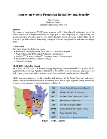
M‑3420 Generator Protection Relay – SpecificationAtmospheric EnvironmentTemperatureIEC 68-2-1Cold, -20 C for 96 hoursIEC 68-2-2Dry Heat, 70 C for 96 hoursIEC 68-2-3Damp Heat, 40 C @ 93% RH, for 96 hoursMechanical EnvironmentVibrationIEC 255-21-1Vibration response Class 1, 0.5 gVibration endurance Class 1, 1.0 gCompliancecULus‑Listedper 508– NRGU.E128716 Industrial Control Equipment– NRGU7.E128716 Industrial Control Equipment Certified for CanadaCAN/USA C22.2 No. 14‑M91cULus‑Listedper 508A – Table SA1.1 Industrial Control PanelsExternal ConnectionsM‑3420 Generator Protection Relay External Connections are illustrated in Figures 1, 2, and 3 on thefollowing pages.PhysicalSize: 19.00" wide x 5.21" high x 10.00" deep (48.3 cm x 13.2 cm x 25.4 cm)Mounting: The unit is a standard 19", semiflush, three-unit high, rack-mount panel design, conforming toANSI/EIA RS-310C and DIN 41494 Part 5 specifications. Vertical or horizontal panel-mount options areavailable.Contact Beckwith Electric for optional GE L‑2/Westinghouse FT‑41 retrofit panel vertical mounting details.Environmental: For flat surface mounting on a Type 1 enclosure, rated to 70 C surrounding air ambient.Approximate Weight: 13 lbs (7.7 kg)Approximate Shipping Weight: 15 lbs (11.3 kg)Recommended Storage ParametersTemperature: 5 C to 40 CHumidity: Maximum relative humidity 80% for temperatures up to 31 C, decreasing to 31 C linearly to50% relative humidity at 40 C.Environment: Storage area to be free of dust, corrosive gases, flammable materials, dew, percolating water,rain and solar radiation.See M-3420 Instruction Book, Appendix E, Layup and Storage for additional information.Patent & WarrantyThe M‑3420 Generator Protection Relay is covered by U.S. Patents 5,592,393 and 5,224,011.The M‑3420 Generator Protection Relay is covered by a five year warranty from date of shipment.Specification subject to change without notice.–10–
–11–424344IN347491315IC1A ,NO M50165253171956205266118 - 5 6V8 5 - 2 6 5V60-PS 2 463-18 - 5 6V8 5 - 2 6 5V62 293F3F130SERIAL NO.28PS127OUT PUT S25311F233PS134F43 A MP,MP 2 5 0 V ( 3 A B)PS2232FIELD GND connection is intended for future use.596247.58Ic23The self-test relay is energized when the relay has performed all self-tests successfully.57226.Ib721The power supply relay (P/S) is energized when the power supply is functioning properly.5 A ,NO M55External ConnectionsIa81854RAT ED C URRENT51INS ELF- T EST14A LA RMSP/ S12U.S. PATENT 5,592,393, 5,224,01148IBINRT NFigure 146IA!115.VN10IN1(5 2b)45IN2INPUT SIN49All relays are shown in the de-energized state.5 0 / 6 0 HzRA T ED V O L T A GE6 0 - 140V41IN584.40IN67ONLY dry contacts must be connected to inputs (terminals 5 through 10 with 11 common) because these contact inputs are internally wetted.Application of external voltage on these inputs may result in damage to the units.39VC VC ATX63.38VB CVB-RS 4 8 5COM 3 5FIRMWARE:To comply with UL listing requirements, terminal block connections must be made with #22–12 AWG solid or stranded copper wire inserted inan AMP #324915 (or equivalent) connector. Wire insulation must be rated at 75 C minimum. Terminal block connections 1 through 34 must betightened to 12 in‑lbs torque. Terminal block connections 35 through 63 must be tightened to 8.0 in‑lbs, minimum, 9.0 in-lbs, maximum torque.Over torquing may result in terminal damage.37ARX460 Hz2.36VVA B-350 HzMODEL:Output contacts #1 through #4 are high speed operation contacts.35COM 2RS 2 3 22W A RNING! C O NT A C T W IT H T ERMINA L S MA Y C A US E EL EC T RIC S HO C KDanger! Contact avec les ter minaux peut causer un choc électriqueFO R C O NT A C T RA T INGS S EE INS T RUC T IO N MA NUA L1. NOTES:!IRIG- B16 19 0 118 t h AV E NO .727- 5 4 4 - 23 26L A RGO , FL 3 3 7 7 3BEC KW IT H ELECT RIC CO . INC .M‑3420 Generator Protection Relay – Specification
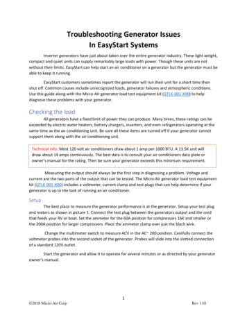
M‑3420 Generator Protection Relay – SpecificationUtility SystemM-3420 TypicalConnection Diagram52UnitThis function provides control forthe function to which it points.NOTE: Some functions aremutually exclusive; seeInstruction Book for 251V87GD40465050BFN50N51NCTCTRLow-Impedance Groundingwith Overcurrent StatorGround Fault ProtectionM-3420VT59NRHigh-Impedance GroundingFigure 2One-Line Connection Diagram–12–
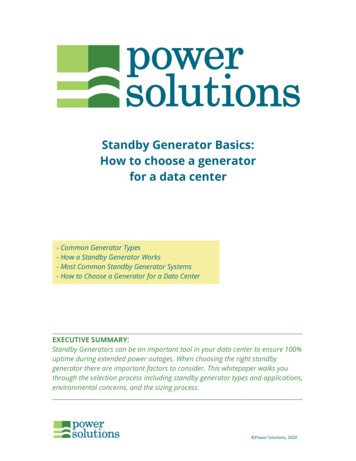
M‑3420 Generator Protection Relay – SpecificationUTILITY SYSTEMAB NATECONNECTIONSOtherRelaysM-34201052bThree VT Wye-WyeConnection11ABC1Two VT Open-DeltaConnection1GeneratorOtherRelaysM-3420A B C58595657545542 4340 4138 3942 43M-342040 4138 39M-3420Alternate VT connectionsRequired generator breaker status input (52b). Contact is closedwhen generator breaker is open. Use unit breaker contact if nogenerator breaker present.Output contact pairs designated by user.Alarm output can be grouped to a single alarm at discretion of user.Available control output to supervise other relays for VT Fuse Losscan be designated.Input contact number is designated by user.WARNING: ONLY dry contacts must be connected becausethese contact inputs are internally wetted. Application of externalvoltage on these inputs may result in damage to the E: M-3420 current terminal polarity marks ( ) indicate "entering" currentdirection when primary current is "from" the generator. If CT connectionsdiffer from those shown, adjust input terminals.High Impedance GroundingExample of Control / Output Connections DC:M-3420 24 V48 VPOWER 60 62SUPPLY 61 63 11OR-DC: 110 V125 V220 V250 VAC: 110 V120 V230 V240 LUREALARMPOWER OKSTATUSALARMVTFUSELOSS52G52Ga4EXTERNAL INPUTSFigure 3ALARM OUTPUTSThree-Line Connection Diagram–13–CONTROLOUTPUTSTRIP OUTPUT
M‑3420 Generator Protection Relay – .23]ACTUAL5.28[13.41]RECOMMENDED CUTOUT WHEN RELAY ISNOT USED AS STANDARD RACK 51]0.35[0.89]0.40 [1.02] X 0.27[0.68] Slot (4X)2.25[5.72]1.48[3.76]Standard 19" Horizontal Mount ChassisNOTE: Dimensions in brackets are in centimeters.Figure 4Mounting Dimensions–14–
M‑3420 Generator Protection Relay – ]6.19[15.7]2.25[5.72]0.35[0.89]1.97[5.0]0.28 [0.71]Dia. S18.30[46.51]OUT 1OUT 3OUT 5OUT 7OUT 2OUT 4OUT 6OUT PS 2PS 1TARGETDIAGBRKRCLOSEDOSC.TRIGRELAYOKTIMESYNCCOM 117.50[44.45]Recommended cutout when relay is not used asstandard rack mount and is panel cut out mounted.10.20[25.91]19.00[48.26]NOTE: Dimensions in brackets are in centimeters.Figure 5Vertical Mounting Dimensions NOTE: Panels for vertical mounting are available. When mounted vertically, the target module will belocated at the top and all front-panel text will be horizontally aligned. Consult Beckwith ElectricCo. for details.–15–
BECKWITH ELECTRIC CO., INC.6190 - 118th Avenue North Largo, Florida 33773-3724 U.S.A.PHONE (727) 544-2326 FAX (727) electric.comISO 9001:2015 2001 Beckwith Electric Co.Printed in U.S.A.800-3420-SP-17MC106/20
M-3420 Generator Protection Relay - Specification PROTECTIVE FUNCTIONS Device Setpoint Number FunctionRangesIncrement Accuracy† Volts/Hz Definite Time Pickup #1, #2 100 to 200% 1% 1% Time Delay #1, #2 30 to 8160 Cycles 1 Cycle 25 Cycles Inverse Time Characteristic Curves Inverse Time #1-#4 — — Pickup 100 to 200% 1% 1%