Transcription
PowerHour webinar series for consulting engineersExperts you trust. Excellence you count on.NEC 2017 Requirements for Generator SetOvercurrent ProtectionJanuary 24th, 2017 11:00 PDT / 13:00 CDT(1PDH issued by Cummins)
Welcome!PowerHour is designed to help our engineer partners to Keep up to date on products, technology, and codes and standards development Interact with Cummins experts and gain access to ongoing technical support Participate at your convenience, live or on-demand Earn PDHTechnical tips: Audio is available through teleconference, or your computer (don’t forget to unmute) You are in “listen only” mode throughout the event Use the WebEx Q&A Panel to submit questions, comments, and feedbackthroughout the event. We will provide sufficient Q&A time after presentation If you lose audio, get disconnected, or experience a poor connection, pleasedisconnect and reconnect Report technical issues using the WebEx Q&A Panel, or emailpowergenchannel@cummins.com2
Meet your panelistsCummins presenter:Munir KaderbhaiApplication EngineerCummins Power SystemsCummins PanelistRich ScrogginsTechnical AdvisorCummins Power SystemsCummins facilitator:Tom Bakritzes,Global Sales Training ManagerYour local Cummins contacts: AZ, ID, NM, NV: Carl Knapp (carl.knapp@cummins.com), Rocky Mountain Region CO, MT, ND, UT, WY: Joe Pekarek (joe.a.pekarek@cummins.com), Rocky Mountain Region IL, IA, NB, SD: John Kilinskis (john.a.kilinskis@cummins.com), Central Region WI, MN, ND: Michael Munson (michael.s.munson@cummins.com), Central Region MO, KS: Earnest Glaser (earnest.a.glaser@cummins.com), Central Region TX: Scott Thomas (m.scott.thomas@cummins.com), Gulf Region FL, GA, SC, NC and Eastern TN: Robert Kelly (robert.kelly@cummins.com), South Region IN, KY, OH, TN, WV: Thomas Stadulis (thomas.stadulis@cummins.com), East Region NY, NJ, CT, PA, MD: Charles Attisani (charles.attisani@cummins.com ): East Region For other states and territories, email powergenchannel@cummins.com or visit http://power.cummins.com/sales-service-locator3
Course ObjectivesParticipants will be able to: Explain generator excitation systems and their effect on fault currentperformance Identify basic generator set overcurrent protection requirements in orderto specify the correct protection equipment. Describe the NEC requirements for selective coordination, generatordisconnect, arc flash energy reduction and separation of circuits inorder to evaluate different means for achieving code compliance. Identify recent important codes changes to NFPA70 NEC 2017pertaining to the topics listed above.4
Agenda Generator performance under overcurrent conditions– Review of generator excitation systems– Alternator Decrement Curves– PowerCommand AmpSentry functionality Describe NEC requirements for– Overload Protection– Selective coordination– Arc Energy Reduction– Generator disconnect requirements– Separation of circuits requirements5
Generator Excitation Systems – Self (Shunt) ExcitedKey Point: AVR may nothave the capability tosupport the fault currentlong enough to cleardownstream faults as themain field in thealternator may collapse.6
Generator Excitation Systems – Separately Excited - PMGKey Point: Ability toprovides sustained shortcircuit (SSC) currentduring fault conditionswhich prevent the fieldfrom collapsing and allowsfor faults downstream toclear7
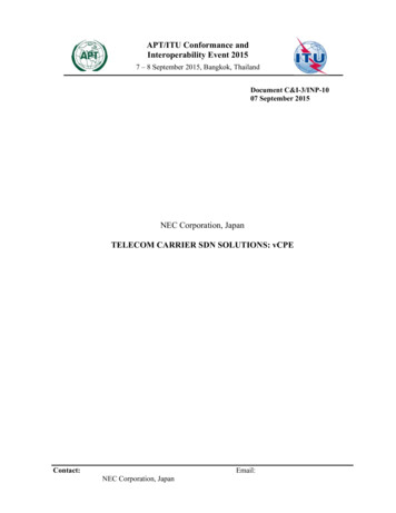
Alternator Performance Under a Fault - DecrementCurve (Separately Excited)Current is a function of theAVR, Excitation System andalternator electro-magneticdesign.I3ph, pu 1/Xd”Key points: Alternator fault currentdecays, it doesn’t remainconstant like fault currentfrom a transformer System design softwaretools such as SKM accountfor thisI3ph, pu (1/Xd” - 1/Xd’)*e(-t/Td”) (1/Xd’ - 1/Xd)*e(-t/Td’) 1/XdThree phase fault characteristics8
Decrement Curve MultipliersSingle phase faultsresult in higher levelsof fault currentUnbalanced faults stressalternator rotor damperwindingsSustained short circuit current isdetermined by the AVR andexcitation systemInstantaneous Fault CurrentI3ph, p.u 1/Xd”ISLG, p.u 3/( Xd” X2 X0 3 Rf)ILL, p.u 1.732/(Xd” X2)9IEEE Std 142-2007 (Green Book)1.7.1 “Unlike the transformer the three sequence reactances from a generator are notequal. The zero sequence reactance has the lowest value and the positive sequencereactance varies as a function of time. Thus, a generator will usually have a higherinitial ground fault current than three phase fault current if the generator has a solidlygrounded neutral.”
Per Unit Reactances Alternator reactances are published usingthe alternator kVA rating as a base Fault current calculations need to use thesame base or the reactances need to beconverted to the genset kW rating base AmpSentry uses the genset standby kVArating as a baseExample:Generator Set: 2500kW DQKAN,Alternator LVSI804X, 60Hz, 480VGenerator Set kVA 3125Alternator kVA 4464X”dgenset 0.119/4464*3125 0.08310
NEC Requirements Overload protection of generator and conductors (Article445.12 and 445.13) Selective coordination (Articles 700.28 & 701.27 & 708.54) Arc Energy Reduction (Article 240.87) Disconnecting Means for Generators (Article 445.18) Separation of Emergency Circuits (Article 700.10)11
Generator Overload Protection Code Requirement (NFPA 70 445.12(A))– Generators, except AC generator exciters, shall be protected fromoverloads by inherent design, circuit breakers, fuses, protective relaysor other identified overcurrent protective means suitable for theconditions of use.Exception: Where deemed vital to the operation of the electricalsystem the overload sensing devices (shall) be permitted to beconnected to an annunciator or alarm Overload. Operation of equipment in excess of normal, full-loadrating, or of a conductor in excess of rated ampacity that, when itpersists for a sufficient length of time, would cause damage ordangerous overheating. A fault, such as a short circuit or groundfault, is not an overload.12
Cable Overload Protection N Article 445.13 (A): The ampacity of the conductors from thegenerator terminals to the first distribution device(s) containingovercurrent protection shall be not less than 115% of the nameplatecurrent rating of the generator.Exception: Where the design and operation of the generator preventoverloading, the ampacity of the conductors shall not be less than100% of the nameplate current rating of the generator. Article 240.21 (G): Conductors from generator terminals that meet445.13 shall be permitted to be protected by the generator overloadprotective device(s) required by 445.12.13
N 445.13(B) Generators. Ampacity of Conductors.Overcurrent Protection Provided Where the generator set is equipped with a listed overcurrentprotective device or a combination of a current transformer andovercurrent relay, conductors shall be permitted to be tapped from theload side of the protected terminals in accordance to 240.21(B)14
Generator Set OverloadProtection - 445.12 (A)Conductor Size/Overload Protection 445.13 (A), 240.21 (G)Taps on main generatorset feeder conductor 445.13(B)15
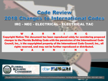
Is the Protection There?CABLE THERMALDAMAGE CURVECABLE THERMALDAMAGE CURVE Generator and cable is required tobe protected– Thermal damage isn’t total failureGENERATORTHERMAL DAMAGECURVE Conventional wisdom is not correct Any breaker used is susceptible tosome level of nuisance trips due toinstantaneous function16TIME (SECONDS)– Most common protection is moldedcase breaker(s) withthermal/magnetic trip– Fully rated breakers don’t protectgenerator– Need fully adjustable electronic tripon the MCCB or other listedprotective device1010.10.051310AMPS (TIMES RATED)100
Inherently Designed Overcurrent Protection - AmpSentry Protective Relay Overcurrent protection integral to the Cummins PowerCommandControl System UL listed device Provides overcurrent protection by shutting down the genset beforealternator thermal damage occurs If current exceeds 300% of rated, AmpSentry decreases excitationto regulate current at 300% until:– Fault is cleared by a downstream breaker– Or generator set is shut down based on: Thermal damage curve for 3 phase fault 2 seconds for L-G fault 5 seconds for L- L fault17
AmpSentry Trip Curve Library Files available in:– SKM POWER*TOOLS– EasyPower SuitesLink to access the trip curve ipment-library18
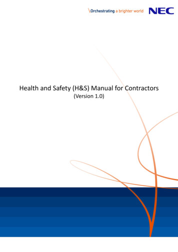
3-Phase Fault Response with AmpSentry OvercurrentRelay%Current3 Phase L1-L2-L3 Short: AmpSentry Regulation and Shutdown500450400350300250200150100500Peak Current: IR/X”dAlt %Standby Max LineCurrentRegulates at 3X RatedShuts down before damage0510tim e, sec191520
Voltage Recovery (3-phase fault) with AmpSentry Overcurrent Relay3 Phase L1-L2-L3 Short and Recovery: L-N Voltages vs. TimePercent of Nominal Voltage12010080Alt L1-N Voltage (%)60Alt L2-N Voltage (%)40Alt L3-N Voltage (%)2000246tim e, sec20810
AmpSentry and Neutral Grounding Resistors Neutral Grounding Resistors are not required to protect generator sets thatare equipped with the AmpSentry protective relay NGR’s may still be necessary as part of the overall grounding and protectionscheme AmpSentry will not limit instantaneous ground fault current In the event of a L-G fault AmpSentry will regulate current in the faultedphase at 300% of rated current for 2 seconds at which time the generator setwill shut down (or until some protective device clears the fault)21
Online Certification AmpSentry is UL Listed as a protective ISEXT/1FRAME/index.htm22
AmpSentryTM UL Label23
What is Selective Coordination? NEC Article 100 Definition– Selective Coordination: Localization of an over-current condition torestrict outages to the circuit or equipment affected, accomplished bythe choice of over-current protective devices and their ratings orsettings Selective Coordination is required for emergency,legally required standby and critical operations powersystems circuits– NEC 700.32, 701.27, and 708.54 “ power system(s) shall beselectively coordinated with all supply side OCPDs.” over-current24
Selective CoordinationWithout Selective CoordinationOPENSOPENSNOT AFFECTEDUNNECESSARYPOWER LOSS25With Selective CoordinationFaultNOTAFFECTEDFault
Demonstrating Selective Coordination Engineers will use software packagessuch as SKM to demonstratecoordination on their projects AmpSentry is included in the latestversion of SKM and EasyPowerNo overlap - breakers arecoordinated in this regionof the curveTrip curves overlap – thesebreakers are notcoordinated for high levelsof fault current26
“Overlap Exception” Circuit breaker manufacturers candemonstrate coordination with theirown products Published coordination charts Drives project to use consistentdevices through the entire projectPOTENTIALPROBLEMAREA27
AmpSentry and Selective Coordination Amp Sentry simplifiescoordination by regulating faultcurrent until the downstreambreaker clears Genset mounted molded casecircuit breaker present challengesin coordinating with downstreambreakers The inclusion of AmpSentry inSKM and EasyPower softwaresimplifies design of coordinatedsystems28
(N) NFPA 70 240.87 (B) Arc EnergyReduction“Where the highest continuous current tripsetting is 1200A or higher one of thefollowing or approved equivalent means (toreduce clearing time) shall be provided Energy-reducing maintenance switchingwith local status indicator an energy reducing maintenance switchallows a worker to set a circuit breaker triptime to “no intentional delay”29
Generator Set Circuit Breaker Arc Flash Protection Example – Square D P and H Micrologic solidstate trip units (P and H) Energy Reduction Maintenance Setting (ERMS)Local ERMS Switch30ERMS Label on Trip UnitERMS Switch “OFF” and “ON” Mode
Generator Set Integrated Arc Flash Protection –AmpSentry Maintenance Mode AmpSentry Maintenance Mode similarto circuit breaker arc energy reducingfunction Instantaneous generator set shutdownin the event of a short circuit, bypassingall time delays Can also be configured to shunt trip adownstream breaker Enabled by a customer input or byconnecting InPower service tool Complies with NEC requirement for arcenergy reduction31
AmpSentry and NEC Arc Flash Reduction Arc energy calculation depends onseveral site specific factors–Available fault current, arc interrupting time,system voltage, grounding method, conductorgap, working distance Maintenance Mode reduces arcinterrupting time–Shuts down genset within 50 msec–Configurable output can shunt trip a breaker32
Generator Set Disconnect Means and Shutdown of PrimeMover (N) NFPA 70-2014, 445.18– (A) Disconnecting Means - Generators shall be equipped withdisconnect(s), lockable in the open position– (B) Shutdown of Prime Mover (1) Provisions to disable all prime mover start control circuits (2) Initiate a shutdown mechanism that requires a mechanical reset Provisions for (B) permitted to satisfy requirements for (A) if capable of beinglocked out.– (C) Generator Installed in Parallel Provisions of 445.18(A) shall be capable of isolation the generator outputterminals from the paralleling equipment. Disconnect means shall not be required to located at the generator.33
Generator Set Disconnect Means and Shutdown of PrimeMover (cont.)E-stop switch with lockableshroud34Disconnect starter battery andlockout
Lock Out Tag Out NFPA 70E Requires that equipment must be disconnected from allsources of electrical supply– Neither the E-stop switch or a genset mounted breaker is sufficient tomeet LOTO requirements Genset has two sources of electrical supply– Battery charging system– Utility or paralleled genset LOTO procedure should include– Removing and locking out battery cable– Locking out breaker that feeds charging system– Locking out paralleling breaker that connects utility or paralleledgenset35
Separation of Emergency TIONNFPA70-2014 700.10 (B)(5)(c):Emergency circuits shall not originate from the same vertical switchgearsection, vertical switchboard section, panelboard enclosure or individualdisconnect enclosure as other circuits Could meet the requirement with individual enclosures for each breaker– Selective Coordination requires breaker selection as a system36
n of CircuitsTO AUTOMATIC TRANSFERSWITCHES & LOADSPER NECNFPA70-2014 700.10 (B)(5)(d):It shall be permissible to utilize single or multiple feeders to supplydistribution equipment between an emergency source and the pointwhere the combination of emergency loads are separated from all otherloads37
RecommendationsNo Main Line Circuit BreakerRequired For Alternator ProtectionATS400 Amps800 AmpsUtilityEssentialLoadsATS400 AmpsEquipmentLoads Specify:– Alternator shall be protected per the requirements of NFPA70 section 445.12.– The protection provided shall be coordinated with the thermal damage curve of the alternator. Damage curve andprotection curve shall be submitted to verify performance.– The protection shall allow operation of the generator set continuously at its rated output.– The protection equipment provided shall be 3rd party certified to verify performance.– The protection shall include arc energy reducing maintenance switching Based on this spec, typical equipment provided might be:– Molded case circuit breaker with solid state trips– Inherent Overcurrent protection38
Generator Protection Summary Generator set mounted thermal magnetic breakers may notprotect the generator and will be difficult to coordinate withdownstream devices AmpSentry is a UL listed overcurrent protective relay integral toCummins generator controls– Included in SKM and EasyPower software– Meets NFPA 70 240.87 requirements for arc energy reducing maintenanceswitching The generator E-stop switch meets NEC disconnect requirements Mounting breakers off of the generator simplifies separation ofcircuits requirements39
Q&A Type your questions, comments, feedback in the WebExQ&A box. We will get to as many questions as we can We will publish consolidated FAQ along with presentationand webinar recording on powersuite.cummins.comYour local Cummins contacts: AZ, ID, NM, NV: Carl Knapp (carl.knapp@cummins.com), Rocky Mountain Region CO, MT, ND, UT, WY: Joe Pekarek (joe.a.pekarek@cummins.com), Rocky Mountain Region IL, IA, NB, SD: John Kilinskis (john.a.kilinskis@cummins.com), Central Region WI, MN, ND: Michael Munson (michael.s.munson@cummins.com), Central Region MO, KS: Earnest Glaser (earnest.a.glaser@cummins.com), Central Region TX: Scott Thomas (m.scott.thomas@cummins.com), Gulf Region FL, GA, SC, NC and Eastern TN: Robert Kelly (robert.kelly@cummins.com), South Region IN, KY, OH, TN, WV: Thomas Stadulis (thomas.stadulis@cummins.com), East Region NY, NJ, CT, PA, MD: Charles Attisani (charles.attisani@cummins.com ): East Region For other states and territories, email powergenchannel@cummins.com or visit http://power.cummins.com/sales-service-locator40
Closing Watch out for a follow-up email including– A Link to webinar recording– A PDH Certificate– A 2-minute survey link. Tell us how we did and how we can improve Visit powersuite.cummins.com for– PowerHour webinar recording, presentation and FAQ archive– Other Cummins Continuing Education programs– Sizing and spec development tool41
NEC 2017 Requirements for Generator Set Overcurrent Protection January 24th, 2017 11:00 PDT / 13:00 CDT . (Green Book) 1.7.1 "Unlike the transformer the three sequence reactances from a generator are not . Code Requirement (NFPA 70 445.12(A)) -Generators, except AC generator exciters, shall be protected from .