Transcription
GENERATORPROTECTIONFundamentals and ApplicationSan Francisco ChapterElectrical Workshop: Measurement, Safety, and Protection“Knowledge is Power. Protect Your Important Assets!”Friday, May 29, 2015Presented by:6190 118th Avenue North, Largo, FL 33773 (727) 544-2326 www.BeckwithElectric.comProducts Defined by You, Refined by Beckwith
Presenter Contact InfoWayne HartmannVP, Protection and Smart Grid SolutionsBeckwith Electric ayne Hartmann is VP, Protection and Smart Grid Solutions forBeckwith Electric. He provides Customer and Industry linkage toBeckwith Electric’s solutions, as well as contributing expertise fornapplication engineering, training and product development.Before joining Beckwith Electric, Wayne performed in application, sales and marketing managementcapacities with PowerSecure, General Electric, Siemens Power T&D and Alstom T&D. During thecourse of Wayne's participation in the industry, his focus has been on the application of protection andcontrol systems for electrical generation, transmission, distribution, and distributed energy resources.Wayne is very active in IEEE as a Senior Member serving as a Main Committee Member of the IEEEPower System Relaying Committee for 25 years. His IEEE tenure includes having chaired the RotatingMachinery Protection Subcommittee (’07-’10), contributing to numerous standards, guides,transactions, reports and tutorials, and teaching at the T&D Conference and various local PES andIAS chapters. He has authored and presented numerous technical papers and contributed to McGrawHill's “Standard Handbook of Power Plant Engineering, 2nd Ed.”1Generator ProtectionObjectives Review of generator construction and operationReview grounding and connectionsDiscuss IEEE standards for generator protectionExplore generator elements Internal faults (in the generator zone) Abnormal operating conditions Generator zone Out of zone (system) External faults Discuss generator and power system interaction21
Generator ProtectionObjectives Tripping considerations and sequentialtripping Discussion of tactics to improve security anddependability Generator protection upgrade considerations Advanced attributes for security, reliability andmaintenance use Review Setting, Commissioning and EventInvestigation Tools Q&A3Generator ProtectionGenerator Construction:Simple Bock DiagramPrime Mover(Mechanical Input)iaibicGDC Field SourceThree-PhaseElectricalOutput42
Generator ProtectionApplying Mechanical Input34211.2.3.4.Reciprocating EnginesHydroelectricGas Turbines (GTs, CGTs)Steam Turbines (STs)5Applying FieldStatic Exciter DC is induced in the rotor AC is induced in the stator36
Rotor StylesCylindrical (Round)Generator ProtectionSalient Cylindrical rotor seen in Recips, GTs and STs Salient pole rotor seen in Hydros More poles to obtain nominal frequency at low RPM Eq: f [RPM/60] * [P/2] [RPM * P] / 1207Generator ProtectionCylindrical Rotor & Stator84
Generator ProtectionCylindrical Rotor & Stator9Cylindrical Rotor & Stator105
Generator ProtectionSalient Pole Rotor & Stator11Generator ProtectionSalient Pole Rotor & Stator126
Generator ProtectionGenerator Behavior During Short Circuits13Generator ProtectionShort-Circuit CurrentGenerator Short-Circuit Current Decay147
Generator ProtectionEffect of DC OffsetsCurrentCurrentCurrentThree-Phase Fault15Generator ProtectionGrounding Techniques Why Ground? Improved safety by allowing detection of faultedequipment Stop transient overvoltages Notorious in ungrounded systems Ability to detect a ground fault before a multiphaseto ground fault evolves If impedance is introduced, limit ground faultcurrent and associated damage faults Provide ground source for other system protection(other zones supplied from generator)168
Generator ProtectionTypes of Generator GroundingSystem Low Impedance Good ground source The lower the R, the better theground source The lower the R, the moredamage to the generator oninternal ground fault Can get expensive as resistorvoltage rating goes up Generator will be damaged oninternal ground fault Ground fault current typically 200400 AGRGroundingResistor17Generator ProtectionTypes of Generator GroundingSystem High ImpedanceGSUTransformerG RNGR Neutral Grounding ResistorResistance RR Reflected ResistanceRNGRRR Creates “unit connection” System ground source obtained fromGSU Uses principle of reflected impedance Eq: RNGR RR / [Vpri/Vsec]2R Ground fault current typically 10ANeutralGroundingTransformer189
Generator ProtectionTypes of Generator GroundingSystem Compensated Creates “unit connection” Most expensiveGSUTransformer Tuned reactor, plus GSU and GroundingTransformersG System ground source obtained from GSU Uses reflected impedance from groundingtransformer, same as high impedancegrounded system does Generator damage mitigated from groundfault Reactor tuned against generator capacitanceto ground to limit ground fault current to verylow value (can be less than 1A)ZNGIZRNeutralGroundingTransformer19Generator ProtectionTypes of Generator Grounding3Y Hybrid Impedance Grounding52G Has advantages of Low-Z and High-Zground Normal Operation87GDG Low-Z grounded machine provides groundsource for other zones under normalconditions51GHybrid Ground1VSRTripExcitation&Prime MoverR59N 51G acts as back up protection for unclearedsystem ground faultsConvertsfrom 51G is too slow to protectgeneratorforlow-Zto high-Z forinternal faultinternal generator fault Ground Fault in Machine Detected by the 87GD element The Low-Z ground path is opened by avacuum switch Only High-Z ground path is then available The High-Z ground path limits fault current toapproximately 10A (stops generator damage)1020
Generator ProtectionTypes of Generator GroundingHybrid GroundConverts from low-Zto high-Z forinternal generator fault21Generator ProtectionTypes of Generator Ground Fault Damage Following pictures show stator damage after aninternal ground fault This generator was high impedance grounded,with the fault current less than 10A Some iron burning occurred, but the damagewas repairable With low impedance grounded machines thedamage is severe2211
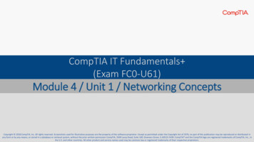
Stator Ground Fault Damage(only 10A for 60 cycles)23Generator ProtectionTypes of Generator Connections Bus or Direct Connected (typically Low Z)- Directly connected to bus- Likely in industrial, commercial, andisolated systems- Simple, inexpensive2412
Generator ProtectionTypes of Generator Connections Multiple Direct or Bus Connected(No/Low Z/High Z)BUS- Directly connected to bus- Likely in industrial, commercial,and isolated systems- Simple- May have problems withcirculating currentGGGSame type of grounding used on 1 or mutiple generators Use of single groundedmachine can help- Adds complexity to discriminateground fault source25Generator ProtectionBus (Direct) Connected2613
Generator ProtectionTypes of Generator Connections Unit Connected (High Z)- Generator has dedicated unit transformer- Generator has dedicated ground transformer- Likely in large industrial and utility systems- 100% stator ground fault protection availableBUS27Generator ProtectionTypes of Generator Connections Multiple Bus (High Z), 1 or Multiple Generators- Connected through one unit xfmr- Likely in large industrial and utility systems- No circulating current issue- Adds complexity to discriminate ground fault source Special CTs needed for sensitivity, and directional groundovercurrent elements2814
Generator ProtectionUnit Connected29Generator ProtectionGenerator Protection Overview Generators experience shorts and abnormalelectrical conditions Proper protection can mitigate damage to themachine Proper protection can enhance generationsecurity Generator Protection: Shorts circuits in the generator Uncleared faults on the system Abnormal electrical conditions may be caused by thegenerator or the system3015
Generator ProtectionGenerator Protection Overview Short Circuits In Generator Phase Faults Ground Faults On System Phase Faults Ground Faults31Generator ProtectionGenerator Protection OverviewInternal and External Short Circuits1632
Generator ProtectionGenerator Protection Overview Abnormal Operating Conditions Abnormal FrequencyAbnormal VoltageOverexcitationField LossLoss of SynchronismInadvertent EnergizingBreaker FailureLoss of Prime MoverBlown VT FusesOpen Circuits / Conductors33Generator ProtectionGenerator Protection OverviewOpenCircuitsOverexcitationLoss of FieldLoss of ower SystemGAbnormalFrequencyReverse PowerInadvertentEnergizing,Pole FlashoverBreaker FailureOverexcitationLoss ofSynchronismAbnormal Operating Conditions1734
Generator ProtectionANSI/IEEE Standards Latest developments reflected in:- Std. 242: Buff Book- C37.102: IEEE Guide for Generator Protection- C37.101: IEEE Guide for AC Generator GroundProtection- C37.106: IEEE Guide for Abnormal FrequencyProtection for Power Generating PlantsThese are created/maintained by the IEEE PES PSRC & IAS35Typical UnitConnectedGenerator(C37.102)Unit Connected,High Z Grounded3618
Stator Ground Fault Traditional stator ground fault protectionschemes include: Neutral overvoltage Various third harmonic voltage-dependentschemes These exhibit sensitivity, security andclearing speed issues that may subject agenerator to prolonged low level groundfaults that may evolve into damaging faults37Neutral Overvoltage (59G) 59G provides 95% stator winding coverage3819
Generator Protection59N ElementVoltage at Neutral(60 Hz)1.0pu0.5pu00%N50%Fault Position100%T Neutral grounding transformer (NGT)ratio selected that provides 120 to 240Vfor ground fault at machine terminals Max L-G volts 13.8kV / 1.73 7995V Max NGT volts sec. 7995V / 120V 66.39 VTR3959G System Ground Fault Issue GSU provides capacitive coupling for system ground faults intogenerator zone Use two levels of 59G with short and long time delays forselectivity Cannot detect ground faults at/near the neutral (very important)2040
59G-1 is blind tothe capacitivecoupling by theGSU.Time (cycles)Multiple 59G Element Application Short time delay 59G-2 is set to 5%, which may include theeffects of capacitive coupling by the GSU– Long time delay41Use of Symmetrical Component Quantitiesto Supervise 59G Tripping SpeedI2 spV2 spV0 sp59G spAA59G-1(Short Delay)59G sp59G-1(Short Delay)59G-259G-2(Long Delay)(Long Delay) Both V2 and I2 implementation have been applied– A ground fault in the generator zone produces primarily zero sequencevoltage– A fault in the VT secondary or system (GSU coupled ) generatesnegative sequence quantities in addition to zero sequence voltage4221
Intermittent Arcing Ground Fault Turned Multiphase4359G/27TN Timing LogicInterval and Delay Timers used together to detectintermittent pickups of arcing ground fault4422
Generator Protection59N Element45Why Do We Care About Faults Near Neutral? A fault at or near the neutral shunts the high resistance that savesthe stator from large currents with an internal ground fault A generator operating with an undetected ground fault near theneutral is a accident waiting to happen We can use 3rd Harmonic or Injection Techniques for complete(100%) coverage4623
Generator Capacitance and 3rd Harmonics 3rd harmonics areproduced by somegenerators Amount typically small Lumped capacitanceon each stator end isCS/2. CT is added at terminalend due to surge capsand isophase bus Effect is 3rd harmonicnull point is shiftedtoward terminal endand not balanced47Generator ProtectionThird-Harmonic Rotor Flux Develops in stator due to imperfections in winding and system connectionsUnpredictable amount requiring field observation at various operatingconditionsAlso dependent on pitch of the windings, which a method to define the waystator windings placed in the stator slotsRotor MMF2448
Generator ProtectionUsing Third Harmonic in GeneratorsI3h A, B, CCGenerator winding and terminalcapacitances (C) provide path forthe third-harmonic stator currentvia grounding resistorThis can be applied in protectionschemes for enhanced groundfault protection coverageR3I3h493rd Harmonic Undervoltage (27TN)0-15% CoverageNGTGSU Transformer59G27TN59NGR A fault near the neutral shunts the 3rd harmonicnear the neutral to ground Result is a third harmonic undervoltage Security issues with generator operating modeand power output (real and reactive)2550
Generator Protection3rd Harmonic in Generators:Typical 3rd Harmonic Values 3rd harmonic values tend to increase with power and VAr loadingFault near neutral causes 3rd harmonic voltage at neutral to go to zero volts51Example 3rd Harmonic Plot:Effects of MW and MVAR Loading5226
Generator Protection3rd Harmonic Voltages and Ratio Voltage53Generator Protection27TN –3rdHarmonic Neutral Undervoltage Provides 0-15% stator winding coverage (typ.) Tuned to 3rd harmonic frequency Provides two levels of setpoints Supervisions for increased security under various loadingconditions: Any or All May be Applied Simultaneously Phase Overvoltage SupervisionUnderpower BlockForward & ReverseUnder VAr Block; Lead & LagPower Factor Block; Lead & LagDefinable Power Band Block Undervoltage/No Voltage BlockVaries with loadMay vary with power flow directionMay vary with levelMay vary with lead and lagMay be gaps in outputLoading/operating variables may be Sync Condenser, VAr Sink,Pumped Storage, CT Starting, Power Output Reduction2754
Generator Protection27TN Settings and Supervision55Generator Protection100% Stator Ground Fault (59N/27TN)56Third-Harmonic Undervoltage Ground-Fault Protection Scheme28
Generator Protection100% Stator Ground Fault (59N/27TN) 101.03rd HarmonicVoltage profile inwindingVfund profile inwinding00.559N pickup27TN pickup-1000100%50%59N27TN57Overlap of Third Harmonic (27TN) with 59N RelayGenerator Protection59D – 3rd Harmonic Ratio Voltage0-15% Coverage59N85-100% CoverageVN59D3V0 Employs comparison of 3rd harmonic voltages at terminal andneutral ends These voltages are fairly close to each other One goes very low if a ground fault occurs at either end of thewinding2958
Generator Protection59D – 3rd Harmonic Ratio Voltage59Generator ProtectionStator Ground Faults: 59N, 27TN, 59D6030
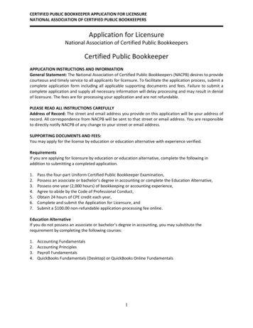
Generator Protection3rd Harmonic Voltage Decrease During an OverSpeed Condition in a 45MW Hydro Generator Typical value of 3rd harmonic (V3rd) is around 1.7V, 27TNset to pick up at 1.1V. A line breaker tripped isolating plant, and they experienceda 27TN operation. Oscillograph shows the V3rd decreased from 1.7V to 1.0Vas the frequency went from 60 Hz to 66Hz, (only 110%over speed). This is well below the 180-200% over speed condition thatis often cited as possible with hydros upon full loadrejection. What happens to 59N?61Generator Protection3rdHarmonic in Hydro Generators6231
Subharmonic Injection: 64SNatural Capacitance 20Hz injected intogrounding transformersecondary circuit Rise in real componentof injected currentsuggests resistiveground fault Ignores capacitivecurrent due to isophasebus and surge caps Coupling FilterVoltageInjectorV20HzUses it for self-diagnostic and systemintegrityINotes:Subharmonic injection frequency 20 HzMeasurementsCoupling filter tuned for subharmonic frequency63Measurement inputs tuned to respond to subharmonic frequencySubharmonic Injection: 64S Functions on-line and off-line Power and frequency independent6432
64S – Subharmonic Injection65Generator ProtectionStator Ground Faults: High Z Element Coverage6633
Stator Ground Fault:High Z Grounded Machines 95% stator ground fault provided by 59NTuned to the fundamental frequency Must work properly from 10 to 80 Hz to provide protection duringstartup Additional coverage near neutral (last 5%) provided by: 27TN: 3rd harmonic undervoltage 59D: Ratio of 3rd harmonic at terminal and neutral ends ofwinding Full 100% stator coverage by 64S Use of sub-harmonic injection May be used when generator is off-line Immune to changes in loading (MW, MVAR)67Generator ProtectionStator Ground Fault: Low Z Grounded MachinesSystem 51N element typicallyapplied Coordinate with systemground fault protection forsecurity and selectivity Results in long clearing timefor internal machine groundfault Selectivity issues with busedmachinesG51NG1R51N1R6834
Generator Protection51N: Neutral Overcurrent69Generator ProtectionDirectional Neutral Overcurrent: 67NLow-Z Grounded Generator 67N element provides selectivity on multiple busedmachine applications Requires only phase CTs, or terminal side zero-sequenceCT 67N directionalized to trip for zero-sequence (ground)current toward a generator 67N is set faster than 51N May be short definite time delay Ground current should not flow into a generator under normaloperating conditions May be applied on ungrounded machines for ground faultprotection if bus or other generators are a ground source7035
Generator ProtectionDirectional Neutral Overcurrent: 67NLow-Z Grounded GeneratorSystem3Y67N3Y67NG51NG Use with 51N on groundedmachine(s) for internal faultand system back up51NR Employ 67N to selectively clearmachine ground fault for multigenerator bus connectedarrangementsR Ground switches on allmachines can all be closed71Generator ProtectionDirectional Neutral Overcurrent: 67NLow-Z Grounded Generator Ground fault on system is detectedby grounded generator’s 51Nelement Coordinated with system relays,they should trip before 51N 67N sees fault current in the reversedirection and does not trip7236
Generator ProtectionDirectional Neutral Overcurrent: 67NLow-Z Grounded GeneratorSystem Ground fault in machine isdetected by 67N & 51N67N 67N picks up in faulted machine67NG51NG 51N picks up in faulted andunfaulted machines 67N trips fast in faulted machine51N 51N resets on faulted andunfaulted machinesRR73Generator ProtectionDirectional Neutral Overcurrent: 67NInternal Fault90Trip3IO IN18003VO VN VXBlock Trip270 Internal faults create angles of 3I0 or IN current flow into generator fromsystem that are approximately 150 degrees from 3V0 This is from reactive power being drawn in from system as well as realpower3774
Generator Protection67N: Directional Neutral Overcurrent75Generator ProtectionDirectional Neutral Overcurrent: 87GLow-Z Grounded Generator 87GD element provides selectivity on multiple busedmachine applications Requires phase CTs, or terminal side zero-sequenceCT, and a ground CT 87GD uses currents with directionalization for securityand selectivity 87GD is set faster than 51N May use short definite time delay Ground current should not flow into a generator fromterminal end under normal operating conditions Ground current should not flow unchallenged intomachine7638
Generator ProtectionTrip Characteristic – 87GDInternal Fault-3Io x IGcos (0) -3IoIG7777Generator ProtectionTrip Characteristic – 87GDExternal Fault-3Io x IGcos (0) -3IoIG787839
Generator ProtectionTrip Characteristic – 87GDOpen Breaker, Internal FaultIG setting79Generator ProtectionImproved Ground Fault Sensitivity (87GD) Direction calculation used with currents over 140mA on both sets ofCTs (3I0 and IG) Directional element used to improve security for heavy external phaseto phase faults that cause saturation When current 140mA, element uses current setting and directionalsignal When current 140mA, element uses current setting only Saturation will not occur at such low current levelsDirectional signal not required for securityAllows element to function for internal faults without phase output current(open breaker, internal fault source by generator only)8040
Generator ProtectionDirectional Neutral Overcurrent: 87GLow-Z Grounded Generator Employed 87GD toselectively clear machineground fault for multigenerator bus connectedarrangements Use with 51N on groundedmachine(s) for internal faultand system back up Ground switches on allmachines can all be closed81Generator ProtectionDirectional Neutral Overcurrent:87GLow-Z Grounded GeneratorSystem3Y3Y Ground fault inmachine is detected by87GD & 51N 51N picks up inunfaulted machine 87GD trips fast infaulted machine 51N resets onunfaulted machine87GD87GDG51N1RG51N1R8241
Generator Protection51N67NStator Ground Faults:Low Z Element Coverage87GD100%50%0% In Low-Z schemes, you cannotprovide 100% stator ground faultprotection Protection down to last 5%-10% nearneutral using 51N Protection down to last 5% using 67Nor 87GD Seletivity and high speed possiblewith 67N or 87GD with in zone faultSingle generator, with system supplying ground current,or multiple generators as ground current sourcesSingle generator, with system supplying ground current,or multiple generators as ground current sources83Field/Rotor Ground Fault Traditional field/rotor circuit ground faultprotection schemes employ DC voltagedetection Schemes based on DC principles are subject tosecurity issues during field forcing, othersudden shifts in field current and systemtransients8442
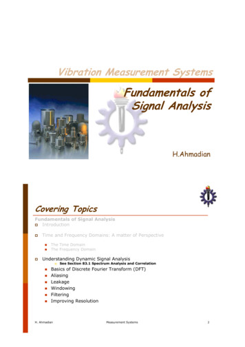
Brushed and “Brushless” Excitation“Brushless”Brushed85Field/Rotor Ground Fault (64F) To mitigate the security issues of traditionalDC-based rotor ground fault protectionschemes, AC injection based protectionmay be used AC injection-based protection ignores theeffects of sudden DC current changes in thefield/rotor circuits and attendant DC schemesecurity issues8643
DC-Based 64F87Advanced AC Injection MethodFieldExciterBreaker Square WaveGeneratorExciter–SignalMeasurement& ProcessingProtectiveRelayCouplingNetwork8844
Advanced AC Injection Method: Advantages Scheme is secure against the effects of DC transients inthe field/rotor circuit DC systems are prone to false alarms and false trips, so theysometimes are ignored or rendered inoperative, placing thegenerator at risk The AC system offers greater security so this importantprotection is not ignored or rendered inoperative Scheme can detect a rise in impedance which ischaracteristic of grounding brush lift-off In brushless systems, the measurement brush may beperiodically connected for short time intervals The brush lift-off function must be blocked during the timeinterval the measurement brush is disconnected89Generator ProtectionRotor Ground Fault Measurement Plan a shutdown to determine why impedance is lowering, versus aneventual unplanned trip! When resistive fault develops, Vf goes rement PointFIELD NG NETWORKC37 RRC35SIGNALMEASUREMENTCIRCUITTimeGEN.ROTOR-RRf Cf,Vf36MachineFrameGround45ShaftGround Brush90
Generator ProtectionBrush Lift-Off Measurement When brush lifts off,Vf goes upBrush Lift-Off VoltageVf ment PointAlarm Voltage when BrushResistance Increases dueto poor contactVALARM PROCESSORFIELD GROUNDDETECTIONSQUAREWAVEGENERATORTimeVNORMAL Normal Voltage forHealthy Brush ContactVOUTM-3921COUPLING NETWORKC37 RRC35SIGNALMEASUREMENTCIRCUITGEN.ROTOR-RRf Cf,Vf36ShaftGround BrushMachineFrameGround91Generator Protection64F: Field/Rotor Ground Faults9246
Generator Protection64F: Field/Rotor Ground Faults64B: Brush Lift Off93Generator ProtectionStator Phase Faults 87G – Phase Differential (primary for in-zone faults) What goes into zone must come out Challenges to Differential CT replication issues: Remenant flux causing saturation DC offset desensitization for energizing transformers and large loadpick up Must work properly from 10 Hz to 80Hz so it operates correctly at offnominal frequencies from internal faults during startup May require multiple elements for CGT static start Tactics: Use variable percentage slope Operate over wide frequency range Uses IRMS/IFUND to adaptively desensitize element when challengedby large DC offset and harmonics for security DC offset can occur from black starting and close-in faults4794
Generator ProtectionThrough Current: Perfect Replication4 pu2 Node Bus87(0,0) 4(4,-4)10ID I1 I28TRIP64RESTRAIN02-40AAB246810IR I1 I2 B95Generator ProtectionThrough Current: Imperfect Replication4 pu2 Node Bus87B 410ID I1 I28(2, -2)(1, -3)6TRIPC4RESTRAIN02-40ACAB246810IR I1 I2 (0,0)9648
Generator ProtectionInternal Fault: Perfect Replication2 pu2 pu10ID I 1 I 22 Node Bus87(0, 0)8(2, 2)TRIP6 240BRESTRAIN220A246810IR I1 I2 AB97Generator ProtectionInternal Fault: Imperfect Replication2 pu2 pu10ID I1 I22 Node Bus887TRIP 2(0, 0)(2, 0.5)640RESTRAINB2-20A246810IR I1 I2 AB9849
Generator Protection87 Characteristic40%10%0.6A0.3ACTC CT Correction Ratio Line CTR/Neutral CTRUsed when Line and Neutral CTs have different ratios99Generator Protection87 Setting10050
Generator Protection46: Negative Sequence Current Typically caused by open circuits in system-Downed conductors-Stuck poles switches and breakers Unbalanced phase currents create negative sequencecurrent in generator stator and induces a doublefrequency current in the rotor Induced current (120 Hz) into rotor causes surface heatingof the rotor101Generator ProtectionRotor End Winding Construction102Currents Flow in the Rotor Surface51
Generator ProtectionNegative Sequence Current:Constant Withstand Generator Limits Salient Pole- With connected amortisseur- With non-connected amortisseur10%5% Cylindrical- Indirectly10%- Directly cooled - to 960 MVA8% 961 to 1200 MVA6% 1200 to 1500 MVA5%103Generator ProtectionNegative Sequence Current: ConstantWithstand Generator Limits Nameplate- Negative Sequence Current(I2) Constant WithstandRating- “K” Factor10452
Generator ProtectionGeneratorRatingsTypicalK ValuesSalient r Protection46: Negative SequenceElectromechanical Relays Sensitivity restricted and cannot detect I2 levelsless than 60% of generator rating Fault backup provided Generally insensitive to load unbalances oropen conductors10653
Generator Protection46: Negative Sequence Digital Relay Protects generator down to its continuous negativesequence current (I2) rating vs. electromechanical relaysthat don’t detect levels less than 60% Fault backup provided Can detect load unbalances Can detect open conductor conditions107Generator ProtectionOverexcitation (24) Measured High Volts/Hertz ratio Normal 120V/60Hz 1pu Voltage up, and/or frequency low, make event Issues Overfluxing of metal causes localized heating Heat destroys insulation Affects generators and transformers10854
Generator ProtectionOverexcitation (24)Causes of V/HZ Problems Generator voltage regulator problems- Operating error during off-line manual regulator operation- Control failure- VT fuse loss in voltage regulator (AVR) sensing voltage System problems-Unit load rejection: full load, partial rejectionPower system islanding during major disturbancesFerranti effectReactor outCapacitors inRunaway LTCs109Generator ProtectionOverexcitation (24)Protects machine against excessive V/Hz (overfluxing)Legacy Protection Typically “stair-step” two definite time setpoints Two definite time elements- One may be used to alarm- One may be used for high set fast trip Either overprotects or underprotects Instantaneous Reset11055
Generator ProtectionLegacy ApproachDual-Level, Definite-Time V/Hz ProtectionAttempts to approximate curves with stairsteps111Generator ProtectionOverexcitation (24)Modern Protection Definite time elements Curve modify Alarm Inverse curves Select curve type for best coordination tomanufacturers recommendations Employ settable “integrating” reset Provides “thermal memory” for repeat events11256
Generator ProtectionOverexcitation (24)Example plot using definite time and inverse curve113Generator ProtectionOverexcitation (24)Modern Protection V/Hz measurement operational range: 2-80 Hz- Necessary to avoid damage to steam turbine generatorsduring rotor pre-warming at startup- Necessary to avoid damage to converter-start gas turbinegenerators at startup- In both instances, the generator frequency during startup andshut down can be as low as 2 HzNOTE: An Overvoltage (59) function, designed to work properlyup to 120 Hz, is important for Hydro Generators where thegenerators can experience high speed (high frequency) duringfull load rejection.Since the V/Hz during this condition is low, the 24 function willnot operate, and the 59 function will provide proper protectionfrom overvoltage.57114
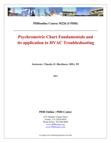
Generator Protection40: Loss of FieldCan adversely effect the generator and the system!! Generator effects Synchronous generator becomes induction Slip induced eddy currents heat rotorsurface High reactive current drawn by generatoroverloads stator Power system effects Loss of reactive support Creates a reactive drain Can trigger system/area voltage collapse115Typical Generator Capability CurveVAROUTNormalWATTVARINLossofFieldGenerator capability curve viewed on the P-Q plane.This info must be converted to the R-X plane.58116
Generator ProtectionGenerator Capability Curve Limiting factors are rotorand stator thermal limits Underexcited limiting factoris stator end iron heatReactive PowerInto SystemRotorWindingLimitedMWMVAROverexcited Excitation control settingcontrol is coordinated withsteady-state stability limit(SSSL)SystemG MVARStatorWindingLimited MWReal PowerInto System0MELUnderexcited Minimum excitation limiter(MEL) prevents exciterfrom reducing the fieldbelow SSSLMW–MVARReactive PowerInto GeneratorSSSLStator EndIron LimitedSystemGMVAR117Generator ProtectionIncreased Power OutP-Q PlaneTRANSFORMATION FROMMW-MVAR TO R-X PLOTIncreased Power OutTYPICAL GENERATORCAPABILITY CURVEExcitation Limiters andSteady State S
- Generator has dedicated unit transformer - Generator has dedicated ground transformer - Likely in large industrial and utility systems - 100% stator ground fault protection available BUS Generator Protection Types of Generator Connections 27 Multiple Bus (High Z), 1