Transcription
“THE NEXT GENERATION”Pressure Relief ValveTechnical ManualBulletin# TECK 596 Rev C 0818“EXPERTS IN SOFT SEAT VALVE TECHNOLOGY”
TABLE OF CONTENTSSECTIONPAGES1.0 Glossary of Pressure Relief Valve Terminology . 32.0 Types of Pressure Relief Valves . 43.0 Flow Safe Enhanced Performance vs.Conventional Lift Characteristics . 54.0 Pop Action and Modulating Action . 65.0 Code Requirements . 76.0 General PRV Installation and PipingRecommendations . 1127.0 Installation Guidelines in Consideration ofDischarge Thrust on PRV’s . 128.0 Pressure Relief Valves and Rupture Disks inSeries . 139.0 Pressure Relief Valve Sizing (Gases & Vapors) . 1410.0 Backpressure Considerations for PRV’s . 1611.0 Pressure Relief Valve Sizing (Liquids) . 1812.0 Thermal Relief Valves . 1913.0 Relief Valve Sizing for Vessel Exposed to Fire . 19
1.0 GLOSSARY OF PRESSURE RELIEF VALVE TERMINOLOGYPRESSURE RELIEF VALVE:SAFETY VALVE:RELIEF VALVE:SAFETY RELIEF VALVE:SET PRESSURE:SIMMER:BLOWDOWN:An engineered device designed to open with a system pressure upset and then close to preventfurther flow of a fluid after normal conditions have been restored.A pressure relief valve actuated by inlet static pressure, characterized by rapid opening or pop action.A pressure relief valve actuated by inlet static pressure, characterized by opening inproportion to inlet pressure increase.A pressure relief valve with opening characteristics of a safety valve or relief valve,depending on application.The measure of opening of a safety relief valve in lb./sq. inch gauge, detectable by sound, sight ortouch. Also defined as opening pressure, popping pressure, pop-off pressure or start-to-dischargepressure.Applied to safety or safety relief valves in compressible fluid service, the audible orvisible fluid escape between seat and spindle at an inlet static pressure below popping pressure andat no measurable capacity.The difference between set pressure and reseat pressure expressed as a percentage of set pressure;i.e., a valve set at 100 psig, reseating at 95 psig has a 5% blowdown.RESEAT PRESSURE:That pressure at which the safety relief valve closes. Most fixed blowdown style safety relief valvesreseat at 30-40% of set pressure, with adjustable blowdown valves reseating at 5-10% of set pressure.OVERPRESSURE:The percentage of pressure applied to an open PRV measured over and above the set pressure.ASME Code Section VIII safety valves must develop full capacity with overpressure of no more than10% or 3 psi, whichever is greater.ACCUMULATION:The pressure increase above maximum allowable working pressure of the vessel during dischargethrough a relief valve expressed as a percentage of that pressure in psig.SUPERIMPOSEDBACKPRESSURE:As transferred back through the discharge system, the static pressure at the outlet of a PRV at thetime the device is required to operate. Also referred to as a secondary pressure source imposed onthe outlet of the PRV.BUILT-UPBACKPRESSURE:Pressure at the outlet caused by flowing forces through that device toward the discharge system.EFFECTIVEDISCHARGE AREA:COEFFICIENTOF DISCHARGE:MEASURED RELIEVINGCAPACITY:COLD DIFFERENTIALTEST PRESSURE (CDTP):CHATTER:Used in flow formulas to determine capacity and is the nominal or computed flow area at the nozzle ofa relief valve.The ratio of the measured relieving capacity of a valve to the theoretical relieving capacity.Expressed gravimetrically or volumetrically, the relieving capacity of a pressure relief device measured at actual flowing pressure and temperature, or at standard conditions.The inlet static pressure at which a relief valve is set to open on the test stand, which includes corrections for service conditions including backpressure and temperature.Abnormal, uncontrolled, rapid reciprocating movement of the spindle (disk) on the seat of a pressurerelief valve.3
2.0 TYPES OF PRESSURE RELIEF VALVES2.1Conventional Pressure Relief Valve:2.3A pressure relief valve incorporating in its design a means ofcompensating for fluctuations due to backpressure.A pressure relief valve utilizing spring force as primarycontrol, directly affected by fluctuations in backpressure,commercially available with fixed or adjustable blowdown. Backpressure affects set pressure on a 1:1 ratio. Balanced against the effects of backpressure. Most balanced pressure relief valves use bellows.These are expensive to purchase and maintain. Self-draining when mounted vertically. Advantageous in handling “dirty” services. Flow Safe F88 Series uses internally balancedspindle(disk) with all PTFE seals. Cost-effective 1/2 NPT—2 NPT. Economical valve selections for typicalnon-lift applications. Commercially available to handle largevariety of temperatures and pressures. Set pressure affected by backpressure ata 1:1 ratio.Balanced Pressure Relief Valve:2.4Pilot Operated Safety Relief Valve (POSRV):A safety relief valve consisting of a main valve assembly and acontrolling pilot valve, combined in one stand-alone unit. Operating characteristics include both snap-action style or modulation style pilots. The main valve seat is held closed or allowedto open by the system pressure itself acting downward on top ofthe piston, as controlled by the pilot. Seat loading decreases as inlet pressureincreases, resulting in simmer before setpressure is reached. Main valve seat loading force increases with inletpressure.42.2 Low profile.“Enhanced Performance”Conventional Pressure Relief Valve: Provides the user with many advantages of accessories, such as field test connections, backflow preventers, inlet filters, manual or auto unloaders and remotepressure pick-up.A pressure relief valve utilizing both spring force as aprimary control and a pressurized spring chamber toachieve enhanced opening, closing, and lift characteristics. This style, like the Flow Safe F84/F85 Series, ischaracterized by immediate full lift at set pressure, maintained until reseat. Modulating pilots provide the operator the ability tooperate close to set point which minimizes processupsets and saves product through their zero blowdowncharacteristic. Can be serviced with main valve in place. Full lift at set point, maintained until reseat. Full flowing performance throughoutrelieving cycle. Self-draining when mounted vertically. Advantageous in handling “dirty” service. Cost-effective 1/4 NPT—2 NPT. Commercially available to handle largevariety of temperatures and pressures. Set pressure affected by superimposedback pressure at a 1:1 ratio.2.5Weight Loaded (Pallet Type) Valve:A valve utilizing weights in lieu of a spring to establish set pressure. These valves are characterized by requiring 100% overpressure to achieve full lift. This style valve is used often incombined service for both pressure and vacuum applications. Set-pressure size-dependent to 15 psig. Commercially available to handle large required flow volumes. Typically, main valve seats tight to 70% of nameplate setpressure. Require extensive overpressure to achieve full lift (100%). Long simmer period before opening. Seat subject tofreezing with cryogenic temperatures and humid atmospheres.
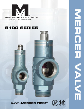
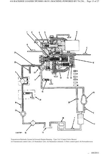
3.0 FLOW SAFE ENHANCED PERFORMANCEVS.CONVENTIONAL LIFT CHARACTERISTICS3.1Flow Safe F84/F85 SRV or SnapAction-Style Pilot Operated SRV’sThe Flow Safe F84/F85 goes into 100% full lift at setpressure. The valve stays at full lift until the reseatpoint. This is the same characteristic of snap-actionPOSRV’S. Value-added allowing user to operate close to valvenameplate set pressure. Provides full capacity relief throughout the flowingcycle. Strong closing force at reseat providing bubble-tightreseating.53.2Conventional SRVTypical conventional style balanced or unbalancedSRV’s crack at approximately 90% of set (simmer) thenadvance to full lift at 100% of set (10% overpressure).These style valves move towards reseat on a similardownward proportion. Because a pressurized springchamber is not incorporated, an inverse relationshipexists between set and blowdown, i.e., the stronger theset, the weaker (longer) blowdown and vice versa. Afixed blowdown valve will not have this interface, but willtypically have long blowdown (30-40%).
4.0 POP ACTION AND MODULATING ACTIONThere are two kinds of valve opening characteristics. They areexplained as follows:4.1Modulating Action:4.2This differs from pop action in that the SRV tends toopen slowly, behaving like a backpressure regulator orcontrol valve. Do not confuse this with direct springoperated relief valves, such as the Flow Safe TypeF84L, which exhibit, at very low flow rate, gradual opening behavior when applied in liquid service.Pop Action (Sometimes called “SnapAction”):This is a rapid opening of the valve. It does not necessarily mean that the valve goes into full lift at setpressure and, in fact, most direct spring operatedSRV’s require overpressure to attain full lift. An exception to this is the Flow Safe F84/F85 series, andF7000/8000 with snap-acting pilot, which do go intofull lift at set pressure. Pop action SRV’s are intendedfor compressible fluids (gases, vapors, and steam).When referring to pop action in the Flow Safe F84/F85or F7000/8000 Series, we mean full opening at set.Because the reseat point of pop action type SRV’s isbelow set pressure, the valve must discharge someamount of gas or vapor in order for pressure to bereduced to the reclosing pressure. This means thatwhen a pop action valve opens due to system pressure upset, it must flow an amount based on the magnitude of the upset plus an additional amount due tosystem volume. For this reason, it is desirable to keepblowdown as short as possible.6CONVENTIONAL SRVF84/F85 ENHANCED PERFORMANCE% BLOWDOWN
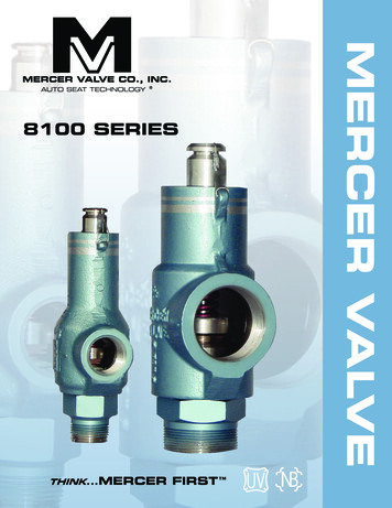
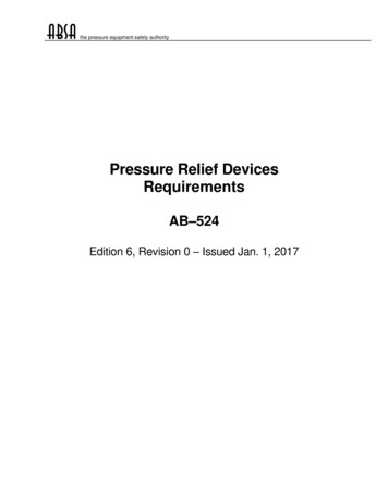
5.0 CODE REQUIREMENTS5.1 BackgroundThe need for valves with an ASME Stamp is driven byregulators, insurance companies, and states or municipalities who adopt the Code and require compliancebefore a building permit or insurance is issued. Woe tothe user whose valve has no stamp and is the unhappytarget of contingency motivated lawyers! Therefore,around the world most applicable valves do bear theASME Stamp. Of course, there are applications like gasdistribution where other codes such as DOT are applicable and ASME is not required. In Europe, PressureEquipment Directive 97/23/EC became mandatory in2002 and has since been superseded by Directive2014/68/EU.5.2 Design and ApplicationsIn Section VIII paragraphs UG-125 thru UG-136, thecode provides users and valve designers guidelines fordesign, material selection, application, and certificationprocedures. Both mandatory rules and non-mandatoryappendices give the user guidance for installation.UG-125 addresses the general need for PRV’s and theirapplication.UG-126(a) Requires that PRV’s be of the direct springloaded type; (b) allows POSRV’s if the main valve flowsfully open should an essential part of the pilot fail.Section UG-126(c) provides set pressure tolerances,while UG-125 (c) and UG-134 describe allowable pressure setting and overpressure limits for pressure reliefvalve installations. Refer to Figures 5.1 and 5.2 for examples of valve settings and basic operational parameters.UG-129 provides specific requirements for nameplates.The nameplate must include the manufacturer and assembler (if applicable), the valve type, size, set pressure,certified capacity, year built or other code to allow fortraceability, and certification mark (ASME Code symbolstamp with UV designator, in the case of ASME Sec.VIII).5.3 Code StampingUG-130 is very important and requires that each valve towhich the code symbol is attached shall have been fabricated or assembled by a manufacturer or assemblerholding a valid certificate of authorization and capacitycertified in accordance with the requirements of thisdivision. This paragraph is your security blanket butsurely does not mean that all valves bearing the ASMEStamp are created or perform equally in all applications.5.4 Valve CertificationUG-131 spells out several methods of capacity certification.For the valve manufacturer all are important but most valvesare certified by the coefficient of discharge (Kd) method.Nine valves are required, three each of three sizes at threeset pressures. In practice, we coordinate selection of thesizes manufactured for certification with the NB to cover thewidest range of sizes and set pressures compatible with thetest facility to be used. Test facilities are rather limited relative to large valves at high pressure. Testing records setpressure, reseat pressure, and capacity at 10% overpressure. Coefficients of discharge Kd (Actual Flow divided byTheoretical Flow) for the nine valves are averaged and allcoefficients must be within /- 5% of the average. Theaverage coefficient Kd is then assigned provisionally to themanufacturer for further confirmation of production valvecapacity per UG-136(c)(3). For capacity calculations, thiscoefficient Kd is multiplied by 0.90 and the coefficient K ofthe design shall not be greater than 0.878 (i.e., the productof 0.9 x 0.975) [(UG-131(e)(2)].5.5 Valve Mechanical CharacteristicsUG-136 addresses minimum requirements for PRV’s andrequires proper guidance for consistent operation, setslimits on spring compression, and further requires that liftlevers be available for steam, air, or water over 140ºF andthey be functional when pressure under the valve is 75% ofset pressure.Other requirements of this paragraph include wrench flatson screwed valves, means for sealing initial adjustmentssuch as set pressure and blowdown, means for draining thedisc, that materials for bodies, bonnets, yokes, and pressure-retaining bolting be listed in Sections II and VIII andthat other materials be listed in Section II, ASTM or becontrolled by the manufacturer.5.6 Production TestingUG-136(c) and (d) define specific requirements for manufacturing, production, testing, and inspection, and mandateperiodic 6-year retesting of production valves. This testingis a check that manufactured valves continue to meet certified capacities.7
Figure 5.1: ASME VIII RELIEF VALVE SETTINGS8NOTE 1 This figure conforms with the requirements of Section VIII of the ASME Boiler and Pressure Vessel Code for MAWPs greaterthan 30 psig.NOTE 2 The pressure conditions shown are for pressure relief valves installed on a pressure vessel.NOTE 3 Allowable set-pressure tolerances will be in accordance with the applicable codes.NOTE 4 The maximum allowable working pressure is equal to or greater than the design pressure for a coincident design temperature.NOTE 5 The operating pressure may be higher or lower than 90%.NOTE 6 Section VIII, Division 1, Appendix M of the ASME Code should be referred to for guidance on blowdown and pressure differentials.Ref: API 520, Part I, 9th Ed., July 2014
5.7 Installation RecommendationsUG-135(b) The pressure drop through the inlet pipingshould not reduce the valve relieving capacity below therequired value or adversely affect pressure relief valveoperation.Appendix M: Inlet piping pressure losses to the pressurerelief valve should not exceed 3%.UG-135(d) The use of intervening block valves betweenthe vessel and the relief device, or between the reliefdevice and point of discharge, is permitted only under thefollowing conditions:5.8Pressure Relief Valve Set Pressurevs. Operating PressureSystem design must consider the differential between theset pressure of the pressure relief valve and the vesseloperating pressure. The blowdown characteristic is essential to proper selection of a compatible valve and operating margin. After a release of pressure, the valve mustbe capable of closing above the normal operating pressure.ASME Section VIII, Div. 1, Appendix M, offers the following recommendations for pressure differential:A. Set pressures up to 70 psig (4.83 barg)A. Block valves are constructed or positively controlled sothat when the maximum number of valves are closedat one time, the relieving capacity provided by theunaffected relieving devices is not reduced below therequired relieving capacity orB. Block valves are set up in accordance with conditionsdescribed in Appendix M:Block valves are allowed for the purpose of inspectionand repair, or other special conditions. The valveshould be a full-area design. It should have a fullround port area and be equal to or greater than thepressure relief valve inlet. The valve should be lockedin the full open position, and should not be closedexcept by an authorized person. When the valve isclosed during any period of the vessel’s operation, anauthorized person should remain stationed at theblock valve.The minimum differential is 5 psi (0.34 bar).B. Set pressures from 71-1000 psig(4.9-69 barg)The minimum differential is 10%.C. Set pressures above 1000 psig (69barg)The minimum differential is 7%.Please note that the user can optimize system pressure by utilizing Flow Safe pressure relief valves, thusbeing able to operate at system pressures greaterthan 90% of set pressure because of premium softseat designs.9
Figure 5.2: ASME CODE SECTION COMPARISON OF PRESSURE RELIEFVALVE REQUIREMENTSCode SectionSet Pressure(psig)Set ECTION IPOWERBOILERSECTION I,CertificationMark“ASME / V”15-70 2 psi2 psi3%71-100 3%2 psi3%101-300 3%2%3%301-1000 10 psi2%3% 1%2%3%2-4 psi5 psi 100015 PSIG STEAM10HEATINGBOILERSECTION IV,CertificationMark“ASME / HV”PRESSUREVESSELSECTION VIII,CertificationMark“ASME / UV”15 2 psiHOT WATER15-60 3 psiNA10%61-160 5%NA10%15-30 2 psiNA3 psi31-70 2 psiNA10% 3%NA10% 70
6.0 GENERAL PRV INSTALLATION AND PIPINGRECOMMENDATIONSA pressure relief valve is installed to protect the user’spersonnel and equipment. Installing a pressure reliefvalve without regard for the surrounding piping doesnot necessarily mean the above has been accomplished.G. Make sure discharge piping is vented or drained toavoid moisture build-up at outlet. Water may freezeat lower temperatures.H. If two or more PRV’s are utilized for capacity requirements, set the first PRV at no more thanMAWP and stagger the remaining at a set pressure5% higher (also see Fig. 5.1). This allows for conservation of product in the event of a minor overpressure occurrence and minimizes interaction.The PRV must be properly sized and selected for theintended application and installed properly.The following provides some guidelines:I. Mount PRV’s in the vertical position whenever possible. Both API 520 and ASME VIII suggest thatthe valve be installed vertically.A. Make sure inlet and discharge piping is largeenough! If piping is too small, either inlet pressureloss and/or built up backpressure will cause thePRV to chatter or cycle excessively and will reduce purchased capacity. ASME Section VIIIrecommends no more than a 3% pressure dropbetween the vessel being protected and the PRV.J. Make sure PRV’s are properly braced to protectagainst discharge thrust.K. Avoid the use of reducing flanges at PRV inlet andoutlets. If possible, use concentric reducers. If notpossible, increase piping diameter.L. The valve orifice should never be larger than theinlet piping. Otherwise, the flow capacity is controlled by the pipe bore, not the relief valve orificeas it should be.POORFAVORABLEB. Keep PRV’s as close to the pressure source aspossible. Avoid long lengths of piping and elbows.Note: An elbow is equivalent to a L/D of 8 orhigher in terms of frictional losses.C. Make sure PRV is not oversized. An oversizedvalve is the same as undersized inlet piping—Youmay have a chatter problem. An oversized valvewastes money and will cycle more frequently.D. Avoid incorrect flange gaskets at PRV inlet oroutlet. They may create a restriction.E. If using block valves, use a full-bore device with alocking mechanism. Also see Section 5.7.F. When redundant PRV’s are used (one for backup), avoid tees. If possible, use individual inlets ora selector valve designed for twin PRV installations.SUMMARY1.2.3.4.Keep piping large.Avoid long runs of pipe.Minimize the number of turns.Minimize inlet loss at pipe junctions by use of reducersor special fittings.Remember, if you must use piping with turns and longruns, keep piping large, especially at PRV inlets, tominimize pressure drop.11
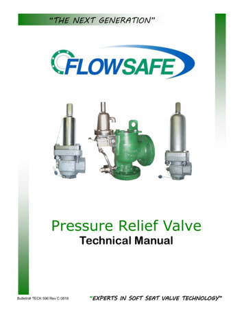
7.0 INSTALLATION GUIDELINES IN CONSIDERATION OFDISCHARGE THRUST ON PRV’S7.1 Piping to and from PRV’s is critical to the proper functioningof the PRV and safety of the installation. When possible,keep PRV located as close to the vessel or pipeline as possible. A long inlet run of pipe may require pipe bracing, especially if handling high pressure. A PRV exhausting at a directright angle will provide for a worst-case bending stress at thevalve inlet.The API RP 520 formula for reaction force (for vertical discharge of gases and vapors):F W366 kT(k 1)M (AP)A non-scientific but approximate calculation:Exhaust Thrust Set Pressure x Orifice AreaWhere:F Reaction force at the point of discharge to theatmosphere, lbf7.2Some concepts to minimize inlet bending stress at PRV inletsusing tail pipe configurations and/or bracing are shown below.(Note: An outlet tee may cause unacceptably high backpressure.)7.3Pressure relief valves that relieve under steady-state flowconditions into a closed system usually do not create largeforces and bending moments on the exhaust system. Only atpoints of sudden expansion will there be any significant reaction forces to be calculated. Closed-discharge systems, however, do not lend themselves to simplified analytic techniques.A complex time-history analysis of the piping system may berequired to obtain the true values of the reaction forces andassociated moments.W Flow of any gas or vapor, lbm/hrk12 Ratio of specific heats (Cp/Cv) at the outletconditionsCp Specific heat at constant pressureCv Specific heat at constant volumeT Temperature at the outlet, oRM Molecular weight of the process fluidA Area of the outlet at the point of discharge, in2P Static pressure within the outlet at the point ofdischarge, psigMETHODS TO MINIMIZE THE EFFECT OF VALVE THRUST
8.0 PRESSURE RELIEF VALVES AND RUPTURE DISKS IN SERIESOftentimes when sealing with corrosive conditionsand/or fugitive emissions, PRV’s are used in conjunction with rupture disks. When used together,and pressure higher than atmospheric(superimposed back pressure) between devices cancause the rupture disk not to fail at the appropriatepressure. For example, if both rupture disks andPRV’s are set at 100 psig with backpressure of 10psig, the disk won’t fail until the system pressurereaches 110 psig.The following are guidelines with reference to ASMESection VIII, Division 1:UG-127(a)(3), to be considered when using a rupture disk at the PRV inlet.1. The relief valve capacity must be derated by10%, or the combination of relief valve and rupture disk must be capacity-certified per ASME VIIIUG-132.2. The rupture disk and relief valve combinationmust deliver adequate capacity per code requirements.3. A free vent or excess flow valve with a pressuregauge or telltale indicator must be installed tosense/relieve backpressure (see diagram).13For discharge (PRV outlet side), rupture disk mayalso be used for corrosive protection. In general, theburst pressure on this rupture disk should be as lowas possible. The space between the PRV and diskmust be vented if operation of the PRV may beaffected. Also, downstream piping should not beobstructed by the disk or fragments. If the PRV isexhausting into a common discharge header, however, the disk should be selected accordingly.www.flowsafe.com
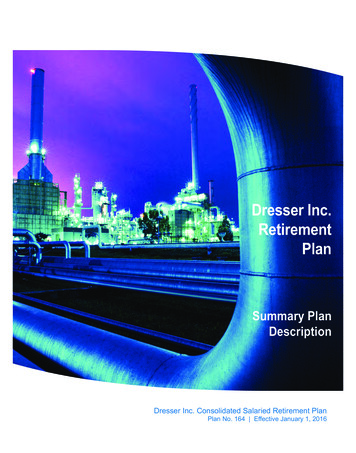
9.0 PRESSURE RELIEF VALVE SIZING (GASES & VAPORS)Ref.: API 520, Part I, 9th Ed., July 2014Described below are criteria and equations used to calculate the flow capacities of pressure relief valves on gas orvapor. Equations are based on API 520 Part I. Capacities for air and natural gas at various set pressures are tabulated on Page 17 for easy reference.To size a relief valve for gas or vapor service, the following information is required: Required flow capacity Required set pressure Backpressure (pressure at valve outlet) Acceptable overpressure [10% or 3 psi per ASME Sec. VIII, or 5% per DOT installation practices] Operating pressure, to assure that it is below valve reseat pressure Gas properties, including molecular weight, specific heat ratio or gas constant, and compressibility factorTo select the required orifice size for a gas or vaporapplication, the below equations should be used. Depending onthe gas, critical flow generally exists at pressures above 11 to 12psig with zero backpressure, or at higher pressures where backpressure is less than approximately 50% of inlet pressure. If backpressure is less than or equal to Pcf in the following equation, critical flow will occur:14Pcf P1Critical Flow[2k 1]kk-1In US customary units:A In SI units:V MTZ dP1KbKc6.32CKA 2.676V MTZCKdP1 KbKc- OR A - OR -WCKdP1KbKc TZMA WCKdP1KbKc TZMSubcritical FlowIn US customary units:V4645F2KdKcA - OR -A W735F2KdKcIn SI units: MTZP1(P1-P2)TZMP1(P1-P2)A 47.95VF2KdKc- OR A 17.9WF2KdKc MTZP1(P1-P2)TZMP1(P1-P2)A VWKdC P1 P2PaKb Kc M T Z F2 kPcf Required discharge orifice area, in2 ormm2Required flow rate, scfm or Nm3/minRequired flow rate, lb/hr or kg/hrCertified (derated) discharge coefficientGas constant, dependent on specific heatratio k Cp/Cv (See Fig. 9.1)Relieving pressure (set pressure plusoverpressure plus atmospheric pressure),psia or kPaaBackpressure, psia or kPaaInlet pressure accumulation, psigBackpressure correction factor, forbalanced bellows valves only(otherwise, use 1.0)Rupture disk correction factor:1.0 with no disk0.9 with disk in combinationMolecular weight at inlet relievingConditions (See Fig. 9.1)Relieving temperature, R ( F 460) or K ( C 273)Compressibility factor at inlet relievingconditions, 1.0 if unknownCoefficient of subcritical flow(See Fig. 9.2)Specific heat ratio, Cp/Cv (See Fig. 9.1)Critical flow nozzle pressure
Figure 9.1: Molecular Weights and Gas Constants for Various Gases & Gas Constants as a Function of SpecificHeat RatioGasMol.Wt.Cp/CvC (US)C 23290.0250Carbon Disulfide761.213380.0257Carbon Dioxide441.293460.0263Carbon ohexane841.083250.0246Ethylene281.243410.0259Freon 220.0245Hydrochloric n hane161.313480.0264Methyl Alcohol321.203370.0256Methyl tural Gas 300.0251Sulphur Dioxide641.273440.0261Specific Heat Ratio(Cp/Cv)C (US)C (SI)Specific Heat Ratio(Cp/Cv)C (US))C 03041.503650.027715
Figure 9.2: Values of F2 for Subcritical Flow (for equations on p. 14)10.0 BACKPRESSURE CONSIDERATIONS FOR PRV’S1610.1General DiscussionWhen backpressure exists in the outlet of a relief valve,caused by either superimposed or built-up pressure during a discharge, the effects on set pressure and backflowmust also be considered. See the glossary for the definitions of superimposed and built-up backpressure.If the relief valve is unbalanced, superimposed backpressure will increase the set pressure on a one-to-one psigratio. Built-up backpressure will not affect the set pressure. For example, a relief valve set at 150 psig with 43psig superimposed backpressure will lift at 193 psig(ASME nameplate requirements provide for set pressurecorrection due to backpressure).All discharge flanges and associated piping and fittings must be ableto withstand these backpressures and the associated loads (forcesand moments).To roughly estimate the built-up backpressure (P2), multiply the ratioof the inlet area (A1) / outlet area (A2) times the inlet pressure (P1):P2 P1 x A1 / A2. See example below.This is a very rough estimate and does not take into account thespecific fluid properties at pressure, or pressure losses due to thedischarge piping arrangement. It is also less accurate at higher pressures. See Sec. 10.2 for a more detailed method for determiningbackpressure.Also, on some manufacturer’s valves (not Flow Safe’sF7000 Series), excessive backpressure may cause thevalve to partially close, further reducing the capacity. Thisis particularly true on bellows-style valves.Example: Backpressure at valve outletBackpressure in excess of the inlet system pressure maycause the valve to open unless there are design featuresin the valve that can compensate for this, i.e., backflowpreventer, split piston, etc.Backpressure (P2)2 x 3 PRV, 2.95 sq.in. nozzle, set
9.0 Pressure Relief Valve Sizing (Gases & Vapors) .14 10.0 Backpressure Considerations for PRV's .16 SECTION PAGES TABLE OF CONTENTS 2 11.0 . operated relief valves, such as the Flow Safe Type F84L, which exhibit, at very low flow rate, gradual open-ing behavior when applied in liquid service.