Transcription
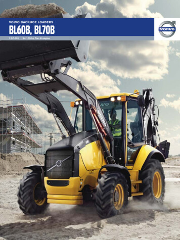
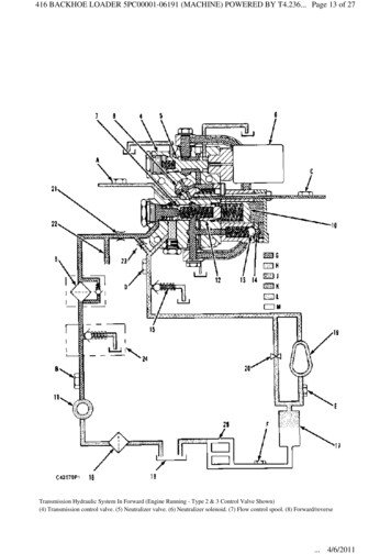
416 BACKHOE LOADER 5PC00001-06191 (MACHINE) POWERED BY T4.236. Page 13 of 27Transmission Hydraulic System In Forward (Engine Running - Type 2 & 3 Control Valve Shown)(4) Transmission control valve. (5) Neutralizer valve. (6) Neutralizer solenoid. (7) Flow control spool. (8) Forward/reverse. 4/6/2011
416 BACKHOE LOADER 5PC00001-06191 (MACHINE) POWERED BY T4.236. Page 14 of 27selector valve. (9) Oil filter. (10) Load piston. (11) Oil pump. (12) Relief valve. (13) Check valve for load piston. (14) Orifice forload piston. (15) Inlet relief valve for torque converter. (16) Screen. (17) Oil cooler. (18) Oil reservoir. (19) Torque converter. (20)Orifice for torque converter bypass. (21) Orfice. (22) Supply passage to 4-WD clutches. (23) Orfice. (24) Relief valve (4-WDonly). (25) Transmission lubrication system. (A) Pressure tap for reverse clutch. (B) Pressure tap for pump. (C) Pressure tap forforward clutch. (D) Pressure tap for torque converter inlet. (E) Pressure tap for torque converter outlet. (F) Pressure tap forlubrication and cooling. (G) Pump oil. (H) Return oil. (J) Converter inlet oil. (K) Supply oil. (L) Converter outlet oil. (M)Lubrication oil.The basic components of the hydraulic system for operation of the transmission and torque converter are: oilreservoir (18), oil screen (16), oil pump (11), oil filter (9), torque converter (19), flow control spool (7),relief valve (12), load piston (10) for shift modulation, check valve (13) for load piston, forward/reverseselector valve (8), neutralizer valve (5), neutralizer solenoid (6), relief valve (15) for converter inlet, oilcooler (17), forward clutch pack (1) and reverse clutch pack (2).All oil passages are inside the transmission case and transmission control valve (4) body, except the twotransmission hydraulic lines connected to oil cooler (17). From serial number 3DJ1-UP, 5PC4451-UP,7BC1163-UP, 6TC1364-UP and 5KF1-UP, an external tube provides an oil passage from the relief valvepassage to the neutralizer valve passage.Torque Converter, Transmission Pump, Screen And FilterThe oil for the operation, cooling and lubrication of the transmission and torque converter is made availableby an internal gear pump. The pump is located at the transmission input shaft. The torque converter statorsupport and pump are assembled together and the assembly is bolted to the transmission case. The pump isdriven by the torque converter impeller housing.The oil reservoir for the transmission and torque converter is in the bottom of the transmission case. Oilfrom the reservoir flows through the pipe assembly to the screen and through the transmission case passagesto the suction side of the positive displacement pump. The oil from the pump flows to the filter and then thetransmission hydraulic controls. If there is a restriction in the oil filter or if the viscosity of the oil is veryhigh, the bypass valve in the filter housing will open.If the inlet pressure to the oil filter is 117 to 131 kPa (17 to 19 psi) greater than the outlet pressure, thebypass valve will open. When the oil does not go through the filter element, unfiltered oil could causedamage to other components in the hydraulic system.Correct maintenance must be used to make sure that the element does not become plugged and stop the flowof clean oil to the hydraulic system. The filter is mounted to the left side of the transmission case.The screen is mounted inside the transmission case. The screen can be removed on the right side of case.Location Of Oil Filter. 4/6/2011
416 BACKHOE LOADER 5PC00001-06191 (MACHINE) POWERED BY T4.236. Page 15 of 27Location Of Screen (Behind Plug Assembly)Power Train Oil CoolerThe power train oil cooler is mounted in the bottom tank of the radiator.System oil with high temperature comes from the torque converter outlet. This oil goes in one side of thecore assembly. The flow of oil is through the core assembly, as coolant flows around the core assembly. Inthis way, heat is removed from the oil and is given to the coolant.After the oil flows through the cores, it goes out through the outlet passage at the other end of the coreassembly and has a lower temperature. The cooler oil then goes to the transmission lubrication and cooling.Location Of Power Train Oil Cooler. 4/6/2011
416 BACKHOE LOADER 5PC00001-06191 (MACHINE) POWERED BY T4.236. Page 16 of 27Transmission Lubrication SystemTransmission LubricationThe only pressure lubrication in the transmission is for the forward and reverse shuttles, discs, plates andbearings. After the oil has been cooled by the oil cooler, the oil will enter the right side of the transmissioncase and go to the right end of the input shaft. Oil flows down the oil passages in the shaft and cools andlubricates the bearings, plates and discs.The other gears and bearings are splash lubricated. The movement of the gears in the oil reservoir causes oilto be thrown on all components.Hydraulic ControlsNOTE: Serial number breaks for the different types of control valves are:Type 1; 5PC1-5PC4450, 7BC1-7BC1162, and 6TC1-6TC1363.Type 2; 3DJ1-3DJ173, 5PC4451-5PC8078, 7BC1163-7BC2628, 6TC1364-6TC4297 and 5KF1-5KF466.Type 3; 3DJ157-UP, 5PC8079-UP, 7BC2629-UP, 6TC4297-UP and 5KF467-UP.Location Of Transmission Hydraulic Controls. 4/6/2011
416 BACKHOE LOADER 5PC00001-06191 (MACHINE) POWERED BY T4.236. Page 17 of 27The torque converter inlet oil pressure is limited by relief valve (15) mounted in the valve adapter. The valveadapter is mounted between the control valve and the transmission case. The relief valve limits the pressureto the torque converter to 750 kPa (110 psi)The transmission hydraulic controls are installed on top of the transmission case. Inlet oil to operate thehydraulic controls comes from oil filter (9).Flow control spool (7) provides a predetermined maximum flow rate to the transmission circuit andbypasses excess flow to the torque converter circuit. The orifice down the center of the spool provides theoil for the transmission circuit. The flow control spool position will change to maintain needed flow throughthe control valve as load changes.Location Of Neutral/Start SwitchForward/reverse selector valve (8) rotates to direct pressurized oil to the forward or reverse clutch pistons orto drain if in NEUTRAL. The selector valve also allows the clutch pistons to drain if they are not engaged.The selector valve also activates and deactivates the neutral/start switch.If the selector valve is left in a forward or reverse position when the vehicle is turned off, the selector valvewill deactivate the neutral/start switch so the vehicle cannot be started until the selector valve is returned tothe neutral position at next start-up.The forward/reverse selector valve is mechanically actuated by a mechanical linkage and the directioncontrol lever mounted on the steering wheel column.Location Of Direction Control LeverNeutralizer valve (5) and neutralizer solenoid (6) are used when the transmission is to have a speed changeor full horsepower is required at the loader hydraulics.Location Of Neutralizer Button On Shift Lever. 4/6/2011
416 BACKHOE LOADER 5PC00001-06191 (MACHINE) POWERED BY T4.236. Page 18 of 27Location Of Neutralizer Button On Loader LeverThe neutralizer solenoid is controlled by two neutralizer button switches. One switch is located on the gearshift lever and the other on the loader lever. To activate the neutralizer solenoid, the neutralizer buttonswitch would be pushed in and held until the shift is complete or the loader function is complete. The buttonis released to deactivate the neutralizer solenoid.When the neutralizer solenoid is activated a rod extends to the left, moving neutralizer valve (5) to the lefttoo. As the neutralizer valve moves to the left a drain port is opened, allowing most pressurized oil for thetransmission circuit to go to the drain (reservoir). The oil pressure in the directional clutch circuit decreasesand the directional clutch disengages. When the neutralizer solenoid is deactivated the rod retracts and thespring returns the neutralizer valve, closing the drain port, refilling the directional clutches and allowing thetransmission to gain pressure again.Do not operate the engine at high idle speed with cold transmission oil.The cold oil may prevent the neutralizer valve from functioningproperly and the machine could move.The modulating relief valve consists of relief valve (12) and load piston (10). The modulating relief valveprovides a variable relief valve, controls the rate pressure rises in the forward or reverse clutch pack andlimits maximum clutch pressure.Orifice (14), in the cover for load piston (10), controls the rate the load piston engages. Check valve (13)allows the load piston to dump oil rapidly. 4/6/2011
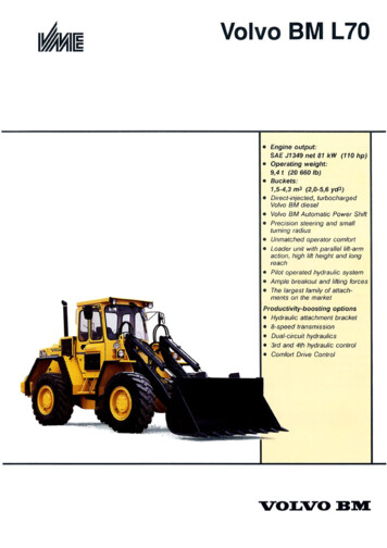
416 BACKHOE LOADER 5PC00001-06191 (MACHINE) POWERED BY T4.236. Page 19 of 27Transmission Hydraulic System In Neutral (Engine Running - Type 1)(1) Forward clutch assembly. (2) Reverse clutch assembly. (3) Input shaft assembly. (4) Transmission control valve. (5)Neutralizer valve. (6) Neutralizer solenoid. (7) Flow control spool. (8) Forward/reverse selector valve. (9) Oil filter. (10) Loadpiston. (11) Oil pump. (12) Relief valve. (13) Check valve for load piston. (14) Orifice for load piston. (15) Inlet relief valve fortorque converter. (16) Screen. (17) Oil cooler. (18) Oil reservoir. (19) Torque converter. (20) Orifice for torque converter bypass.(A) Pressure tap for reverse clutch. (B) Pressure tap for pump. (C) Pressure tap for forward clutch. (D) Pressure tap for torqueconverter inlet. (E) Pressure tap for torque converter outlet. (F) Pressure tap for lubrication and cooling.Operation. 4/6/2011
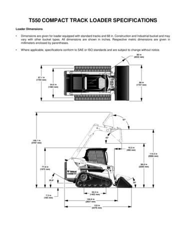
416 BACKHOE LOADER 5PC00001-06191 (MACHINE) POWERED BY T4.236. Page 20 of 27Starting The Engine (Transmission in Neutral)Transmission Hydraulic Control Valve (Type 2)(4) Transmission control valve. (5) Neutralizer valve. (6) Neutralizer valve. (7) Flow control spool. (8) Forward/reverse selectorvalve. (10) Load piston. (12) Relief valve. (13) Check valve for load piston. (14) Orifice for load piston. (23) Orfice. (A) Pressuretap for reverse clutch. (C) Pressure tap for forward clutch. (D) Pressure tap for torque converter inlet. (G) Pump oil. (H) Returnoil. (J) Converter inlet oil.When the engine is started oil pump (11) pulls oil from reservoir (18) through screen (16) to the pump. Thepump sends the oil through filter (9) to control valve (4).Orifice (23) allows oil pump to bleed air to tank during initial start up. Orifice (23) also provide additionaloil flow to the torque converter with out passing through flow control valve (7).Oil pressure moves flow control spool (7) to the right. This allows oil not needed by the transmission circuitto flow to the torque converter circuit.On the machines with type 1 control valves, oil needed by the transmission circuit flows through the orificein the center of flow control (7) spool and goes to forward/reverse selector valve (8).On the type 2 control valve machines, oil needed by the transmission circuit, flows through the orifice in thecenter of flow control spool (7) and goes to the neutralizer valve (5), through the external tube. Then, the oilgoes to the forward/reverse selector valve (8). In NEUTRAL, the selector valve directs oil flow to thereservoir (drain), thus neither forward or reverse clutch pack can be pressurized. The clutch oil passages areopen to drain.Since neutralizer solenoid (6) has not been activated, nothing occurs at neutralizer valve (5). 4/6/2011
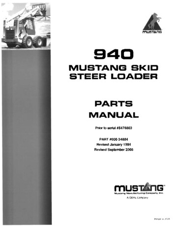
416 BACKHOE LOADER 5PC00001-06191 (MACHINE) POWERED BY T4.236. Page 21 of 27With the forward/reverse selector valve in neutral there is low residual pressure within the control valve. Solittle pressure is sent to load piston (10) for modulation. Relief valve (12) pressure may be as low as initialrelief setting.Transmission Hydraulic Control Valve (Type 3)(4) Transmission control valve. (5) Neutralizer valve. (6) Neutralizer valve. (7) Flow control spool. (8) Forward/reverse selectorvalve. (10) Load piston. (12) Relief valve. (13) Check valve for load piston. (14) Orifice for load piston. (23) Orfice. (A) Pressuretap for reverse clutch. (C) Pressure tap for forward clutch. (D) Pressure tap for torque converter inlet. (G) Pump oil. (H) Returnoil. (J) Converter inlet oil.On the type 3 control valve machines, oil needed by the transmission circuit, flows through the orifice in thecenter of flow control spool (7) and goes to the neutralizer valve (5), through the external tube. Then, the oilgoes to the forward/reverse selector valve (8). In NEUTRAL, the selector valve blocks oil flow, thus neitherforward or reverse clutch pack can be pressurized. The clutch oil passages are open to drain. Sinceneutralizer solenoid (6) has not been activated, nothing occurs at neutralizer valve (5).With the forward/reverse selector valve in neutral there is full oil pressure built up within the control valve.So pressure is sent to load piston (10) for modulation. Relief valve (12) maintains full relief pressure. 4/6/2011
416 BACKHOE LOADER 5PC00001-06191 (MACHINE) POWERED BY T4.236. Page 22 of 27Transmission Hydraulic System In Forward (Engine Running - Type 1)(1) Forward clutch assembly. (2) Reverse clutch assembly. (3) Input shaft assembly. (4) Transmission control valve. (5)Neutralizer valve. (6) Neutralizer solenoid. (7) Flow control spool. (8) Forward/reverse selector valve. (9) Oil filter. (10) Loadpiston. (11) Oil pump. (12) Relief valve. (13) Check valve for load piston. (14) Orifice for load piston. (15) Inlet relief valve fortorque converter. (16) Screen. (17) Oil cooler. (18) Oil reservoir. (19) Torque converter. (20) Orifice for torque converter bypass.(A) Pressure tap for reverse clutch. (B) Pressure tap for pump. (C) Pressure tap for forward clutch. (D) Pressure tap for torqueconverter inlet. (E) Pressure tap for torque converter outlet. (F) Pressure tap
07.04.2011 · 416 BACKHOE LOADER 5PC00001-06191 (MACHINE) POWERED BY T4.236. Page 20 of 27. 4/6/2011. With the forward/reverse selector valve in neutral there is low residual pressure within the control valve. So little pressure is sent to load piston (10) for modulation. Relief valve (12) pressure may be as low as initial relief setting. Transmission Hydraulic Control Valve (Type 3) (4) Transmission .