Transcription
Model 750EBrake ActuatorOwner’s Manual
Installation Instructions and Service ManualModel 750E - 7,500 lbs. CapacityPart #70521 Disc BrakePart #70522 Drum BrakeModel 750 - 7,500 lbs. CapacityPart #70501 Disc BrakePart #70502 Drum BrakeModel 7007,000 lbs. CapacityPart #70464 Disc BrakePart #70465 Drum BrakeTable of ContentsActuator Installation InstructionsHitching the TrailerVehicle Wiring - Free Backing Brake SolenoidActuator MaintenanceWarningsBleeding InstructionsPart Diagrams and Replacement PartsLimited WarrantyPage23-4445-67-89-1213-14TIE DOWN ENGINEERING255 Villanova Drive SW, Atlanta, GA 30336(404) 344-0000 Fax (404) 349-0401 2014 TIE DOWN Inc., ALL RIGHTS RESERVED
IMPORTANT: READ AND UNDERSTAND THE ENTIRE INSTRUCTION/ASSEMBLYPROCEDURE BEFORE INSTALLING YOUR BRAKES AND ACTUATOR.The Model 750E works by the “surge” or “push” of the trailer toward the tow vehicle.This automatically synchronizes the trailer brakes with the tow vehicle axle brakes. Whenthe trailer pushes against the tow vehicle, the actuator telescopes together and appliesthe force to the master cylinder, supplying hydraulic pressure to the brakes. The built indampening shock absorber retards the telescoping shock against the hitch ball.Be sure to comply with regulations for brakes in your state. Brake laws sometimes areminimum standards and you may wish to add additional brakes to your trailer.Read your tow vehicles owner’s manual on towing capacity and other towingrecommendations before installing brakes or this actuator. The Model 750E Actuator iscompletely assembled and ready to bolt into place, if not all ready installed. Manufacturedfor tongue sizes: 3”x 3”, 3”x 4” & 3”x 5”.1.Bolt the actuator to the tongue-using grade 5 bolts 1/2 inch in diameter, 4 incheslong. Lightweight tongues, less than 11 gauge, require spacer tubes inside thetongue for reinforcement. Attachment strength should equal or exceed than1-1/2 times trailer G.V.W.R.2.Hydraulic brake lines should be installed on the trailer as described in theinstallation manual supplied with the brakes. Note: Some disc brakes require theuse of flexible brake lines at the connection POINT on the brake caliper. Followbrake manufacturer instructions.3.Use only DOT-3 heavy-duty brake fluid in the Model 750E actuator. Use a pressuretype brake bleeder to bleed brakes. (This type of brake bleeder is available at yourlocal automotive jobber.) Follow manufacturer’s directions. Or, manually bleed thebrakes using a heavy-duty flat blade screwdriver inserted in the hole provided ontop of the actuator near the front. Insert the screwdriver and use a pumping actionto activate the master cylinder in order to bleed the brakes.See page 7 for more details.To bleed master cylinder and brakes, install bleeder hose on first wheel cylinder tobe bled; if tandem axle trailer, bleed closest axle first, and the closest brake on thataxle first. Use a loose end of hose from the bleeder valve submerged in a glasscontainer of brake fluid to observe bubbling (hose must be submerged into cleanbrake fluid to keep air from traveling back into the brake cylinder). Loosen thebleeder screw located in the wheel cylinder one turn, the system is now open to theatmosphere. The bleeding operation for that brake is complete when bubbling stops.Be sure to tighten bleeder screw securely.Each wheel cylinder must be bleed until all air is out of the lines. Replenish thebrake fluid during the bleeding process so the level does not fall below half full levelin the master cylinder reservoir. When bleeding and testing is completed, make suremaster cylinder is filled to 3/8” below the top of the reservoir and filler cap issecurely in place.Page 2
4. Check with your state motor vehicle department for laws concerning minimumtrailer brake requirements. Some states may require brakes on all axles.5. Road test trailer a short distance to activate the actuator several times. Check fluidlevel again. Remember, low brake fluid levels will result in hitch ball knocking.6. When testing is completed, make sure master cylinder is filled to 3/8” below the topof the reservoir and filler cap is securely in place. Road test again to make surebrakes work properly.RATED CAPACITY: Maximum Actuator Capacity: 7500 lbs. (Model 700-7000 lbs.)Gross Load, 750 lbs. Maximum Tongue Load (Model 700-700 lbs.)The actual in-service rating is limited to that of the ball and hitch being used or thetrailer manufacturer’s G.V.W.R. shown on the certification label, whichever is lower(Note: G.V.W.R. is the Gross Vehicle Weight Rating which includes the trailer and the loadweight as a Total Gross Weight).Hitching The Trailer1. The vehicle, towing hitch and ball must have a rating equal to or greater thantrailer G.V.W.R.2.Model 750E will accept 2” or 50mm trailer hitch balls only. Trailer balls larger than2.00” (50mm) or out of round will not fit the coupler or may result in couplerfailure. Balls smaller than 1.95” can cause shock loading and suddendisconnection. Make certain ball latch is in correct position to retain the hitch ball.Push latch until safety latch engages plate below latch. Insert safety pin into forwardhole as a safety lock for the hitch ball coupler prior to towing. Do not tow trailer ifcoupler is damaged.3. Connect safety cables or chains using crossed pattern under tongue, or followtrailer manufacturer’s directions.4. Connect actuator breakaway cable S-hook to the tow vehicle only. Do notconnect S-hook to the safety cables or chains.5. The breakaway system is designed to only operate after the trailer detaches fromthe tow vehicle and the safety chains have failed. The breakaway is not a parkingbrake. Do not use as such.6. If the breakaway is accidentally applied, insert a flat bladed screwdriver into thespring clip on the side of the actuator and pry sideways pressure to release,see page 8.7. Any control devices that restrict operation of the actuator cannot be used. Thisincludes certain sway control devices. The actuator must be free to telescope inresponse to braking requirements.8. Equalizing or weight distributing hitches may be used, that are designed to use withsurge brake actuators, allow six to eight inches free chain length.Page 3
DANGER: Tongue weight beyond rating limits will interfere with performance ofactuator, and braking system, and the tow vehicle.9. The actuator is designed for use with Free-Backing trailer brakes. To blockbraking action, (in order to back up) with other types of brakes including discbrakes, use an electric solenoid. For trailer movement when brakes are not required,place the safety pin in the hole on the side of the actuator housing to blockmovement of the actuator.DANGER: Failure to remove pin will also prevent forward braking. Pin mustbe in the lower, forward hole as a safety lock for the hitch ball coupler latchwhen towing at all times.Directions Vehicle Wiring - Brake Solenoid1. Disconnect trailer hitch and any wiring connectors from the vehicle.2.Connect a 14 gauge wire to the backup (reverse) light wire of the vehicle. Thiswire should be of sufficient length to attach to the existing vehicle/trailerwire receptacle. The end of this wire will require a female end that will match thesolenoid male connector wire. Your vehicle may have a 5 wire connection forthis purpose.3. For ease of use, tape or band the end of the reverse light wire to the vehicle’strailer electrical connector.Maintenance1. Always check the brake fluid reservoir before using trailer. Make sure it is at leasthalf full. If not, re-fill to 3/8 inch below the top of the reservoir with DOT 3 brakefluid. Do not use DOT 5 brake fluid. Check for leaks and repair as required.Never reuse brake fluid.2. To extend coupler and ball life, coat both with a thin coating of grease. This will alsoeliminate squeaking. Wipe clean and renew film each time trailer is used.3. Examine the actuator for bent parts or wear each time the trailer is used.Replace parts as necessary.4. There are no user adjustments on the actuator.5.Actuator travel (shown by coupler roller path) over one inch indicates a need toadjust the brakes or add fluid to the reservoir or a need to bleed the brakes andcheck connections for leaks. Adjust per instructions found in brake installationmanual. In general, back-off adjusters on drum brakes from locked position, asrequired. Adjust Free-Backing brakes by rotating in forward direction only. Failureto adjust may result in loss of braking. Disc brakes do not require adjustment,check for pad wear.Page 4
Braking and Trailering WarningsWARNINGActuator and brakes should always be flushed with fresh water after using trailer incorrosive conditions. This includes salt water, fertilizers and other corrosive materials.Before storing trailer remove brakes and clean thoroughly. It is also wise to repack thebearings at the same time. Failure to properly and adequately maintain the actuatorcould cause serious damage, injury or death.WARNINGThe breakaway system is not designed to operate if the trailer does not separatecompletely from the tow vehicle, or if the tongue goes under the rear of the tow vehicle.WARNINGIn the event that the breakaway system is used, check all system components (cable,S-hooks, etc.) for proper working order. Replace any damaged parts with genuine TieDown parts only.WARNINGWhen re-setting the break a way system keep hands and fingers clear as you re-set themechanism, hydraulic pressure held in the system may cause the assembly to snap backsuddenly.WARNINGAVOID sharp turns, which can cause the actuator to bind or jackknife against the towvehicle or cause a bend in the tongue. Either can damage the actuator causing brakefailure. AVOID towing trailer across large bumps or dips that may over stress theconnection between the trailer and tow vehicle, as this could result in damage tothe actuator.WARNINGDO NOT REUSE BRAKE FLUID. Always use fresh DOT 3 fluid from a fresh container. Failureto maintain proper levels of fluid in the reservoir will cause brake failure.WARNINGFailure to install the hitch pin before towing can result in accidental opening of the couplerhitch latch which can lead to the trailer coming off of the hitch ball causing seriousdamage, injury or death. If pin will not fit into the front lower hole, the coupler is notattached properly. Re-set coupler on hitch ball.Page 5
WARNINGA minimum of 5% tongue weight and a maximum 10% tongue weight of the trailerG.V.W.R. must be located on the hitch ball. The Trailer tongue should be parallel to theground. Too much weight can cause premature brake actuation and loss of control of thetowing vehicle. To little tongue weight can cause the trailer to fishtail, resulting in loss ofcontrol of the tow vehicle and trailer (total trailer weight G.V.W.R. includes weight of thetrailer plus load).WARNINGA loose fit between the coupler and hitch ball can cause the actuator and hitch ball toseparate, causing serious damage, injury or death. Check coupler every time prior totowing and at each stop on long trips. Always make certain that coupler latch safetypin is securely installed into coupler latch.WARNINGBrake laws sometimes are minimum standards and you may wish to add additionalbrakes to your trailer. Read your tow vehicles owner’s manual on towing capacity andother towing recommendations before installing brakes or this actuator.WARNINGNever allow the coupler latch safety pin to remain in the reverse lockout position hole.After reverse maneuvering, always insert coupler latch safety pin back into couplerlatch. FAILURE TO REMOVE SAFETY PIN FROM REVERSE LOCK OUT POSITION HOLEWILL PREVENT FORWARD MOVEMENT BREAKING WHICH CAN RESULT IN SERIOUSPROPERTY DAMAGE, INJURY OR DEATH.WARNINGTie Down actuators and brakes are designed to use DOT 3 (or 4) brake fluid.Do not use of DOT 5 brake fluid. Use of DOT 5 brake fluid will cause damage to internalparts that can result in loss of brake power.Page 6
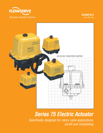
Bleeding InstructionsTo bleed master cylinder and brakes, install bleeder hose on first wheel cylinder to bebled; if tandem axle trailer, bleed closest axle first, and the closest brake on that axlefirst. Use a loose end of hose from the bleeder valve submerged in a glass containerof brake fluid to observe bubbling (hose must be submerged into clean brake fluid tokeep air from traveling back into the brake cylinder). Loosen the bleeder screwlocated in the wheel cylinder one turn, the system is now open to the atmosphere.To pump master cylinder, insert a flat tipscrewdriver into the bleeding access port ontop, near the front of the actuator cover(See right photo and 1A below).BleedingAccess PortThe screwdriver should be at the lowest anglepossible to the actuator so that it slides infront of the e-stop bracket (See 1B).FRONTFRONTScrewdriver tip MUST BE IN FRONT of thee-stop bracket and NOT in the slot on thee-stop bracket (See 2A).FRONTPage 7FRONFRONT
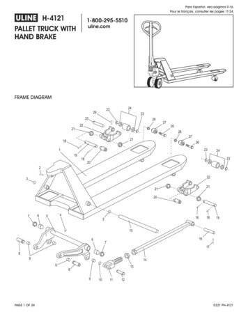
FRONTFRONTPush the screwdriver forward and back topump the master cylinder. (See 2B).The bleeding operation for that brake iscomplete when bubbling stops. Be sure totighten bleeder screw securely. Each wheelcylinder must be bleed until all air is out ofthe lines. Replenish the brake fluid during thebleeding process so the level does not fallbelow half full level in the master cylinderreservoir.When bleeding and testing is completed, makesure master cylinder is filled to 3/8” below thetop of the reservoir and filler cap is securelyin place.Emergency Button StopEmergencyButton StopShown in normaloperating positionWARNING: If button stopcable is showingDO NOT TOW TRAILERRelease emergency stopcable by prying spring outwith a flat blade screwdriver.Page 8
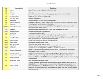
Model 750E/750/700 Parts DiagramModel 750E - 7,500 lbs. CapacityPart #70521 Disc BrakePart #70522 Drum Brake1&6Model 750 - 7,500 lbs. CapacityPart #70501 Disc BrakePart #70502 Drum BrakeModel 7007,000 lbs. CapacityPart #70464 Disc BrakePart #70465 Drum Brake51753541A112Page 9
Model 750E/750/
Be sure to comply with regulations for brakes in your state. Brake laws sometimes are minimum standards and you may wish to add additional brakes to your trailer. Read your tow vehicles owner’s manual on towing capacity and other towing recommendations before installing brakes or this actuator. The Model 750E Actuator is completely assembled and ready to bolt into place, if not all ready .