Transcription
User's GuideSLUUBA9 – June 2015Using the TPS53647: PWR710-EVM, 4-Phase, D-CAP Step-Down, DC-DC Analog with PMBus InterfaceThe PWR710-EVM evaluation module (EVM) uses the TPS53647 controller. The controller is 4-phase, DCAP synchronous buck driverless controllers PMBus interface. The device operates using a voltagesupply between 4.5 V and 17 V. The controller allows programming and monitoring via the PMBusinterface. This PWR710-EVM uses the CSD95372B, Synchronous Buck NexFET Smart Power Stage(SLPS499) device as the power stage.1DescriptionThe PWR710-EVM operates as a single output converter. The nominal 12-V bus produced a regulated,1.0-V output at up to 120 A of load current. The PWR710-EVM demonstrates the controller in a typicallow-voltage high-current application while providing a number of test points to evaluate the performance ofthe controller. Refer to TPS53647 (SLUSC39) datasheet for more information on multi-phaseconfiguration.1.1Typical Applications 1.2ASIC power in communication equipmentHigh density power solutionsServer powerSmart power systemsFeatures Regulated 1.0-V output up to 120-A DC steady state output currentOutput can be marginable and trimmable via the PMBus interfaceProgrammable through PMBus interface– UVLO protection threshold– Soft-start slew-rate– Device enable and disable– Overcurrent warning and fault limits– SW frequency– BOOT voltageProgrammable high- and low-output margin voltages with a maximum rangeConvenient test points for probing critical waveformsSLUUBA9 – June 2015Submit Documentation FeedbackUsing the TPS53647: PWR710-EVM, 4-Phase, D-CAP Step-Down, DC-DCAnalog with PMBus InterfaceCopyright 2015, Texas Instruments Incorporated1
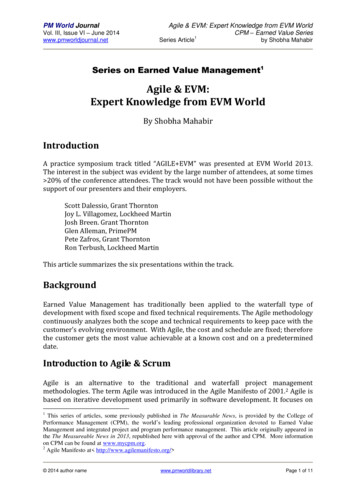
Electrical Performance Specifications2www.ti.comElectrical Performance SpecificationsTable 1. PWR710-EVM Electrical Performance SpecificationsPARAMETERTEST CONDITIONSMINTYPMAX81214UNITSINPUT CHARACTERISTICSVINVoltage rangeVIIN(max)Maximum input currentVIN 8 V, IOUT 120 A12ANo load input currentVIN 14 V, IOUT 0 A120mAOUTPUT CHARACTERISTICSVOUTOutput voltageIOUTOutput load current1.0V0120Output voltage line regulation8 V VIN 14 V0.03%Output voltage load regulation0 A IOUT 120 A0.03%VRIPPLEOutput voltage rippleVIN 12 V, IOUT 120 AVOCPOutput overcurrent protection(OCP)A3.8mVpp150A500kHzSYSTEMS CHARACTERISTICSfSW3Switching frequencyVIN 12 VVOUTPeak efficiencyVIN 12 V, IOUT 74 A, fSW xxxkHz91%VOUTFull-load efficiencyVIN 12 V, IOUT 120 A90%Operating 54.7µFU11 8V LDOTP6V3R35V CONR6 1.00VIN CV3R3R82.00kTP10ENABLERESET#J5PMB CLKPMB ALERT#PMB 19.31kR1316.5kR1216.5kADDR kR2439.2kR25150kR1924.3kC240.33µF TP7TP85V CONCSP1CSP2CSP3CSP45V CONV12V3R3151614ENABLE23RESET#21PMB CLKPMB ALERT#PMB DIO242526TSEN40VSPVSN910CSP1CSP2CSP3CSP43456ADDR 4.3kAGNDTPS53647RHAV5V12V3R3VREFISUMENABLERESETPMB CLKPMB ALERTPMB DIOIMONCOMPPWM1PWM2PWM3PWM413VREFVREF12ISUMISUM TP92IMON11COMP38373635PWM1PWM2PWM3PWM4182719VR RDYVR FAULT#VR HOT#39SKIP# M41000pFC2812pFTSENVSPVSNVR RDYVR FAULTVR HOTCSP1CSP2CSP3CSP4SKIP NVMADDR NDGNDPADVR RDYVR FAULT#VR HOT#SKIP# NVM78333417202241PWRGND0AGNDPWRGNDFigure 1. PWR710-EVM Schematic2Using the TPS53647: PWR710-EVM, 4-Phase, D-CAP Step-Down, DC-DCAnalog with PMBus InterfaceCopyright 2015, Texas Instruments IncorporatedSLUUBA9 – June 2015Submit Documentation Feedback
Schematicwww.ti.comTP1J1Vin: 8-14VdcJ4L1VIN13579VINVIN CC122µFTP2J2246810PMB ALERT#PMB DIOC222µFPMB CLKGNDFigure 2.Figure 3.J61 8V LDO1233 3V LDOV3R3R1710.0kTP12R2310.0kP ALERT#PMB ALERT#VR HOT#VR FAULT#VR RDYTP14TP17VR FAULT#VR RDYC300.1µFTP13R2210.0kTP16TP15R1810.0kP CLKPMB CLKR2610.0kR1610.0kP DIOVR HOT#PMB DIOFigure 4.VIN e 5.SLUUBA9 – June 2015Submit Documentation FeedbackUsing the TPS53647: PWR710-EVM, 4-Phase, D-CAP Step-Down, DC-DCAnalog with PMBus InterfaceCopyright 2015, Texas Instruments Incorporated3
KIP# NVMR2 150k24R3 igure 6.U2C31TP187VIN CPWM112PWM1R39SKIP# NVM10VINBOOTPWMBOOT RFCCM0TAO/FAULTR295V DRV51.00R31V3R33VSWR35CSP110TAO0.1µFR33 0kC33 NPVDD9C43DNPC391000pFC44470µFR431.00VREFFigure 7. Phase 1U3C32TP197VIN CPWM212PWM2R40SKIP# NVM10VINBOOTPWMBOOT RFCCM05V FR34 0kC34 2DNPR38DNPCSD95372BQ5MC361000pFR441.00VREFFigure 8. Phase 24Using the TPS53647: PWR710-EVM, 4-Phase, D-CAP Step-Down, DC-DCAnalog with PMBus InterfaceCopyright 2015, Texas Instruments IncorporatedSLUUBA9 – June 2015Submit Documentation Feedback
Schematicwww.ti.comU4TP20C497VIN CPWM312PWM3R5510SKIP# NVMVINBOOTPWMBOOT RFCCM0TAO/FAULTR455V DRV1.00R47V3R35VDD3R511CSP3TAO0.1µFR49 .0kC51 VREFFigure 9. Phase 3U3C32TP197VIN CPWM212PWM2R40SKIP# NVM10VINBOOTPWMBOOT RFCCM05V FR34 0kC34 2DNPR38DNPCSD95372BQ5MC361000pFR441.00VREFFigure 10. Phase 4SLUUBA9 – June 2015Submit Documentation FeedbackUsing the TPS53647: PWR710-EVM, 4-Phase, D-CAP Step-Down, DC-DCAnalog with PMBus InterfaceCopyright 2015, Texas Instruments Incorporated5
Test Setupwww.ti.com4Test Setup4.1Test and Configuration SoftwareUse the TI Fusion Digital Power Designer software to change any of the default configuration parameterson the EVM. To download this software, visit the Digital Power Software page.4.1.1DescriptionFusion Digital Power Designer is the graphic user interface (GUI) used to configure and monitor controlleron this EVM. The software uses the PMBus protocol to communicate with the controller over serial bus byway of a TI USB adapter (see Figure 12).4.1.2TI Fusion Digital Power Designer FeaturesThe software offers these features: Turn on or off the power supply output, either through the hardware control line or the PMBusoperation command. Monitor real-time data. Items such as output voltage, output current, temperature, warnings and faultswhich are continuously monitored and displayed by the GUI. Configure common operating characteristics such as output voltage trim and margin, UVLO, soft-startslew rate, warning and fault thresholds, and ON/OFF modes.4.24.2.1Test EquipmentVoltage SourceTwo DC input voltage sources are needed (VIN and 5VIN). Use an input voltage source VIN between 0 Vand 14 V variable DC source capable of supplying 20 Adc. Use other input voltage source 5VIN be a 5-VDC source capable of supplying 1Adc. Connect VIN to J1, J2 and connect 5VIN to J14 as shown inFigure 11.4.2.2MultimetersIt is recommended to use two separate multimeters as shown in Figure 11. One meter to measure VIN,the other one to measure VOUT.4.2.3Output LoadThe electronic load is recommended for the test setup as shown in Figure 11. The load should be capableof 120 A.4.2.4OscilloscopeUse an oscilloscope to measure output noise and ripple. Use a coaxial cable to measure output rippleacross the output ceramic capacitor, C76.4.2.5FanDuring prolonged operation at high load, it may be necessary to provide forced air cooling with a small fanaimed at the EVM. Maintain the temperature of the devices on the EVM under 105 C.4.2.6USB-to-GPIO Interface AdapterOperation requires communications adapter is required between the EVM and the host computer. ThisEVM was designed to use the Texas Instruments USB-to-GPIO adapter, see Figure 12. To purchased thisadapter visit the TI usb-to-gpio tool page.6Using the TPS53647: PWR710-EVM, 4-Phase, D-CAP Step-Down, DC-DCAnalog with PMBus InterfaceCopyright 2015, Texas Instruments IncorporatedSLUUBA9 – June 2015Submit Documentation Feedback
Test Setupwww.ti.comTable 2. Recommended Wire GaugeINPUT (V)(1)RECOMMENDEDWIRE SIZECONNECT12VIN to J1AWG #1055VIN to J14AWG #181Load to J10 and J114 AWG #10MAXIMUM TOTAL WIRE LENGTH4 (FT)RETURN2(1)INPUTOUTPUT2n/a2n/an/a2Total length of wire less than 4 feet (2 feet input or output, 2 feet return).SLUUBA9 – June 2015Submit Documentation FeedbackUsing the TPS53647: PWR710-EVM, 4-Phase, D-CAP Step-Down, DC-DCAnalog with PMBus InterfaceCopyright 2015, Texas Instruments Incorporated7
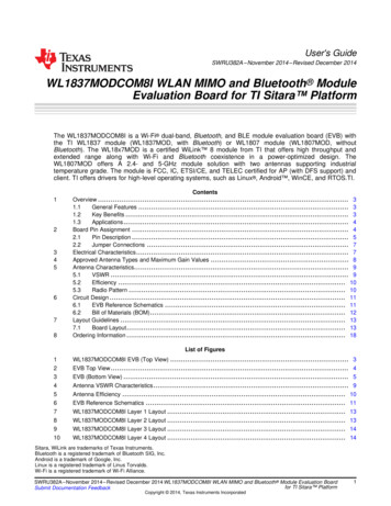
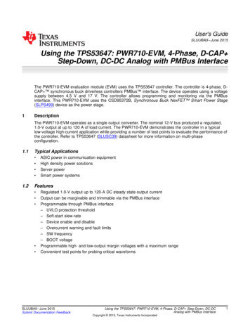
Test Setup4.3www.ti.comRecommended Test SetupFigure 11 shows the recommended test setup.Input Power Supply8 V to 14 V, 20 AInput Power Supply5 V, 1 AConnector forUSB-to-GPIO AdapterOutput Load1.0 V, 120 AFigure 11. PWR710-EVM Recommended Test Setup8Using the TPS53647: PWR710-EVM, 4-Phase, D-CAP Step-Down, DC-DCAnalog with PMBus InterfaceCopyright 2015, Texas Instruments IncorporatedSLUUBA9 – June 2015Submit Documentation Feedback
Test Setupwww.ti.com4.4USB Interface Adapter and CableFigure 12 shows the USB interface adapter and cable.Figure 12. Texas Instruments USB-to-GPIO Adapter and ConnectionsSLUUBA9 – June 2015Submit Documentation FeedbackUsing the TPS53647: PWR710-EVM, 4-Phase, D-CAP Step-Down, DC-DCAnalog with PMBus InterfaceCopyright 2015, Texas Instruments Incorporated9
Test Setup4.5www.ti.comList of Test Points and ConnectorsTable 3 lists the test point functions.Table 3. Test Point Functions10TEST POINTNAMEDESCRIPTIONTP1VINVIN measurement pointTP2GNDVIN– measurement pointTP295VIN5VIN measurement pointTP30GND5VIN– measurement pointTP311 8V LDO1.8-V external LDO output measurement pointTP323 3V LDO3.3-V external LDO output measurement pointTP18PWM1PWM signal of Phase 1TP19PWM2PWM signal of Phase 2TP20PWM3PWM signal of Phase 3TP21PWM4PWM signal of Phase 4TP22CSP1Current sense signal of Phase 1TP23CSP2Current sense signal of Phase 2TP24CSP3Current sense signal of Phase 3TP25CSP4Current sense signal of Phase 4TP3IMONIMON signalTP4TSENTSEN signalTP12P CLKPMBus clock signalTP13P ALERTPMBus alert signalTP14P DIOPMBus digital I/O signalTP16VR FAULTVR FAULT signalTP28ENABLEENABLE signalTP7VREFInternal reference voltage measurement pointTP6V3R3Internal 3.3-V LDO output measurement pointTP85V CON5-V power input measurement pointTP10RESETRESET signalTP11COMPCOMP signalTP9ISUMISUM signalTP15VR RDYVR RDY signalTP17VR HOTVR HOT signalTP5AGNDAnalog GroundUsing the TPS53647: PWR710-EVM, 4-Phase, D-CAP Step-Down, DC-DCAnalog with PMBus InterfaceCopyright 2015, Texas Instruments IncorporatedSLUUBA9 – June 2015Submit Documentation Feedback
EVM Configuration Using the Fusion GUIwww.ti.com5EVM Configuration Using the Fusion GUIThe controller on this EVM leaves the factory pre-configured. Table 4 lists some key factory configurationparameters from the configuration file.Table 4. Key Factory Configuration ParametersCMD 0x017.25 VTurn ON voltageIOUT OC FAULT LIMIT0x460x0096150.0 AOC fault levelIOUT OC WARN LIMIT0x4A0x0078120.0 AOC warning levelON OFF CONFIG0x020x17Control Pin onlyPower is converted when the controlpin is activeOT FAULT LIMIT0x4F0x007D125 COT fault levelOT WARN LIMIT0x510x005F95 COT warn levelMax Num Phases0xE40x034 Phase4 phase operationSWITCHING FREQUENCY0xDC0x20500kHz500kHz switching frequencyVBOOT0xDB0x971.00V1.0V VBOOT voltageTo configure the EVM with other than the factory settings shown in Table 4, use the TI Fusion DigitalPower Designer software for reconfiguration. Be sure to apply the input voltage to the EVM prior tolaunching the software. This sequence ensures that the controller and GUI recognize each other.5.1Configuration Procedure1.2.3.4.Adjust the input supply to provide 5 VDC, current limited to 1 A.Apply this input voltage to the EVM. Refer to Figure 11 and Figure 12 for connections and test setup.Launch the Fusion GUI software. Refer to the screenshots in Section 10 for more information.Configure the EVM operating parameters as desired.6Test Procedure6.1Line/Load Regulation and Efficiency Measurement Procedure1. Set up EVM as described in Figure 11.2. Ensure the electronic load is set to draw 0 Adc.3. Increase 5VIN from 0 V to 5 V.4. Increase VIN from 0 V to 12 V.5. Put switch S1 to ON position.6. Vary the load from 0 Adc to 120 Adc. Ensure VOUT remains in regulation as defined in Table 1.7. Vary VIN from 8 V to 14 V. Ensure VOUT remains in regulation as defined in Table 1.8. Decrease the load to 0 A.9. Put switch S1 to OFF position.10. Decrease VIN to 0 V.11. Decrease 5VIN to 0 V.6.2Control Loop Gain and Phase Measurement ProcedureThe PWR710 EVM includes a 0-Ω series resistor R64 in the feedback loop. This resistor value can bechanged to 10 Ω and then be used for loop response analysis, which is accessible at the connector J7and J8. These two connectors should be used during loop response measurements as the injection pointsfor the loop perturbation. See short description below in Table 5.SLUUBA9 – June 2015Submit Documentation FeedbackUsing the TPS53647: PWR710-EVM, 4-Phase, D-CAP Step-Down, DC-DCAnalog with PMBus InterfaceCopyright 2015, Texas Instruments Incorporated11
Test Procedurewww.ti.comTable 5. Test Points for Loop Response Measurements6.2.11.2.3.4.5.6.7.6.3TEST POINT NODENAMEDESCRIPTIONCOMMENTJ8 INPUTInput to feedback of VOUTThe amplitude of the perturbation at thisnode should be limited to less than 100 mV.J7 OUTPUTResulting output of VOUTBode can be measured by a networkanalyzer as J7 or J8 .ProcedureSet up EVM as described in Figure 11.Connect the network analyzer isolation transformer from J8 to J7 .Connect the input signal measurement probe to J8 .Connect output signal measurement probe to J7 .Connect the ground leads of both probe channels to J7– or J8–.On the network analyzer, measure the Bode as J7 or J8 (Out or In).Disconnect the isolation transformer from the bode plot test points and change the resistor R64 back to0 Ω before making other measurements, because the signal injection into the feedback loop mayinterfere with the accuracy of other measurements.EfficiencyIn order to measure the efficiency of the power train on the EVM, it is important to measure the voltages atthe correct location. This is necessary because otherwise the measurements will include losses that arenot related to the power train itself. Losses incurred by the voltage drop in the copper traces and in theinput and output connectors are not related to the efficiency of the power train, and they should not beincluded in efficiency measurements.Input current can be measured at any point in the input wires, and output current can be measuredanywhere in the output wires of the output being measured.Figure 13 shows the measurement points for input voltage and output voltage. Using these measurementpoints results in efficiency measurements that do not include losses due to the connectors and PWBtraces.12Using the TPS53647: PWR710-EVM, 4-Phase, D-CAP Step-Down, DC-DCAnalog with PMBus InterfaceCopyright 2015, Texas Instruments IncorporatedSLUUBA9 – June 2015Submit Documentation Feedback
Test Procedurewww.ti.comVINVOUTFigure 13. Test Setup for Efficiency Measurement6.4Equipment Turn-on and Shutdown6.4.11.2.3.4.Turn-on SequenceTurn on input power supply 5VIN.Turn on input power supply VIN and increase VIN above 8 V.Switch S1 to ‘ON’ position.Adjust load current as desired.1.2.3.4.5.Shutdown SequenceReduce the load current to 0 A.Switch S1 to ‘OFF’ position.Reduce input voltage VIN to 0 V.Shut down 5VIN.Shut down the external FAN if in use.6.4.2SLUUBA9 – June 2015Submit Documentation FeedbackUsing the TPS53647: PWR710-EVM, 4-Phase, D-CAP Step-Down, DC-DCAnalog with PMBus InterfaceCopyright 2015, Texas Instruments Incorporated13
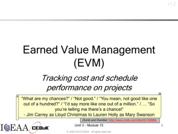
Performance Data and Typical Characteristic Curves7www.ti.comPerformance Data and Typical Characteristic CurvesFigure 14 through Figure 16 shows the typical performance curves for the PWR710-EVM.1001VIN 8 VVIN 12 VVIN 14 V950.9997590Output Voltage (V)8075706560VIN 8 VVIN 12 VVIN 14 V550.99950.999250.9990.99875500.9985010203040 50 60 70 80Output Current (A)90 100 110 12001020D001Figure 14. Efficiency of vs Line and Load (VOUT 1.0 V)40 50 60 70 80Output Current (A)80200GainPhase 0090 100 110 120D001Figure 15. . Load Regulation (VOUT 1.0 V)100Gain (dB)3010000100000Frequency (Hz)Phase ( )Efficiency (%)85-2001000000D002D008D001Figure 16. Bode Plot (VIN 12 V, VOUT 1.0 V, 120A)14Using the TPS53647: PWR710-EVM, 4-Phase, D-CAP Step-Down, DC-DCAnalog with PMBus InterfaceCopyright 2015, Texas Instruments IncorporatedSLUUBA9 – June 2015Submit Documentation Feedback
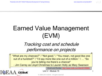
Performance Data and Typical Characteristic Curveswww.ti.comFigure 17 through Figure 22 show the waveforms for the PWR710-EVM.VIN 12 V, VOUT 1 V, Div 5 A/µsVIN 12 V, VOUT 1 V, Div 5 A/µsFigure 17. Transient Response Load Step 0 A to 40 AVIN 12 V, VOUT 1 V, Div 5 A/µsIOUT 120 A, VIN 12 V, VOUT 1 V, Div 5 A/µsFigure 19. Transient Response(Load Step 0 A to 40 A to 0A)SLUUBA9 – June 2015Submit Documentation FeedbackFigure 18. Transient Response (Load Step 40 A to 0 A)Figure 20. Output RippleUsing the TPS53647: PWR710-EVM, 4-Phase, D-CAP Step-Down, DC-DCAnalog with PMBus InterfaceCopyright 2015, Texas Instruments Incorporated15
Performance Data and Typical Characteristic CurvesIOUT 0 A, VIN 12 V, VOUT 1 V, Div 5 A/µswww.ti.comIOUT 6 A, VIN 12 V, VOUT 1 V, Div 5 A/µsFigure 21. Enable Startup16Figure 22. Enable ShutdownUsing the TPS53647: PWR710-EVM, 4-Phase, D-CAP Step-Down, DC-DCAnalog with PMBus InterfaceCopyright 2015, Texas Instruments IncorporatedSLUUBA9 – June 2015Submit Documentation Feedback
EVM Assembly Drawing and PCB Layoutwww.ti.com8EVM Assembly Drawing and PCB LayoutFigure 17 through Figure 26 show the design of the PWR710 EVM printed circuit board.Figure 23. Top Layer Assembly Drawing (Top View)Figure 24. Bottom Assembly Drawing (Bottom view)Figure 25. Top Copper (Top View)Figure 26. Internal Layer 1 (Top View)SLUUBA9 – June 2015Submit Documentation FeedbackUsing the TPS53647: PWR710-EVM, 4-Phase, D-CAP Step-Down, DC-DCAnalog with PMBus InterfaceCopyright 2015, Texas Instruments Incorporated17
EVM Assembly Drawing and PCB Layout18www.ti.comFigure 27. Internal Layer 2 (Top View)Figure 28. Internal Layer 3 (Top View)Figure 29. Internal Layer 4 (Top View)Figure 30. Internal Layer 5 (Top View)Using the TPS53647: PWR710-EVM, 4-Phase, D-CAP Step-Down, DC-DCAnalog with PMBus InterfaceCopyright 2015, Texas Instruments IncorporatedSLUUBA9 – June 2015Submit Documentation Feedback
EVM Assembly Drawing and PCB Layoutwww.ti.comFigure 31. Internal Layer 6 (Top View)SLUUBA9 – June 2015Submit Documentation FeedbackFigure 32. Bottom Copper (Top View)Using the TPS53647: PWR710-EVM, 4-Phase, D-CAP Step-Down, DC-DCAnalog with PMBus InterfaceCopyright 2015, Texas Instruments Incorporated19
List of Materials9www.ti.comList of MaterialsTable 6. List of MaterialsQTY20REF DESDESCRIPTIONPART NUMBERMANUF1PCBPrinted Circuit BoardPWR710Any14C1, C2, C4, C5, C6,C7, C8, C9, C14,C15, C16, C17, C18,C19Capacitor, ceramic 22 µF, 25 V, 20%, X5R,1206 190C3216X5R1E226M160ABTDK1C3Capacitor, ceramic 2200 pF, 50 V, 10%,X7R, 0603C0603C222K5RACKemet4C10, C11, C21, C22Capacitor, ceramic 3300 pF, 50 V, 10%,X7R, 0402C1005X7R1H332KTDK2C12, C13CAP, AL, 270 µF, 16 V, 20%, 0.01 ohm, TH16SEPC270MXPanasonic1C20Capacitor, ceramic 1000 pF, 16 V, 10%,X7R, 0603GRM188R71C102KA01DMuRata2C23, C29Capacitor, ceramic 1 µF, 10 V, 10%, X7R,0603GRM188R71A105KA61DMuRata1C24Capacitor, ceramic 0.33 µF, 10 V, 10%, X7R, GRM188R71A334KA060361DMuRata1C25Capacitor, ceramic 4.7 µF, 16 V, 10%, X5R,0603GRM188R61C475KAAJMuRata1C26Capacitor, ceramic 1 µF, 25 V, 10%, X7R,0603GRM188R71E105KA12DMuRata1C27Capacitor, ceramic 1000 pF, 25 V, 5%,C0G/NP0, 0603GRM1885C1E102JA0 MuRata1D1C28Capacitor, ceramic 12 pF, 50 V, 5%,C0G/NP0, 0603GRM1885C1H120JA0 MuRata1D10C30, C31, C32, C47,C48, C49, C50, C63,C64, C97Capacitor, ceramic 0.1 µF, 25 V, 10%, X7R,0603GRM188R71E104KA01DMuRata4C33, C34, C51, C52Capacitor, ceramic 2.2 µF, 10 V, 10%, X7R,0603GRM188R71A225KE15DMuRata8C35, C36, C37, C38,C53, C54, C55, C56Capacitor, ceramic 1000 pF, 25 V, 10%,X7R, 0603GRM188R71E102KA01DMuRata4C39, C40, C57, C58Capacitor, ceramic 1000 pF, 50 V, 10%,X7R, 0402GRM155R71H102KA01DMuRata4C41, C42, C59, C60Capacitor, ceramic 1000 pF, 50 V, 5%,C0G/NP0, 0603GRM1885C1H102JA0 MuRata1D6C43, C44, C45, C46,C61, C62CAP, Aluminum Polymer, 470 µF, 2.5 V,EEF-GX0E471R 20%, 0.003 ohm, SMD 7.3x1.9x4.3mm SMD30C65,C69,C73,C77,C81,C85,C89,C93,Capacitor, ceramic 100 µF, 4 V, 20%, X5R,12061C95Capacitor, ceramic 0.01 µF, 25 V, 10%, X7R, GRM188R71E103KA060301DMuRata3C96, C98, C99Capacitor, ceramic 10 µF, 10 V, 20%, X5R,0805GRM219R61A106ME47MuRata6FID1, FID2, FID3,FID4, FID5, FID6Fiducial mark. There is nothing to buy ormount.N/AN/A6J1, J2, J10, J11, J12,J13Terminal 50A LugCB35-36-CYPanduit1J3Header, 100mil, 2x2, Gold, THTSW-102-07-G-DSamtec1J4Header, 100mil, 5x2, Gold, ,C88,C92,Using the TPS53647: PWR710-EVM, 4-Phase, D-CAP Step-Down, DC-DCAnalog with PMBus InterfaceCopyright 2015, Texas Instruments IncorporatedPanasonicGRM31CR60G107ME MuRata39LSLUUBA9 – June 2015Submit Documentation Feedback
List of Materialswww.ti.comTable 6. List of Materials (continued)QTYREF DESDESCRIPTIONPART NUMBERMANUF4J5, J7, J8, J9Header, 100mil, 2x1, Gold, THTSW-102-07-G-SSamtec1J6Header, 100mil, 3x1, Gold, THTSW-103-07-G-SSamtec1J14Terminal Block, 6A, 3.5mm Pitch, 2-Pos, THED555/2DSOn-Shore Technology1L1Inductor, ?, 65 nH, 24 A, 0.00032 ohm, SMD59PR65-650Vitec Corporation4L2, L3, L4, L5Inductor, ?, Ferrite, 150 nH, 41 A, 0.00029ohm, SMDPA2607.151NLTPulse Engineering1R1RES, 49.9 k, 1%, 0.1 W, 0603CRCW060349K9FKEAVishay-Dale2R2, R25RES, 150 k, 1%, 0.1 W, 0603CRCW0603150KFKEAVishay-Dale2R3, R20RES, 20.0 k, 1%, 0.1 W, 0603CRCW060320K0FKEAVishay-Dale23R4, R28, R33, R34,R35, R36, R39, R40,R41, R49, R50, R51,R52, R55, R56, R61,R62, R63, R64, R65,R66, R69, R70Resistor, 0, 5%, 0.1 W, 0603MCR03EZPJ000Rohm1R5Resistor, 121 kΩ, 1%, 0.1 W, 0603CRCW0603121KFKEAVishay-Dale9R6, R29, R30, R43,R44, R45, R46, R59,R60Resistor, 1.00, 1%, 0.1 W, 0603CRCW06031R00FKEAVishay-Dale1R7Resistor, 2.55 kΩ, 1%, 0.1 W, 0603CRCW06032K55FKEAVishay-Dale2R8, R76Resistor, 2.00 kΩ, 1%, 0.1 W, 0603CRCW06032K00FKEAVishay-Dale1R9Resistor, 8.06 kΩ, 1%, 0.1 W, 0603CRCW06038K06FKEAVishay-Dale1R10Resistor, 26.7 kΩ, 1%, 0.1 W, 0603CRCW060326K7FKEAVishay-Dale1R11Resistor, 9.31 kΩ, 1%, 0.1 W, 0603CRCW06039K31FKEAVishay-Dale2R12, R13Resistor, 16.5 kΩ, 1%, 0.1 W, 0603CRCW060316K5FKEAVishay-Dale1R14Resistor, 4.32 kΩ, 1%, 0.1 W, 0603CRCW06034K32FKEAVishay-Dale1R15Resistor, 33.2 kΩ, 1%, 0.1 W, esistor, 10.0 kΩ, 1%, 0.1 W, 0603CRCW060310K0FKEAVishay-Dale2R19, R21Resistor, 24.3 kΩ, 1%, 0.1 W, 0603CRCW060324K3FKEAVishay-Dale1R24Resistor, 39.2 kΩ, 1%, 0.1 W, 0603CRCW060339K2FKEAVishay-Dale3R27, R42, R57Resistor, 30.1 kΩ, 1%, 0.1 W, 0603CRCW060330K1FKEAVishay-Dale1R58Resistor, 51.1 kΩ, 1%, 0.1 W, 0603CRCW060351K1FKEAVishay-Dale1R71Resistor, 1.00 kΩ, 1%, 0.1 W, 0603CRCW06031K00FKEAVishay-Dale2R72, R73Resistor, 1.0, 5%, 0.125 W, 0805CRCW08051R00JNEAVishay-Dale1R74Resistor, 100 kΩ, 1%, 0.1 W, ,R31,R47,R67,SLUUBA9 – June 2015Submit Documentation FeedbackR22,R32,R48,R68Using the TPS53647: PWR710-EVM, 4-Phase, D-CAP Step-Down, DC-DCAnalog with PMBus InterfaceCopyright 2015, Texas Instruments Incorporated21
Fusion GUIwww.ti.comTable 6. List of Materials (continued)QTY10REF DESDESCRIPTIONPART NUMBERMANUF1R75Resistor, 15.0 kΩ, 1%, 0.1 W, 0603CRCW060315K0FKEAVishay-Dale1S1Switch, SPDT, Slide, On-On, 2 Pos, THEG1218E-Switch5TP1, TP26, TP29,TP31, TP32Test Point, Miniature, Red, TH5000Keystone4TP2, TP5, TP27,TP30Test Point, Miniature, Black, TH5001Keystone23TP3, TP4, TP6, TP7,TP8, TP9, TP10,TP11, TP12, TP13,TP14, TP15, TP16,TP17, TP18, TP19,TP20, TP21, TP22,TP23, TP24, TP25,TP28Test Point, Miniature, White, TH5002Keystone1U14-Phase, D-CAP TM Step-Down BuckController with NVM and PMBus Interface,RHA0040BTPS53647RHATI4U2, U3, U4, U5Synchronous Buck NexFET Power Stage,DQP0012ACSD95372BQ5MTI1U6Dual Output LDO, 500 mA, 2.7 to 6 V Input,20-pin HTSSOP (PWP)TPS70102PWPTIFusion GUIWhen the Fusion GUI launches, it restored user preferences and data.Figure 33. Launch Fusion GUIUse the General Configure screen as shown in Figure 34 to configure these specifications: VBOOT VOUT Command VIN UVLO IIN OC Fault and OC Warn IOUT OC Fault and OC Warn OT Fault OT Warn IMAX On/Off Config Margin voltage Phase number22Using the TPS53647: PWR710-EVM, 4-Phase, D-CAP Step-Down, DC-DCAnalog with PMBus InterfaceCopyright 2015, Texas Instruments IncorporatedSLUUBA9 – June 2015Submit Documentation Feedback
Fusion GUIwww.ti.comFigure 34. General ConfigureSLUUBA9 – June 2015Submit Documentation FeedbackUsing the TPS53647: PWR710-EVM, 4-Phase, D-CAP Step-Down, DC-DCAnalog with PMBus InterfaceCopyright 2015, Texas Instruments Incorporated23
Fusion GUIwww.ti.comUse the Advanced Configure screen as shown in Figure 35 to configure these specifications: USR and OSR Load-line RAMP Switching Frequency Phase Interleaving Dynamic Phase Shedding Slew RateFigure 35. Advanced Configure24Using the TPS53647: PWR710-EVM, 4-Phase, D-CAP Step-Down, DC-DCAnalog with PMBus InterfaceCopyright 2015, Texas Instruments IncorporatedSLUUBA9 – June 2015Submit Documentation Feedback
Fusion GUIwww.ti.comUse the [Configure All] screen as shown in Figure 36 to configure all of the configurable parameters. Thisscreen shows other details such as Hexadecimal encoding.Figure 36. Configure AllSLUUBA9 – June 2015Submit Documentation FeedbackUsing the TPS53647: PWR710-EVM, 4-Phase, D-CAP Step-Down, DC-DCAnalog with PMBus InterfaceCopyright 2015, Texas Instruments Incorporated25
Fusion GUIwww.ti.comAfter the user selects a change, the GUI displays an orange “U” icon, offering an [Undo Change] option.The software does not retain a change until the use selects either [Write to Hardware] or [Store UserDefaults].When [Write to Hardware] is selected, the change is committed to volatile memory and defaults back toprevious setting upon input power cycle. When a user selects [Store User Defaults], the software commitsthe change to non-volatile memory and it becomes the new default Figure 37.Figure 37. General Configure Pop-Up26Using the TPS53647: PWR710-EVM, 4-Phase, D-CAP Step-Down, DC-DCAnalog with PMBus InterfaceCopyright 2015, Texas Instruments IncorporatedSLUUBA9 – June 2015Submit Documentation Feedback
Fusion GUIwww.ti.comWhen user selects the [Monitor] screen (shown in Figure 38) the screen changes to display real-time dataof the parameters that are measured by the controller. This screen provides access to the folowingparameters: Graphs of– VOUT– IOUT– Temperature– POUT (as shown in Figure 38, the POUT display is turned OFF Start/Stop Polling controls ON or OFF the real-time display of data Quick access to ON or OFF configuration Control pin activation, and OPERATION command Margin control Clear Fault clears any prior fault flagsFigure 38. Monitor ScreenSLUUBA9 – June 2015Submit Documentation FeedbackUsing the TPS53647: PWR710-EVM, 4-Phase, D-CAP Step-Down, DC-DCAnalog with PMBus InterfaceCopyright 2015, Texas Instruments Incorporated27
Fusion GUIwww.ti.comSelecting [System Dashboard] from mid-left screen adds a new window which displays system levelinformation Figure 39.Figure 39. System Dashboard28Using the TPS53647: PWR710-EVM, 4-Phase, D-CAP Step-Down, DC-DCAnalog with PMBus InterfaceCopyright 2015, Texas Instruments IncorporatedSLUUBA9 – June 2015Submit Documentation Feedback
Fusion GUIwww.ti.comSelecting [Status] from lower left corner shows the status of the controller Figure 40.Figure 40. Status ScreenSLUUBA9 – June 2015Submit Documentation FeedbackUsing the TPS53647: PWR710-EVM, 4-Phase, D-CAP Step-Down, DC-DCAnalog with PMBus InterfaceCopyright 2015, Texas Instruments Incorporated29
Fusion GUIwww.ti.comSelecting the pull down menu [File] [Import Project] from the upper left menu bar can be used toconfigure all parameters in the device at once with a desired configuration, or even revert back to a“known-good” configuration (as shown in Figure 41) . This action results in a browse-type sequence toallow the user to locate and lock the desired configure file.Figure 41. Import Configuration File30Using the TPS53647: PWR710-EVM, 4-Phase, D-CAP Step-Down, DC-DCAnalog with PMBus InterfaceCopyright 2015, Texas Instruments IncorporatedSLUUBA9 – June 2015Submit Documentation Feedback
STANDARD TERMS AND CONDITIONS FOR EVALUATION MODULES1.Delivery: TI delivers TI evaluation boards, kits, or modules, including any accompanying demonstration software, components, ordocumentation (collectively, an “EVM” or “EVMs”) to the User (“User”) in accordance with the terms and conditions set forth herein.Acceptance of the EVM is expressly subject to the following terms and conditions.1.1 EVMs are intended solely for product or software developers for use in a research and development setting to facilitate feasibilityevaluation, experimentation, or scientific analysis of TI semiconductors products. EVMs have no direct function and ar
VSN PWRGND CSP2 CSP3 ADDR_TRISE VR_HOT# ENABLE VR_RDY VR_FAULT# PMB_DIO PMB_ALERT# PMB_CLK TSEN SLEW-MODE AGND PWRGND OCP-R VSP VSN CSP3 CSP2 CSP4 CSP1 V3R3 VIN_C SKIP#_NVM PWM2 ENABLE . EVM was designed to use the Texas Instruments USB-to-GPIO adapter, see Figure 12. To purchased this adapter visit the TI usb-to-gpio tool page. 6 Using the .