Transcription
POWER SYSTEMS TOPICS 111Paralleling Switchgear:DOCUMENTING THE SEQUENCE OFOPERATION WITH CHARTS LOADSINTRODUCTIONThe sequence of operation for a paralleling switchgear project can be complex.Because no two power systems are exactly the same, each should be customdesigned to meet the requirements and challenges associated with theproject application. To reduce guesswork and ambiguity during system designand operation, Kohler Power Systems has developed sequence charts thatdocument how a system will respond to both normal operations and systemfailures. This intuitive approach helps ensure that the system will operate asdesigned with no surprises.A concise, detailed sequence of operation is perhaps the single most importantstep when designing paralleling switchgear (or any system capable of automaticoperation). A traditional narrative-based sequence of operation may not clearlyillustrate the timing of events or combine normal operation with how the systemresponds to failure. Kohler’s unique chart-based sequence of operation offers anumber of benefits including step-by-step explanation of sequence, timing andresponse to failure. These multipurpose charts can also be used for submittalreviews, test procedures, and operation and maintenance manuals. Theyprovide a single point of reference when seeking to understand the operation ofthe paralleling switchgear.This article describes the sequence chart approach, how a chart is customcreated for an individual system and its benefits in the design, testing andtraining processes.
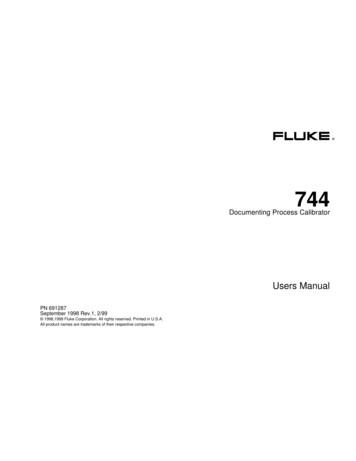
DESIGNING A PARALLELINGSWITCHGEAR PROJECTThere are four distinct stages of designing aparalleling switchgear system.I. CREATING THE SINGLE-LINE DRAWINGIII. SELECTING CONTROLSThe single-line drawing illustrates howcomponents of the electrical system areconnected and the available routes throughwhich power may travel in the system.Controls enable a system to perform thespecified sequences, allow for operatorinteraction and provide all required meteringand protection. During the control selectionphase, consideration should be given to boththe level and redundancy of the automaticcontrols, as well as to any manual controlsrequired for operator intervention in the eventof an automatic control failure.II. ESTABLISHING THE SEQUENCEOF OPERATIONThe sequence of operation describes the stepsthe system will take to change from one state toanother, such as moving from “on utility power”to “on generator power.”A well-written sequence will describe bothnormal operation and any alternate sequencesthe system takes if there is a failure duringnormal operation.IV. DETERMINING THE SWITCHGEARSTRUCTUREThe structure of the paralleling switchgearlineup is the physical representation of thesingle line. It contains the circuit breakers,controls and meters.SEQUENCE CHART (EXAMPLE)INITIALSTATESection 1 Modes of Operation1.1Emergency Mode1.1.1Loss of utilitySTEP1.1.2The return to utility is controlled by the return toutility control switch1. The closed utility breaker opens.Return to utility control switch2. The generators start.4. The other generator synchronizes to thebus. When synchronized, its circuit breakercloses.6. If the generator management control is inAUTO, the system will monitor the powerdemand of the load, if the load demand isbelow the setpoints set by the operator, thesystem will automatically take a generatoroff-line. If the load should increase, thesystem will automatically place thegenerator back on-line. See section 5.7 for adescription of the generator managementlogic.7. If the system becomes overloaded or if agenerator fails, the system will close a set ofnormally open dry contacts signalingdownstream load to shed.GMAGen BusGMBBus BXEODOEEVENTRESPONSE1Utility A and utility B out of tolerance.Utility A Failure timer starts.2Both utility failure timers expire orone timer expired while the otheris still timing.UBXIF FAILAUtility B Failure timer starts.BUtility breaker UA opens.CUtility breaker UB opens.DAll available generators start.Required GOL Bypass timer starts.ManualAuto5. With both generators on-line, the tie breakercloses.NOTE: Using the HMI, the operator canpreset the system to automatically signal aload shed and then close the tie breaker ifthe second generator fails to go on-line.Bus AReturn of utilityThe loss of starts engine start delay timer in thePLC. If this timer expires, than the followingsequence occurs:3. The first generator to reach 90% of ratedvoltage and frequency closes onto the bus.First-on logic prevents both generators fromclosing onto the bus simultaneously.UAReturnThe system remains on generatorpower until the operator depresses theReturn or Auto pushbutton. The Utilitystable timer does not time.When utility returns, the utility stabletimer in the PLC starts. When the utilitystable timer expires the systemautomatically starts the return to utilitysequence.If the system is on generatorpower and utility power is available,depressing the Return pushbuttoninitiates the return to utility sequence.If open transfer mode is selected1. The tie breaker and the generator breakersopen.3Utility breaker UA is open.4Utility breaker UB is open.5The first generator reaches ratedvoltage and frequency.The first generator breaker closes.6The remaining generators independentlyreach rated voltage and frequency.The remaining generators independently synchronize tothe bus and close their respective circuit breakers.7Required generators are online and thebus A Open Transfer timer expired.Generator main breaker GMA closes.8Generator main breaker GMA is closed.Bus A is on generator power.9Generator Stabilization timer expires andbus B Open Transfer timer expired.Generator main breaker GMB closes.10Generator main breaker GMB is closed.Bus B is on generator power.11Bus A and B on generator power.Startup Shed Option:Based on the Load-Management settings,loads are added to the bus A and B.Bus A Open Transfer timer starts.Startup Shed Option:Based on the Load-Management settings,loads on bus A are shed.Bus B Open Transfer timer starts.Startup Shed Option:Based on the Load-Management settings,loads on bus B are shed.2. After the open transfer delay timer expires,the utility breaker closes.3. The generators shut down after completinga cool down cycle.4.E, FGRequired GOL Bypass timer stops.Generator Stabilization timer starts.HIf closed transfer mode is selected1. The generators synchronize to the utility.2. When synchronized, the utility breakercloses.3. The generators soft (ramp) unloads.4. When the power flow across the tie breakerreaches its unloaded trip point, the tiebreaker and the generator breakers open.5. The generators shut down after completinga cool down cycle.Traditional Narrative-Based Chart2 / Paralleling SwitchgearIGenerator Management Option:Becomes active if in Auto and all loads have been added.FINALSTATEUABus AGMAGen BusGMBBus BUBOEXEXEOKohler Chart-Based Sequence of Operation
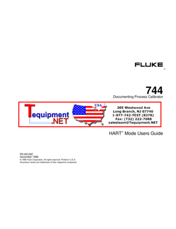
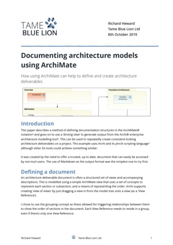
POWER SYSTEMS TOPICS 111Single-Line DiagramM2GM2M1GM1F1F2G1F5F4F6G2F3Each stage builds on the previous one; followingthem in order is key to a successful project.While progressing through each design stage, itis important to review decisions made in theprior stages to be sure they remain valid andmake any necessary adjustments if changes aremade. For example, if the drawing is revised toadd a bus tie breaker to the single line, it isimportant that the sequence is updated toindicate the purpose of the tie breaker and itsrole in the sequence of operation.Each of the four stages used to designparalleling switchgear is vital to the creationof a cohesive system. However, the mostchallenging—and often the most important forproper operation—is establishing the sequenceof operation. This is especially important forcomplex projects with multiple utilities, where adetailed and precise sequence of operationprovides the foundation upon which the projectis built. Critical to the sequence of operation isan understanding of how the system worksnormally and how it responds if there is a failurein the normal sequence, such as a breakerfailing to open or close.NEW APPROACH-SEQUENCE CHARTSThe unique charts developed by KOHLERPower Systems are a distinctive approachto documenting the sequence of operation.These intuitive charts offer benefits for everyoneinvolved in the design and operation ofthe project. They eliminate the ambiguity of knowing how thesystem responds to both normal operations andsystem failure. They are easier to read than a typical flowchart. They clearly show system response, timingof response, and what the system and operator cando if the system fails to respond properly. They provide a checklist for testing andcommissioning the paralleling switchgear.Each sequence has two charts—the sequence itselfand the response to abnormal conditions. The sequence lists the steps the systemwill take from the initial state to the final state aswell as the expected system response to each step. The response to abnormal conditionsdescribes the system response and theaction an operator can take if the systemdoes not respond as expected to an event.The chart-based method describes the operationthat a typical paralleling switchgear sequencetakes in a series of steps that transition from aninitial state, such as “on utility power,” to a finalstate, such as “on generator power.” The numberof charts for an individual project will varydepending on the number of normal states andthe different types of transitions, such as open orclosed, between the states.Paralleling Switchgear / 3
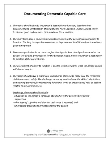
THE FIVE STEPS IN CREATING A SEQUENCE CHARTLet’s look at the five steps we take in creating the chart, and how they illustrate–in sequence—thesystem’s loss of both utilities. The sequence to transfer from utility power is described in a series ofsteps. Within each step are an event and a corresponding system response to the event.Simultaneous responses to the same event are shown as separate response lines.THE FIVE STEPS IN CREATING ASEQUENCE CHARTDETERMINE THE INITIAL STATEThe initial state shows the status of each breakerin the power transfer sequence and the powerstatus of each bus in the system.In the initial state, the system is on utility power, UtilityBreaker A (UA) and Utility Breaker B (UB) are closed, andmain breakers Generator Main A (GMA) and GeneratorMain B (GMB) are open. The chart shows the status of eachbreaker that is part of the power transfer sequence and thepower status of each of the three buses in the system.DEFINE THE TRIGGERING EVENTThe triggering event starts the sequence.Examples might be the receipt of a remote startsignal, the utility being out of tolerance or anoperator pushing a button. For example, in Step1, when UA and UB are out of tolerance, both theUA Failure timer and the UB Failure timer start.The “if fail” column directs the operator to the corresponding letter on the “response to abnormal conditions” chart,explaining how the system reacts if it does not respond asexpected. In this example, the “if fail” describes theresponse that occurs if utility power returns before thefailure timers expire.LIST EACH EVENT (STEP) ANDCORRESPONDING RESPONSEEach step required to transition from initial stateto desired final state is described. Each row inthe sequence lists the required change in systemstate and the corresponding system response.For example, if a system is performing an opentransfer back to the utility after a power outage,one of the events might be the opening of thegenerator main breaker and the startup of theopen transfer timer (event/corresponding systemresponse). See chart on Page 5.4 / Paralleling SwitchgearThe power of the chart becomes evident in the next step ofthe sequence. When both utility failure timers expire or onetimer expires while the other is still timing, the followingthings happen simultaneously: Utility breaker UA opens Utility breaker UB opens All available generators start Required GOL (Generator Online) Bypass timer startsThe chart not only shows how a systemresponds to an event but also when eachresponse occurs. By showing each responseon a separate line, the operator can refer to thecorresponding step on the “response toabnormal conditions” chart to determine howto correct an “if fail” scenario.LIST THE FINAL STATE OF THE SYSTEMThe final state of the system is described foreach breaker within the power transfer sequenceand the power status of each bus in the system.DETERMINE “IF FAIL” SCENARIOSEach system response is reviewed to determineif an “if fail” scenario is needed. In general, an“if fail” scenario is required for any response thatinvolves a breaker opening or closing or a timerstarting. This step preplans how the systemshould respond if a breaker fails to open or closeor if something happens and a fail-safe timerexpires. Responses that require an “if fail”scenario include a generator failing to start, agenerator failing while running or generatorsbecoming overloaded. In an “if fail” scenario, the“if fail” column in the sequence chart referencesthe corresponding step in the “response toabnormal conditions” chart, describing thesystem’s automatic response to that failure andthe actions an operator should take to correctthe system.
POWER SYSTEMS TOPICS 111SEQUENCE CHART (EXAMPLE)INITIALSTATE12STEPBus AGMAGen BusGMBBus BUBXEODOEXEVENT13UARESPONSEUtility A Failure timer starts.AUtility B Failure timer starts.BUtility breaker UA opens.CUtility breaker UB opens.DUtility A and utility B out of tolerance.52IF FAILBoth utility failure timers expire or onetimer expired while the other is still timing.All available generators start.Required GOL Bypass timer starts.Bus A Open Transfer timer starts.3Utility breaker UA is open.Startup Shed Option:Based on the Load-Management settings,loads on bus A are shed.Bus B Open Transfer timer starts.4Utility breaker UB is open.5The first generator reaches ratedvoltage and frequency.The first generator breaker closes.6The remaining generators independentlyreach rated voltage and frequency.The remaining generators independently synchronize tothe bus and close their respective circuit breakers.7Required generators are online and thebus A Open Transfer timer expired.Generator main breaker GMA closes.8Generator main breaker GMA is closed.Startup Shed Option:Based on the Load-Management settings,loads on bus B are shed.E, FGBus A is on generator power.Required GOL Bypass timer stops.Generator Stabilization timer starts.9Generator Stabilization timer expires andbus B Open Transfer timer expired.Generator main breaker GMB closes.10Generator main breaker GMB is closed.Bus B is on generator power.Bus A and B on generator power.Startup Shed Option:Based on the Load-Management settings,loads are added to the bus A and B.11HIGenerator Management Option:Becomes active if in Auto and all loads have been added.4FINALSTATEUABus AGMAGen BusGMBBus BUBOEXEXEOParalleling Switchgear / 5
Response to Abnormal Conditions ChartRESPONSE TO ABNORMAL CONDITIONS CHART (EXAMPLE)STEP FAILAEVENTUtility A power returnsbefore Utility A FailureSYSTEM RESPONSEOPERATOR ACTIONBus A remains on utility A.No operator action required.Bus B remains on utility B.No operator action required.Utility breakerUtility A remains failed,Option #1:UA fails to open.Utility B remains failed:Reset the Fail to Open alarm. System attempts to open utility breakerBus A is without power. Generatormain breakerUA. When breaker opens, transfer automatically continues.GMA does not close. AfterOption #2:Manually open utility breaker UA. Transfer automatically continues iftimer expires.BUtility B power returnsbefore Utility B Failuretimer expires.Cthe required generatorsare online, generator main breakersystem is in Auto.GMB closes.Option #3:Utility A remains failed,Utility B returns: Bus A is without1. Place system in Manual.3. If required, shed load.2. Manually open utility4. Manually close generatorbreaker UA.main breaker GMA.No operator action required.power. The system transfers busB from generator power to utility Bpower following the expiration ofthe Utility B Stable timer.Utility A returns, Utility B remainsOperator may manually transfer bus B from generator power to utility Afailed: Bus A remains on utility A.power.Bus B remains on generator power.Utility A and Utility B return:Bus A remains on utility A.No operator action required.The system transfers bus B fromgenerator power to utility B powerfollowing the expiration of theUtility B Stable timer.DUtility breaker UBfails to open.Utility B remains failed, Utility Aremains failed: Bus B is withoutOption #1:Reset the Fail to Open alarm. System attempts to open utility breakerpower. Generator main breakerUB. When breaker opens, transfer automatically continues.GMB does not close.6 / Paralleling Switchgear
POWER SYSTEMS TOPICS 111THE PAYOFF OF KOHLER’S CHART-BASED APPROACHImplementing a chart-based sequence ofoperation instead of a narrative-based sequenceprovides a way to comprehensively cover the“what ifs” while the project is still in the designstage. In addition, the sequence of operationschart serves as a checklist during testing toprovide better quality assurance. In many cases,by simulating the sequence of operation anddocumenting it, the equipment performs at ahigher level, onsite start-up time decreases andreliability increases.Kohler’s chart-based approach to the sequenceof operation provides a more effective way tolook at sequencing. It ensures the stage isdescribed without ambiguity, and each step isclearly explained. More important, if a systemfailure occurs, the system’s response is alreadyknown—often eliminating guesswork andminimizing system interruption. Making complexsystems simple—that’s the Kohler difference.Paralleling Switchgear / 7
POWER SYSTEMS TOPICS 111A global force in power solutions since 1920, Kohler is committed to reliable,intelligent products; purposeful engineering and responsive after-sale support.Kohler’s acquisition of SDMO in 2005 created one of the world’s largestmanufacturers of industrial generators. The companies have a combined 150 yearsexperience in industrial power and now benefit from global R&D, manufacturing,sales, service and distribution integration.KOHLERPOWER.COMPrinted in U.S.A.G26-22 KPS 111 1/18 2018 by Kohler Co.
2 / Paralleling Switchgear DESIGNING A PARALLELING SWITCHGEAR PROJECT There are four distinct stages of designing a paralleling switchgear system. I. CREATING THE SINGLE-LINE DRAWING The single-line drawing illustrates how components of the electrical system are connected and the available routes through which power may travel in the system. II.