Transcription
744Documenting Process Calibrator HART Mode Users GuidePN 691292December 1998 1998 Fluke Corporation, All rights reserved. Printed in U.S.A.All product names are trademarks of their respective companies.
Table of ContentsTitleIntroduction .How to Contact Fluke .Connecting to a HART Transmitter .Supported vs. Generic Transmitters .Communication Operations .Viewing Process Variables .Setup Operations .Basic .Sensor.Device Identification .HART Output .HART Information .Service Operations .Abort Softkey .Interaction between Analog Mode and HART Mode .Understanding HART Calibration .744 HART Mode Menus for Adjustment.iPage12368888101011111212121313
744HART Mode Users GuideCalibrating a Supported HART Transmitter .Loop Test.Output Trim.Sensor Trim .Cloning a Transmitter .Indexii1516171719
List of TablesTable1.TitlePageSupported vs. Non-Supported Instruments. 7iii
744HART Mode Users Guideiv
List of FiguresFigure1.2.3.TitlePageConnecting to a HART Transmitter. 5744 HART Mode Menu Tree. 9Block Diagram of a HART Transmitter . 14v
744HART Mode Users Guidevi
Documenting Process Calibrator HART ModeIntroductionw WarningTo avoid electric shock, read the SafetyInformation in the 744 Users Manual beforeyou use the Fluke 744 Documenting ProcessCalibrator.With analog transmitters, you must make a hardwareadjustment during calibration. With HART (HighwayAddressable Remote Transducer) transmitters,adjustments are by remote command. These adjustmentsrequire the use of a communication tool as well as acalibrator. The Fluke 744, hereafter called “calibrator,”provides communication and calibration functions in onetool.This manual describes how to use HART mode, which isactive when the calibrator is communicating over its serialHART interface to a HART transmitter. Refer to the744 Users Manual for safety, analog mode operatinginstructions, specifications, and other general information.All of the calibrator functions described in the 744 UsersManual are available and can be used with HARTtransmitters. The only transmitters addressed in thismanual are HART transmitters.1
744HART Mode Users GuideHow to Contact FlukeTo contact Fluke, call:USA and Canada:1-888-99-FLUKE (1-888-993-5853)Europe: 31 402-678-200Japan: 81-3-3434-0181Singapore: 65-*-276-6196Anywhere in the world: 1-425-356-5500Or visit us on the World Wide Web: www.fluke.com2
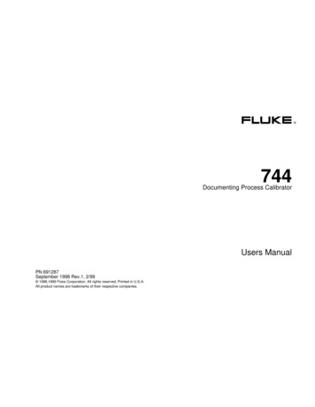
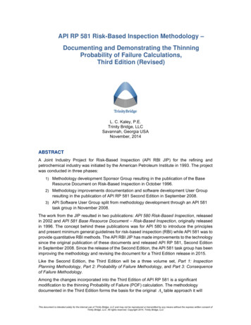
Documenting Process Calibrator HART ModeConnecting to a HART TransmitterConnecting to a HART Transmitter4.To connect to and begin to communicate with a HARTtransmitter, refer to Figure 1 and proceed as follows:The calibrator provides loop power through aninternal series resistance of 250 Ω.NoteIf you only want a communication connection toa transmitter that is powered in a loop, simplyclip the HART alligator clips to the loop powerterminals on the transmitter, press r, and youare done.1.Connect the calibrator mA jacks to the loop powerterminals of the transmitter.2.Plug the HART interface cable into the SERIALPORT, then connect the alligator clips to the sameterminals as in step 1. There is no right or wrongpolarity.3.Press the r key.NoteThe square-root symbol on r key is thereonly for calculator mode. At all other times, thereis no square-root function associated with ther key.If the transmitter is not powered by a loop powersupply, press the Loop Power softkey to activate 24Vloop power.NoteIf the calibrator shows a measurement of 0 mA,check for reversed current leads.If an external loop power supply is used, theremust be a resistance of between 230 Ω and270 Ω connected in series with the external loopsupply and the transmitter.5.The calibrator tries Poll Address 0 (single transmitterper loop). If no connection is made, press the Pollsoftkey to scan Poll Addresses 1 through 15(multidrop).6.Once the calibrator establishes communication withthe transmitter, the Active Device screen appears. Inthe case of a multidrop configuration, you mustchoose a transmitter from a list, and press e.3
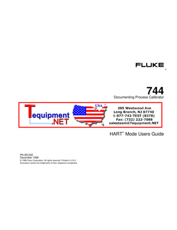
744HART Mode Users GuideThe Active Device screen provides the followinginformation for all transmitters, supported or generic:pe06s.bmp4 Poll address (if not 0)Model number and Tag IDPV (Primary Variable)PVAO (digital representation of the Analog Output)PV LRV (PV Lower Range Value)PV URV (PV Upper Range Value) Softkeys for accessing HART operation menus
Documenting Process Calibrator HART ModeConnecting to a HART Transmitter744MEASSOURCE7495-PS PSM-IN INSETUPCLEARSZ( CUMENTING PROCESS VMAXTCpe01c.epsFigure 1. Connecting to a HART Transmitter5
744HART Mode Users GuideSupported vs. Generic TransmittersThe calibrator communicates with virtually all HARTtransmitters. In addition, the calibrator is programmed touse device-dependent commands for a selection of HARTtransmitters and their software versions. These are“supported transmitters.” All other transmitters are“generic.”2.If the calibrator is not connected to a HARTtransmitter, press the r key followed by MoreChoices.3.Press the Device Revs softkey. The Browser screenappears.Table 1 shows the operations that are available forsupported vs. generic transmitters in single point andmultidrop configurations.NoteSensor trim is provided for supportedtransmitters, with a few exceptions, as identifiedin the list of supported transmitters that you canview on the display.pe07s.bmp4.Press u or d to highlight the desired manufacturer,and press e. A list of model numbers appears.5.Press u or d to highlight the model number, andpress e. A list of software versions appears.To display a list of supported transmitters and softwareversions:1.6If the calibrator is connected to a HART transmitterwith the Active Device screen showing, press theAbort softkey, followed by More Choices.
Documenting Process Calibrator HART ModeSupported vs. Generic TransmittersTable 1. Supported vs. Generic Transmitters (Devices)MenuOperationSupported TransmitterGeneric TransmitterSingle PointMultidropSingle PointMultidropTop LevelActive Device screen SetupBasic (read/write, cloning capability) Sensor (read only) Device Identification (read/write) HART Output (read/write) HART Information (read only) Loop Test Not Available Not AvailablePressure Zero Trim Output Trim Not Available Not AvailableSensor Trim Not AvailableNot AvailableDetailed process information ServiceProcess7
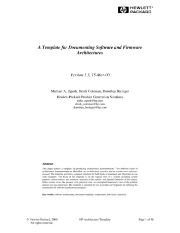
744HART Mode Users GuideCommunication OperationsSetup OperationsFigure 2 shows the HART Mode menu tree. Availability ofsome elements in the menus depends on whichtransmitter you are using, and whether the transmitter isconfigured by itself on a current loop or in a multidropconnection.The Setup softkey provides access to the following fivesetup functions:Viewing Process VariablesFrom the Active Device screen press the Process softkeyto view more device variables and their continuouslyupdated values. To see additional information, press theNext Page softkey. BasicSensorDevice IdentificationHART OutputHART InformationBasicFrom the Active Device screen press the Setup and Basicsoftkeys to access the read/write Basic Setup screen. Youcan use this screen to clone a transmitter as described atthe end of this manual.pe08s.bmppe09s.bmp8
Documenting Process Calibrator HART ModeCommunication OperationsPROCESS(Example)PV% RangeAOSV, TV, QVBasic TagPV unitsLRV, URVDampingTransfer function Software versionFinal assembly icationSETUPLoop testSERVICEHARTOutputPressurezero trimOutput trimSensor trimHARTInformation ManufacturerModelDevice HART IDSoftware revisionHardware revisionNumber of preambles Sensor serial numberSensor lower andupper limits Sensor minimumspan(temperature devices only) Sensor type Sensor connections Write protectAlarm stateHART poll addressHART burst modeHART burstcommandABORTpe03f.epsFigure 2. 744 HART Mode Menu Tree9
744HART Mode Users GuideSensorDevice IdentificationFrom the Active Device screen press the Setup andSensor softkeys to access the read-only Sensor Setupscreen. This is where you can view information about thesensor in the transmitter, including serial number, limits,and span. The limits shown are the absolute limits for thesensor. (The Upper Range Value (URV) and LowerRange Value (LRV) are different, and are viewable andprogrammable through the Basic Setup screen.)From the Active Device screen press the Setup andDevice Identification softkeys to view information about thetransmitter. You can program the Tag, Message, Date,and Descriptor registers in the transmitter using thisscreen.pe11s.bmppe10s.bmp10
Documenting Process Calibrator HART ModeCommunication OperationsHART OutputHART InformationFrom the Active Device screen press the Setup and HARTOutput softkeys to access the read/write HART OutputFrom the Active Device screen press the Setup and HARTInformation softkeys to access the read-only HARTscreen. Here you can change the Poll Address (0 singletransmitter, any other address multidrop), and controlburst mode.Information screen. This screen shows more completeinformation about the transmitter model, hardware andsoftware revision numbers, and how many preambles itsends.pe12s.bmppe13s.bmp11
744HART Mode Users GuideService OperationsThe Service softkey provides access to Loop Test,Pressure Zero Trim (where applicable), Output Trim, andSensor Trim operations. For generic transmitters, onlyLoop Test, Output Trim, and Pressure Zero Trim areavailable. (See Table 1.) The trim (adjustment)operations are described later in this manual.NoteLoop Test and Output Trim are not available ifthe transmitter is in multidrop mode.Interaction between Analog Mode andHART ModeAnalog mode is normal calibrator operation, as describedin the 744 Users Manual. HART mode is activated whenyou press the r (HART) key. This action startscommunication over the HART interface.You can switch between HART and analog modes easilyby pressing r (or pressing M to go to analog modefrom HART mode), gaining the benefit of having thetransmitter automatically,set up analog mode forappropriate measure and source functions, if desired.Abort SoftkeyThe Abort softkey terminates the communicationoperation underway, and returns control to the previousscreen. From the Active Device screen, Abort calls up thebrowser, in which you can view the list of supportedtransmitters.For supported transmitters, the transition to analog modegoes to the MEASURE/SOURCE screen, which providesan easy way to proceed with an “as found” calibration.For generic transmitters, the transition to analog modeinvolves choosing the MEASURE or SOURCE screen,from which you select the appropriate function.For supported or generic transmitters, when you pressr to return to HART mode, the Active Device screen isdisplayed. The HART serial communication connectionremains active as you switch between HART and analogmodes.12
Documenting Process Calibrator HART ModeUnderstanding HART CalibrationUnderstanding HART Calibration744 HART Mode Menus for AdjustmentAn analog transmitter has one stage of electricalconversion from a measured physical parameter to a4-20 mA current loop output. A HART transmitter has thethree stages shown in Figure 3.In 744 HART mode, adjusting the Input stage is calledSensor Trim. Adjusting the Output stage is called OutputTrim. Both adjustments are made from the Service menu.Depending on how the transmitter is used in y
Information in the 744 Users Manual before you use the Fluke 744 Documenting Process Calibrator. With analog transmitters, you must make a hardware adjustment during calibration. With HART (Highway-Addressable Remote Transducer) transmitters, adjustments are by remote command. These adjustments require the use of a communication tool as well as a calibrator. The Fluke 744, hereafter called .


![[Final] Documenting the University of Pennsylvania’s .](/img/9/csgraubard-documenting-the-university-of-pennsylvanias-connection-to-slavery.jpg)