Transcription
LOW COST INERTIAL NAVIGATION:LEARNING TO INTEGRATE NOISEAND FIND YOUR WAYByKEVIN J. WALCHKOA THESIS PRESENTED TO THE GRADUATE SCHOOLOF THE UNIVERSITY OF FLORIDA IN PARTIAL FULFILLMENTOF THE REQUIREMENTS FOR THE DEGREE OF MASTER OF SCIENCEUNIVERSITY OF FLORIDA2002
ACKNOWLEDGMENTSThe research conducted in this thesis could not have been accomplished without thehelp of the Machine Intelligence Lab and the Autonomous Submarine Team at the University of Florida who donated the use of their IMU. Their support was of great help.Special thanks go to Dr. David Novick and Dr. Paul Mason. Both of these individualsalways provided me with a sounding board to bounce my ideas and concerns off of. Theyalso provided me with an indispensable wealth of information, knowledge, understanding,and friendship. For that alone I will always be grateful.Last, but not least, I would like to thank my loving wife, Nina Walchko, and our packof wild cats. They suffered with me through the hard times and long hours, but werealways there to help cheer me up when I needed it.ii
TABLE OF CONTENTSpageACKNOWLEDGMENTS . iiLIST OF TABLES . viLIST OF FIGURES . viiABSTRACT.x1INTRODUCTION .1Inertial Navigation .1Previous Work .2Thesis Outline .42WHERE IN THE WORLD IS WALDO .5GPS Network Overview .5How GPS Works .6NMEA Messages .6WGS-84 .7Grids .7Accuracy .8Differential GPS .103INERTIAL NAVIGATION .12Overview of Inertial Navigation Systems .12Gimballed INS .12Strap-down INS .13Reference Frames and Rotations .13Modelling the Earth .16Position on the Earth’s Surface .16Gravity Model .17Navigation Equations .17iii
Position and Velocity .17Attitude .19Summary of Navigational Equations .224CORRECTING INERTIAL NAVIGATION .23Sources of Error .23Bias and Drift .23Temperature .24Hysteresis .24Vibrations .25Extended Kalman Filter .25Position Error Model .26Attitude Error Model .27Summary of Error Model Equations .295HARDWARE AND EXPERIMENTAL SETUP .31Standard IMU Hardware .31Gyroscopes .31Ring Laser Gyro (RLG) .31Fiber-Optic Gyros (FOG) .32MEMS .32Hardware Used .35Crossbow IMU .35IMU Performance .36Prefiltering IMU Data .38Garmin GPS .39Experimental Setup .406RESULTS .41Navigational Solution Only .41GPS/INS .427CONCLUSIONS .49A ATTITUDE REPRESENTATIONS AND ROTATION MATRICES .50Fixed Angle Rotations .50Euler Angles .51iv
Quaternions .53Quaternion Algebra .54Rotations of Rigid Bodies in Space. .56Attitude Errors in Quaternions .57Summary of Quaternions .58B KALMAN FILTERING AND ESTIMATION .59Introduction .59Kalman Filter Theory .60Implementing The Kalman Filter .62Extended Kalman Filter Design .64Augmented Kalman Filter .65Estimation Models .66Controllability and Observability of the Kalman Filter .66Controllability .67Observability .67REFERENCES .68BIOGRAPHICAL SKETCH .70v
LIST OF TABLESTablepage2-1. Accuracy of GPS 95% of the time. .103-1. Coordinate system subscripts and superscript definitions. .143-2. Earth model constants (WGS 84) .164-1. Positional errors .235-1. Data conversions for the Crossbow IMU. .355-2. IMU prefilter specifications. .386-1. Distances traveled as reported by the different systems. .446-2. Distances traveled as reported by the different systems. .46A-1. Properties of a rotation matrix. .51A-2. Comparison of the two major types of rotations .52A-3. Quaternion Algebra Summary .54B-1. Description of kalman filter variables. .63B-2. Various models used in the kalman filter. .66vi
LIST OF FIGURESFigurepage1-1. Boeing conversion kit which transforms a standard gravity bomb into a smart bomb. .32-1. Orbits of GPS network. .52-2. Standard GPS satellite in orbit. .52-3. An airplane receiving a 3D position from 4 GPS satellites. .82-4. How the UTM breaks up the surface of the world. .82-5. WAAS coverage areas. Currently only the Pacific (pink) and Atlantic (yellow)satellites are up and running. .113-1. A flow chart of a strap-down INS which takes accelerations and rotation rates fromthe IMU and produces position, velocity, and attitude of the system. .133-2. The XYZ frame is the inertial frame ECEF and the NWU frame is the localnavigational frame, where the axes are north, west, and up. .153-3. Body frame which is aligned with the axes of the IMU. The center of this frame islocated at the origin of the navigational frame. .154-1. Overview of the extended kalman filter’s integration with the INS. .255-1. Ring laser gyro shown at top (note the triangular shape) and fiber-optic gyro diagramshown below. .325-2. Spider mites walking on some MEMS parts. .345-3. MEMS IMU. .345-4. MEMS thrusters. .34vii
5-5. Sensors used in the INS. (left) The Crossbow DMU-HDX which is a solid statevertical gyro capable of measuring angular rates and accelerations on all threeaxes. It also has the capability of measuring the roll and pitch of the device too.(right) Garmin 16LVS OEM GPS which is both a receiver and antenna. .345-6. Change in accelerometer reading over time due to temperature change. .375-7. Random movement of system due to hysteresis. .375-8. This is a plot of the biases as the IMU was rotated around the z-axis (yaw). Rotationsaround the other axes would also effect the biases, thus this mapping is notuseful since the values are changing nonlinearly. .385-9. Comparison of the unfiltered data (top) produced by the IMU and the filtered data(bottom) using the Chebyshev II filter. .385-10. This is a test of the GPS accuracy. The GPS was set in a stationary location for 4hours. The center of the plot was taken to be the average latitude and longitudereported by the sensor. Then the corresponding distances from the average werecalculated. This GPS receiver is capable of providing the standard 10 meteraccuracy 95% of the time. .396-1. Map of the entire route taken from www.mapquest.com .416-2. Number of satellites seen by the GPS receiver during the test. .416-3. INS attitude solution with out extended kalman filter. .426-4. INS results without GPS and kalman filter integrated into the system. .436-5. INS results with GPS and kalman filter integrated into the system. .436-6. This plot shows the interpolating capabilities of the INS system in X and Y.435-7. This plot shows the interpolating capabilities of the INS system in Z. .435-8. Route taken for second test: starting at the commuter parking lot take North-SouthDrive, Archer Road, 34th Street, University, and back. .455-9. Results from the INS which match good with the map of the route. .455-10. Corner of Archer Road and 34th Street. .455-11. The GPS data and INS solution for one of the stoplights on Archer Road. .46viii
5-12. The results from driving through a parking garage which blocks the GPS signal. TheINS solution is shown on the left while the GPS readings are shown on the right.The location of the parking garage and the correct path are drawn on the plots. .475-13. Number of satellites seen during the experiment. .47A-1. Body reference frame attached to a rigid body. .51B-1. Kalman filtering process at work, taking noisy input measurements and producingfiltered output measurements. .64ix
Abstract of Thesis Presented to the Graduate Schoolof the University of Florida in Partial Fulfillment of theRequirements for the Degree of Master of ScienceLOW COST INERTIAL NAVIGATION:LEARNING TO INTEGRATE NOISEAND FIND YOUR WAYByKevin J WalchkoAugust 2002Chair: Dr. Mike NechybaMajor Department: Electrical and Computer EngineeringNavigation is becoming more common in all areas of industry and commercial sectors.The main tool being utilized is GPS. However there are situations in which higher levelsof accuracy are required which can not be achieved by GPS alone. This thesis will discussthe design and implementation of an inertial navigation system (INS) using an inertialmeasurement unit (IMU) and GPS. The INS is capable of providing continuous estimatesof a vehicle’s position and orientation. Typically IMU’s are very expensive sensors; however this INS will use a “low cost” version costing around 5,000. Unfortunately with lowcost also comes low performance and is the main reason for the inclusion of GPS into thesystem. Thus the IMU will use accelerometers and gyros to interpolate between the 1HzGPS positions. All important equations regarding navigation are presented along with discussion. Results are presented to show the merit of the work and highlight various aspectsof the INS.x
CHAPTER 1INTRODUCTIONNavigation has been present for thousands of years in some form or another. Thebirds, the bees, and almost everything else in nature must be able to navigate from onepoint in space to another. For people, navigation had originally included using the sun andstars. Over the years we have been able to develop better and more accurate sensors tocompensate for our limited range of senses. This thesis will discuss work using one ofthese advanced sensors, an inertial measurement unit (IMU). This sensor, coupled with theproper mathematical background, is capable of detecting accelerations and angular velocities and then transforming those into the current position and orientation of the system.Inertial NavigationUnfortunately Inertial Navigation Systems (INS) have been relegated to the realm ofmilitary applications due to the extreme cost of the systems. High precision componentsmust be incorporated into the IMU to produce good results. The most critical are thegyros, which are used to determine the orientations of the system. The orientation is critical to properly account for gravity. If gravity is accounted for in the accelerometer readings, then the system thinks it is moving when in fact it is not. Also high qualityaccelerometers are important. Ideally their should be no bias (or very low at least) andbehave in a simple linear fashion. Unfortunately in real life, noise, disturbances, drifts,misalignments, and manufacturing complications enter into the equation and make developing an INS difficult.1
2If INS is so expensive, how do you create a low cost solution? The saving grace of lowcost INS is the Global Positioning System (GPS). This system provides accuracies of 10 m95% of time at an update rate of 1 Hz. The receiver only costs 100- 200 depending onsize, features, etc. This system now provides a way to bound the errors in an INS and theuse of lower cost components in the IMU. Thus cheap but accurate INS systems can bedeveloped for all sorts of applications that previously were cost prohibitive (i.e. consumercars, remotely controlled vehicles, autonomous vehicles, military munitions, etc).Previous WorkINS’s have been developed for a wide range of vehicles. Sukkarieh [1] developed aGPS/INS system for straddle carriers that load and unload cargo ships in harbors. Whenthe carriers would move from ship to ship, they would periodically pass under obstructions that would obscure the GPS signal. Also, as the carriers got closer to the quay cranes,it became more difficult to get accurate positions due to the GPS signal being reflectedabout the crane’s metal structure. This increases the time of flight of the GPS signal andresults in jumps in the position. During these times the INS would then take over, andguide the slow moving carrier until a reliable GPS signal could be acquired.Mandapat [2] developed a low cost INS for Dr. Carl Crane here at University of Florida to replace their current system which is highly accurate, but very expensive. The current system is the Honeywell Modular Azimuth Positioning System (MAPS) and AshtechZ-12 Differential GPS. This system has an accuracy of less than 10 cm at a data rate of 10Hz. The new system uses an IMU also developed from Honeywell which has ring lasergyros and costs about three times the IMU used in this work. Mandapat’s GPS/INS produced positional errors within 1 to 2 meters of the MAPS system at a fraction of the cost.
3Bennamoun et al. [3] developed a GPS/INS/SONAR system for an autonomous submarine. The SONAR added another measurement to help with accuracy, and provided apositional reference when the GPS antenna got submerged and could not receive a signal.Ohlmeyer et al. [4] developed a GPS/INS system for a new smart munitions, the EX171. Due to the high speed of the missile, update rates of 1 second from a GPS only solution were too slow, and could not provide the accuracy needed. The GPS/INS smart munitions are cheaper than their more accurate cousins, Laser Guided Munitions (LGM). Theyare also immune to conditions which can greatly deteriorate the accuracy of LGM, such asbad weather, heavy dust/snow storms, and fog. This integration of GPS/INS is a growingtrend for military munitions (i.e. bombs, missiles, artillery shells, remotely operated vehicles). Boeing [5] has developed a GPS/INS kit that converts old gravity bombs into precision-guided smart bombs. A control unit is attached to the end of the warhead whichcontains the GPS/INS system and battery powered motors to control the flight of thebomb. Actual use by American aircraft in Afghanistan during the 2002 War on Terrorismproved these bombs can strike within 13 meters of their intended target.Figure 1-1. Boeing conversion kit which transforms a standard gravity bomb into a smartbomb.
4Thesis OutlineThe remainder of this thesis will flow as follows. Chapter 2 will discuss GPS andfamiliarize the reader with how it works. Chapter 3 will introduce all of the key conceptsfor inertial navigation and derive all important equations. Chapter 4 will introduce problems inherent in inertial navigation and provide the necessary background for theextended kalman filter used which will aid in correcting these errors. Chapter 5 will provide background on hardware used in inertial navigation and the IMU and GPS that wereused in this work. Chapter 6 will cover the experimental setup and present results usingthe developed INS. Various aspects of the INS’s performance will be presented to show itsmerit. Finally chapter 7 will present the conclusions drawn from this work.
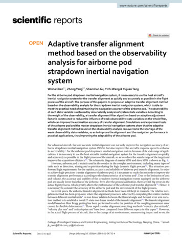
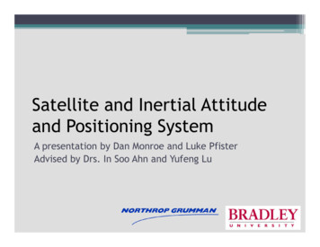
CHAPTER 2WHERE IN THE WORLD IS WALDOThis chapter will give an overview of the global positioning system (GPS). The purpose is to provide the reader with the basic fundamental understanding of how GPS worksand some of the technologies involved. Most of the information in this chapter comesfrom three sources: Dr. Peter H. Dana [6], Garmin Users Manual [7], and Federal AviationAdministration (FAA) [8].GPS Network OverviewThe GPS network of satellites contains a minimum of 21 satellites that orbit the Earthat an altitude of about 11,000 nautical miles. They orbit once every 11 hours and 58 minutes, so that they drift in the sky 4 minutes a day (they drift 2 minutes each orbit). Thereare 6 different orbits that the satellites can be in, with multiple satellites in each orbit. Eachpossible orbit is inclined 55 degrees with the equator with no orbits going directly over thepoles.Figure 2-1. Orbits of GPS network.Figure 2-2. Standard GPS satellitein orbit.5
6How GPS WorksFinding your location using GPS is accomplished by triangulating your position fromthe known positions of GPS satellites. Distance measured from your position to the satellite is measured by time of flight of a signal sent from the GPS satellite. The signal sentfrom the satellite tells its location and the time the signal was sent. Since the signal travelsat the speed of light, the distance from the receiver to the satellite can be calculated. Witha GPS receiver and one satellite, you can determine your possible location on a spherewith the satellite at the center. Unfortunately this is not very useful. With two satellites weget two spheres that are centered at different locations. Now our position lies at the intersection of these two spheres, which is a circle. Unfortunately this is still not useful. Nowexpanding the our network of satellites to three and a third sphere we get two possiblelocations the receiver can be in 3D space. Immediately one of the two possible solutionscan be discarded, leaving us with our position. Thus with three satellites, we can easilydetermine our position in 3D space. But this now raises the question, how accurately canwe calculate this position? This question will be answered in the next section which covers accuracy.NMEA MessagesThe signals or messages that are sent from the satellites are defined by the NationalMarine Electronics Association (NMEA). This group has defined standards for just aboutevery possible device used for navigation and instrumentation. In fact the standardsdefined for use with GPS actually define not one, but many different messages designed toprovide every possible piece of useful information. NMEA also allows hardware vendorsto define their own proprietary messages. An example sentence might look like:
7 ,M,46.9,M,,*42Listing 2-1. Meaning of example NMEA message fields GGA1235194807.038,N01131.000,E1Start character of messageGlobal Positioning System Fix DataFix taken at 12:35:19 UTCLatitude 48 deg 07.038’ NLongitude 11 deg 31.000’ EFix quality: 0 invalid1 GPS fix2 DGPS fix08Number of satellites being tracked0.9Horizontal dilution of position545.4,MAltitude, Meters, above mean sea level46.9,MHeight of geoid (mean sea level) above WGS84 ellipsoid(empty field) time in seconds since last DGPS update(empty field) DGPS station ID number*42The checksum data, always begins with *The current NMEA standard is 0183 version 2.0 which transmits data at 4800 baud.WGS-84There are hundreds of datum that have been defined all over the world and through outthe years. Some of these datums are regional (such as the US datums NAD27 CONUSused by the USGS and NAD83 or the European 1979) and some are global (such as theWGS72). The World Geodetic System (WGS-84) is a world wide datum with its originlocated at the center of the Earth and defines a reference ellipse. The reference ellipse isitself defined by the major and minor axes of the Earth, which were determined by examining all known data in 1984. The data came from every possible source including satellies. This is the datum which GPS uses to determine altitude above the reference ellipse.GridsNow that we had defined a datum for out coordinate system, we need to be able todivide the world up into nice pieces. Most people are familiar with latitude and longitudewhich accomplish this division of the world. However the problem with this system is that
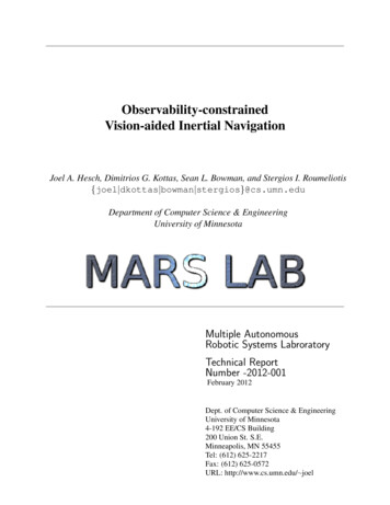
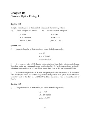
8Figure 2-1. An airplane receiving a 3D Figure 2-2. How the UTM breaks up theposition from 4 GPS satellites.surface of the world.the world is round and not an nice even sphere. Navigation has defined one nautical mileas 1 minute of latitude along the equator. Since there are 60 minutes to each degree, thereare 60 nautical miles per degree of latitude. The problem occurs as we increase our longitude, the distance between lines of latitude decrease. Thus at 45 degrees longitude thereare only 42.426 nautical miles. GPS uses a more precise system called the Universal Tansverse Mercator (UTM). This divides the world up into 60 slices with minimal distortioncompared to the traditional latitude/longitude system (an example of this is shown in Figure 2-2).AccuracyTime is a critical value in the equations that need to be solved to determine thereceiver’s position in 3D space (to well under a micro-second). Each satellite in the GPSnetwork that orbits the Earth is equipped with an atomic clock so that they know exactlywhen they send a signal (which is encoded in the signal itself using a pseudo-random signal of 1023 bits). Unfortunately these clocks are very large and expensive. Thus it would
9not be feasible to embed these into every receiver on the market. So a compromise wasmade to include more inexpensive clocks into the receivers, but instead of treating time asa known in the GPS equations, it becomes a variable. Thus now a fourth satellite isrequired to reach a solution for the receiver’s 3D position. The assumption is also madethat any error in the system comes from our clock being in error (which is an incorrectassumption). Thus the time variable can be changed to reduce the error in the solutionsfrom the four satellites (Figure 2-1).Once the data is collected from the satellites, a set of 7 simultaneous equations andunknowns are solved. The unknowns are positions (x, y, z), doppler (dx, dy, dz), and time.Proprietary methods
Typically IMU's are very expensive sensors; how-ever this INS will use a "low cost" version costing around 5,000. Unfortunately with low cost also comes low performance and is the main reason for the inclusion of GPS into the system. Thus the IMU will use accelerometers and gyros to interpolate between the 1Hz GPS positions.