Transcription
DSG-200ELECTRIC ACTUATORSAN ISO 9001 COMPANYMADE IN THE USASINCE 1936HAROLDBECK.COMIMPROVING INDUSTRIAL CONTROL SINCE 1936
THE HISTORY OFM A K I N G B E C K A C T U ATO R SSince 19361936 - 1942Later that same year, a biggerbasement became necessary. The QG %(&. HDGTXDUWHUV W. Mt Airy Ave, Philadelphia,PA.1936Where it allbegan. Harold%HFN̄V &KHϟQXW Hill basement.2XU )RXQGHU DUROG & %HFN,QYHQWRU (QWUHSUHQHXU1942%(&. EHFRPHV LQWHJUDO WR WKH ZDU HϙRUW KHOSLQJ WKH ϟHHO DOXPLQXP LQGXϟULHV NHHS SDFH ZLWK VN\URFNHWLQJ GHPDQG .HHSLQJ SDFH UHTXLUHG D PRYH WR %(&.̄V ϚUϟ IDFWRU\ : 'XUKDP 6W 0W LU\ 6HFWLRQ RI 3KLODGHOSKLD
1970 Present%(&.̄V WK DQG SUHVHQW ORFDWLRQ 7HUU\ 'U Newtown, PA.yet more space was1945 AndUHTXLUHG TO DAYSTILL SERVING INDUSTRYStill Made in the U.S.A.
4
TABLE OF CONTENTSIntroduction. 7Process Control Improvement. 8Rotary ActuatorsAvailable in a range of torque outputs from 15 to 8,000 lb-ft. Linkage kits, pedestalsand valve hardware are available for easy field mounting to final control elements.Model Group 11. 11Damper and quarter-turn valve actuatorsModel Group 22.25High torque damper actuatorsModel Group 31.33Compact actuators for low torque damper and valve applicationsModel Group 57.41AC/DC powered quarter-turn valve actuatorsModel Group 75.47Special purpose actuators for windbox dampers and small valve applicationswhere heat, space and access is an issue.Linear ActuatorsAvailable with a range of stroke options from 5/16" to 18", custom hardware isavailable for easy field mounting to final control elements.Model Group 14.57Providing up to 4,000 lbs. of thrust, these actuators incorporate a uniquedesign feature that ensures tight shut-off at the end of travel—commonlyused on globe valve applicationsModel Group 29.65Providing up to 6,100 lbs. of thrust, these actuators incorporate a uniquedesign feature that ensures tight shut-off at the end of travel—even inhazardous locationsModel Group 42.73Long stroke actuators providing up to 1,000 lbs. of thrust, ideally suited forburner air register type applicationsSpecialty Applications. 82Beck electric actuators are available to improve the efficiency of almost anyprocess; including multi-rev drives, burner tilt units, fluid couplings, magneticcouplings, material flow gates and pump handle valves.Accessories / Services. 84Beck offers a wide range of accessories and services to meet all of your actuationneeds; including installation assistance, various options, linkage kits, hazardouslocation ratings, site surveys and spare parts planning. Beck also offers remotelylocated electronics for extreme application sites, remote indication and/or controlstations and a back-up power option.5
6
INTRODUCTIONScanforVideoBeck's reliability, unique design and expert assistance will help you meet yourprocess control objectives.INDUSTRY’S CHOICE FOR PRODUCT ANDSERVICE EXCELLENCEUniquely designed Beck electric actuatorsoffer constant, precise control without theperformance and maintenance limitationsof typical actuators. Unlike pneumatic andconventional electric actuators, Beck actuatorscan withstand continuous duty modulationwithout degradation of performance. Ourunique electric actuators combine thepositioning necessary for optimum control withthe reliability to keep the process running. Unique, no-burnout motor allows continuousmodulation Easy drop-in installation Factory calibrated smart digital controlelectronics Virtually maintenance-free Three year warrantyBeck has an electric actuator for mostindustrial control applications and, with over80 years of industrial actuation experience,we have the know-how to ensure an excellentsolution to your actuator needs.Industries ServedBeck actuators provide precise, reliablepositioning of valves, dampers, fluid couplingsand other final control elements. Below is a listof just some of the industries that depend onBeck actuators: Wood products Electric power Cement and lime Pulp and paper Water and wastewater treatment Glass Minerals Chemical/petrochemical Steel Refineries Aluminum and other metals Food and beverageFor more detailed information regarding ourindustrial applications, visit our website:http://www.haroldbeck.com/industries.htm7
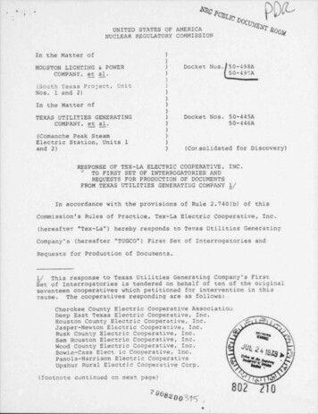
PROCESS CONTROL IMPROVEMENTEngineered to the High PerformanceStandards of Today’s SophisticatedControl Instrumentationreal performance improvements will only berealized if the final control element is up tothe task. Frequently, the inconsistent andsluggish performance of pneumatic actuatorsor the unreliability of typical electric actuatorsis the limiting factor in the performance of thecontrol loop. Therefore, when it is necessaryto improve process control performance, thefirst step is to improve final control elementperformance.To fully utilize the power and performancecapabilities of today’s process controlinstrumentation, the final control elementmust be positioned quickly, precisely andconsistently. Beck electric actuators provideinstantaneous response with the precision andrepeatability necessary to fully utilize controlsystem capabilities.Beck actuators maximize final controlelement performance, providing responsive,repeatable actuation. Beck's unique design—incorporating a no-burnout motor, efficient spurgearing and accurate, durable electronics—enables the Beck actuator to start and stopinstantly, virtually eliminating dead time andovershoot regardless of load or processconditions.As the emphasis in industry continuesto focus on improved quality and efficiency,and as environmental pressures continue toexpand, the need for improved process controlperformance will also continue to broaden.Industry will continue to make large capitalinvestments in state-of-the-art instrumentationand advanced control technologies. However,DEMAND AND POSITION vs. TIME52.552POSITIONPERCENT OF SPAN51.5Figure 1-15150.5Pneumatic actuatorresponse to a 2%ramping demandDEMAND5049.54948.5020406080100120TIME, secondsDEMAND AND POSITION vs. TIME52.552PERCENT OF SPAN51.5DEMANDPOSITIONFigure 1-251Beck actuatorresponse to a 2%ramping demand50.55049.54948.50204060TIME, seconds880100120
More Consistent and Precise thanPneumaticsMore Reliable than Conventional ElectricActuatorsBeck actuators eliminate the performancebottlenecks created by inconsistent andnonlinear pneumatic actuator performance,which typically varies as a function of frictionaland dynamic load, process conditions, thecondition of the valve or damper and theperformance of actuator accessories such asI/P transducers, regulators and positioners.Unlike pneumatic actuators, Beck actuatorsprovide consistent and repeatable positioning.Beck actuators incorporate a no-burnoutmotor, an efficient spur gear drive trainand accurate, durable electronics. Thisunique design eliminates the performancelimitations typical of electric actuators,including overheating motors, trips, worm gearwear-induced backlash, coasting and otherpositioning inaccuracies.Beck-built motors are specifically designedto provide instant acceleration and decelerationfor extremely precise positioning in modulatingapplications. These reliable motors do not burnout or overheat even under the demandingconditions of an active control loop.Figure 1-1 shows the response of apneumatic diaphragm valve actuator to a2% ramping demand signal representativeof a control signal modulating the valve. Theresponse demonstrates actuator dead timeand overshoot often referred to as “stick andslip.” It is not unusual for stick to completelyprevent actuator response to the small demandchanges typical of continuous process control.Figure 1-3 illustrates the cool, stableoperation of the Beck motor in comparison withconventional single-phase and three-phasemotors. Tests were conducted under a 100%duty cycle to simulate maximum control loopactivity. The temperature in the conventionalmotors quickly rose to a dangerous level,tripping the thermal overloads, rendering themotor unavailable for control.Figure 1-2 shows the response of a Beckelectric actuator to the same demand. TheBeck actuator tracks the demand closely,eliminating dead time and the significantovershoot associated with the pneumaticactuator. This type of performance gain in theactuator could be the difference between anuncontrollable flow loop and a tightly controlledone.Motor Temperature RiseActive Control Loop120110100Temperature ( C)Throughout this brochure, the phrase“continuous operation” refers to the actuator’sability to operate continuously when requiredfor accurate process control, especially duringstart-up, load changes and process upsets.However, excessive modulation due to processnoise, electrical control signal noise, or controlsignal aliasing will shorten the life of theactuator as well as the valve or damper. Forthis reason, the control loop should be properlyanalyzed and tuned to avoid excessive orunwarranted modulation.The Beck motor, in contrast, slowly rose intemperature under these service conditions,remaining stable and continuously availablefor process control.Conventional Motor - Abrupt Loss of 06050020406080100120140160180Time (minutes)Figure 1-3Cool, stable operation of the Beckcontrol motor9
10
GROUP 11DAMPER & QUARTER-TURN VALVE ACTUATORSAccurate, dependable control for a wide variety of applications.Beck Group 11 electric actuators provideprecise, consistent modulation of all types andsizes of dampers and valves. Unlike traditionalelectric actuators, Beck actuators have no dutycycle limitation and can continuously modulatewithout overheating.Beck actuators have the unique abilityto quickly, accurately and consistently trackthe control signal. This ability significantlydecreases process variability—improvingproduct quality and reducing operating costs.Beck has eliminated the problems associatedwith pneumatic actuators such as stick-slipresponse, inconsistent performance and airquality issues. Virtually maintenance-free anddesigned for harsh industrial environments,Beck will drastically reduce your maintenancecosts while improving your process control.Beck Group 11 damper drives are equippedwith a specially engineered crank arm. Customlinkage arrangements are available.Beck Group 11 valve actuators areengineered for direct-coupling on quarter-turnball, plug and butterfly valves. They may alsobe installed using specially engineered crankarm and linkage arrangements.Valves and actuators may be orderedtogether as pre-engineered assemblies readyfor drop-in installation; or actuators can besupplied separately along with the necessaryhardware for field installation on existingvalves.11
FEATURESDigital ControlModule (DCM)Wiring Terminal BlockCrankArm &LinkageOver-travelLimit andAuxiliarySwitchesBeck MotorPrecise, Reliable ControlTogether with Beck’s control electronicsand rugged gear train, Beck motors providethe precise, reliable positioning required formodern control loops. Never overheats or burns out, even underdemanding modulating control or stalledconditions. Reaches full speed and torque in lessthan 50 milliseconds and stops within 25milliseconds, eliminating deadtime. Provides extremely accurate positioning inmodulating applications. Will not coast or overshoot the desiredposition.Gear Train /MotorPositionSensingDevice (CPS)Digital ControlModule (DCM)Over-travelLimit andAuxiliarySwitchesHandwheelValveMounting Maintenance-free with double-lipped, greasesealed bearings.Electric HandswitchMotorPositionSensing Device(CPS) Low current draw of 0.17 A to 3.0 A, andtherefore low power consumption, eliminatesthe need for relays and permits the use ofuninterruptible power supplies.Time-Saving Local OperationDampers or valves may be operatedat their individual locations with the built-inelectric Handswitch. This saves time duringinstallation and troubleshooting, allowing onlineadjustments to be made quickly and easily bybypassing the electronics in the actuator andcontrol system.The Handswitch also serves as an electricalbackup in the event of control system failure.WiringTerminalBlockAuxiliary and Over-travel Limit SwitchesTwo over-travel protection limit switchesare provided. Up to four auxiliary switches areavailable. Optional switch features: SPDT switches rated for a minimum of 6 A at120 Vac, (three times maximum motor currentfor most models) to ensure long life. Field-adjustable to operate at any point in theactuator’s travel range. May initiate secondary functions or provideremote indication of actuator position.Group 11 Components12 Eliminates unreliable and maintenanceintensive proximity switches.
Drive TrainPower and Durability to Maximize ControlAvailabilityBeck’s durable gear train maintains accurate,consistent control element positioning even underthe demanding conditions of an active control loop. Gear trains employ a unique, all spur gearconstruction of heat-treated alloy steels andductile iron. Efficient, wide-face spur gearing essentiallyeliminates wear-induced backlash andpositioning inaccuracies. Durable design provides up to 4 days ofprotection against intermittent or extendedaccidental stalls. Individual compartments protect all majorcomponents: Motor, DCM, CPS, gear trainand installation wiring terminal board. Each compartment can be accessed withoutexposing other components. Gasketed, precision-machined coversprovide extra protection for harsh indoor andoutdoor environments. Output and Handwheel shafts are also sealedwith weatherproof, double-lip seals.Mounting VersatilityBeck Actuators can be Mounted in anyOrientation for Greater Installation Flexibility Integral self-locking mechanism ensuresthat drives hold a minimum of 200% of ratedtorque with the motor de-energized.Beck actuators are configured and lubricatedin such a way that they may be mounted inany convenient position. This flexibility allowsactuators to be installed in hard-to-fit locations.Manual HandwheelIf housing compartments are accessible,there are no mounting orientation limits.Convenient Manual Control Without DeclutchAn easy-to-turn, spoke-free Handwheel isincorporated into the Group 11 design to allowmanual operation during installation or poweroutages. Handwheel can be used to move valves anddampers to any position smoothly and easilyunder full load conditions. Mechanical stops in housing prevent manualovertravel. The motor operates at 72 or 120 RPM, so theHandwheel poses no safety hazard.HousingSuperior Protection and ConvenientAccess to ComponentsBeck actuators feature a cast aluminumbody with individual compartments to protectcomponents from moisture and dirt, and alloweasy access for installation and calibration. Precision-machined aluminum alloy castingswith corrosion-resistant poly-urethane paintprovide a rugged, dust-tight, weatherproofType 4X enclosure. Models approved foruse in Hazardous classified locations areavailable—contact a Beck Sales or ApplicationEngineer for details.Mounting ArrangementsDirect-Coupled ConfigurationsA factory machined coupling is used toconnect the actuator directly to the valve. Thisconfiguration is compact in design and is idealfor applications where a constant torque isdesired over the full 90º range of travel.Crank Arm / Linkage ConfigurationsValve / actuator assemblies may bespecified with crank arm and linkage mountingarrangement. This design allows 100º actuatortravel, thus providing variable torque distributionand increased seating effectiveness. With linkage characterization, high seatingtorques can be obtained for certain valvetypes. Standard bracket and linkage mountinghardware is available for most popular valvetypes. Custom mountings are easily handledallowing Beck actuators to be economicallymounted to virtually any rotary valve. Link-Assist computer program helpsyou specify the ideal arrangement for yourapplication (see Appendix).13
CONTROL OPTIONS & SAMPLE WIRING DIAGRAMSDiagrams are functional—customer wiring may vary. Certified wiring diagrams can be provided for the actuator you select.The DCM may be used to provide pre-determinedpositioning of the actuator upon loss of input controlsignal.Modulating Option 8Analog Position Control withContactless Position SensingThe Beck ESR positions the actuator in proportionto an input current or voltage signal, and the CPSprovides integral feedback for the ESR and isolatedfeedback for remote position indication (alsoavailable without external feedback).The ESR may be used to provide pre-determinedpositioning of the actuator upon loss of input controlsignal.Modulating Option 7Analog Position Control withPotentiometer Position SensingThe Beck ESR positions the actuator in proportionto an input current or voltage signal. A filmpotentiometer is used in place of the CPS forposition sensing and internal feedback to the ESR.An optional auxiliary potentiometer, requiringexternal power, may be added for remote positionindication or control. The ESR may be used toprovide predetermined positioning of the drive uponloss of input control signal.Modulating Option 6Direct AC Control withContactless Position SensingControl option 6 features clockwise / counterclockwisecontrol from a remote automatic controller or manualswitches.The CPS provides a feedback signal for remoteposition indication.If the available 120 / 240 Vac control voltage isnot able to supply enough current to operate aactuator, a Relay Board must be added to the WHTE ALARMCW11J1 RCPSGRY31BLKDMAUTOUCW( )ORGEEGRNDDBLUREDPOSITIONFEEDBACK4-20 MA800MAX.( )GRNBRN9BLKBB2 15 7BLK( )REDGRNDEMANDINPUTSIGNALAAWHTCCW( WITCHBLUBLUBLU120 VACLINEBABLKThe Beck DCM positions the actuator in proportionto an input current or voltage signal, and the CPSprovides integral feedback for the DCM. A 4–20mA position feedback signal is available for remoteindication. Foundation Fieldbus is also available.NEUTRALORGYELGRNModulating Option 9Digital Position Control withContactless Position Sensing
Modulating Option 5Direct AC Control withPotentiometer Position SensingActuated in clockwise or counterclockwise froma remote location or manual switches, thisconfiguration includes a 1000 ohm film potentiometerfor remote feedback. An optional auxiliary 1000ohm potentiometer can be added as an additionalremote position indication.If the available 120 / 240 Vac control voltage isnot able to supply enough current to operate aactuator, a Relay Board must be added to the controlcompartment.Multi-Position Option 4Direct AC Control with Cam-OperatedSwitches to Stop Actuator TravelOption 4 incorporates adjustable cam-operatedswitches to stop the actuator in 6 positions (twoend-of-travel, four intermediate positions), or 3positions (one intermediate position). 4-positionand 5-position control can also be attained using adifferent number of switches.Standard end-of-travel switches have extracontacts that can be used for external signaling orinterlocking.Configuration shown: BASIC 3-position.Open / Close Option 3Direct AC ControlFor simple open / close operation, Option 3 includestwo limit switches, which stop the actuator at eachend of travel and may also be used for externalsignaling.Other operating voltages availableAll of the options described on this page and the previous page are also available for 208, 240, 380, 415, 480& 575 Vac operation instead of 120 Vac operation.Auxiliary Switch TerminalsAuxiliary switches may be added for control orannunciation functions. Switches are rated at 6 A120 Vac. They may be factory-set or field-adjustedto operate at any point in the actuator’s travel.15
SPECIFICATIONSUse the charts on this page to create a fullspecification model number.First, select the basic model no. from thechart at right (blue column) and enter the firstfour digits in the blue "Model No." field below.Now select the control option that suits theapplication requirements using the informationin the chart at the bottom of the page (browncolumn). Enter the control option designationnumber (3 through 9) in the brown area of the"Model No." field below.The next step is to determine the requiredtorque for the application as well as selectthe full stroke time in seconds as shown inthe chart at right (green and yellow columns).Enter the selected torque option in the green"Torque" field and the selected timing option inthe yellow "Timing" field below.Finally, select the number of auxiliaryswitches desired (0, 2 or 4) and enter thatnumber in the purple "Aux. Switches" fieldbelow.TORQUE, TIMING & MOTOR CURRENTSBasicModel No.11-150 (100 )*11-160 (90 )**11-200 (100 )*11-260 (90 )**11-300 (100 )*11-360 (90 )**The full specification model number iscomplete and can be used to specify a es an 11-400 basic model for modulatingcontrol (option 9 Digital Control Module) that israted for 1,000 lb-ft (1 355 N m) torque outputwith a full stroke time of 40 sec/100 . It isequipped with two auxiliary form C switches.11-400 (100 )*11-460 (90 )**11-430 (100 )*Model Number— —Control Option98765—TorqueTiming4*(lb-ft)[N m] (sec./100 )15 [20]1120 [27]2040 [54]1240 [54]2040 [54]4060 [81]6080 [108]2480 [108]4080 [108]90120 [163]40125 [169]20125 [169]40175 [237]60250 [339]24250 [339]40250 [339]75300 [406]24300 [406]40300 [406]100400 [542]36400 [542]60550 [745]45550 [745]75650 [881]100350 [474]24550 [745]40650 [881]24800 [1084]601,000 [1 355]241,000 [1 355]401,000 [1 355]751001,500 [2 032]1,800 [2 439]361,800 [2 439]60722,900 [3 929]2,900 [3 929]1205,200 [7 046]1085,200 [7 046]180Torque— — —TimingControl Board Std. Control InputDCM 4–20 mAESR4–20 mAESR4–20 mANone120 VacNone120 VacMotor 1,2,3Current 02.30Aux. Switches— — — — — — — — — ——0 Standard2 or 4 Optional5CONTROL OPTION CHART6Control tingTiming4**(sec./90 2362254223668903254n/an/an/an/aPosition SensorCPSCPSFilm PotentiometerCPSFilm PotentiometerStd. Position Feedback4–20 mA4–20 mANone4–20 mAFilm Potentiometer45-PositionNone120 VacNoneNone433-Position2-Position (Open / Close)NoneNone120 Vac120 VacNoneNoneNoneNone1 Unique Beck motor design has starting & stall current that approximate running current, so thermal overload protection is not required--just providenormal short-circuit protection.2 Motor currents shown are 60 Hz -- 50 Hz currents do not exceed 120% of 60 Hz levels.3 Actuator current @ 240 Vac is approx. 1/2 the 120 Vac current (motor current does not change @ 240 Vac).4 Stroke timings shown are based on 60 Hz power; 50 Hz power provides timings 20% greater.5 2 or 4 auxiliary switches are available for most Group 11 actuators. Contact the factory regarding switch availability on control option 4 models.Standard travel limit switches have extra contacts which can be used for external signaling on 2-, 3- or 5-position control modes.6 Contact the factory if the signal options listed do not meet your requirements.16 Smart Digital Control Module with std. HART communication capabilities; optional Foundation Fieldbus, Profibus PA and Modbus RTU.
Input Power120 Vac, single-phase 50 or 60 Hz208, 240, 380, 415, 480, 575 Vac, 50 or 60 Hz—requires optional integral transformerOperating Conditions–40º to 85ºC (–40º to 185ºF)–50º to 85ºC (–58º to 185ºF); optional for 11-200/-300-400 models0 to 100% relative humidityIsolationDemand Input and Position Feedback signals are isolated from the ground and the ac power line.Action on Loss of PowerStays in place.Control TypesModulating with Digital Control Module (DCM)Modulating with analog electronics (ESR)Modulating direct ac motor control3 or 5 position control2 position (open/close) controlInput and Feedback SignalsDepends upon the actuator control option. See page 16.Available Communication Protocols (control option 9)HART (standard). Options: Foundation Fieldbus, Profibus PA and Modbus RTU.Minimum Step Size (Modulating Control)DCM -- 0.10% (0.15% typical) (configurable)ESR -- 0.10% (0.15% typical)Direct AC -- 0.1 (function of control system capabilities)Stall Protection (protects actuator and driven elements under stall conditions)DCM -- Time to stall is configurable from 30 to 300 seconds.Other control types -- Optional Stall Protection Module is available.Action on Loss of Input Signal (Power On)Stays in place or, with some options, is field configurable to move to any preset position.Overtravel Limit Switches (Dedicated)Two Form C switches provide overtravel protection.Auxiliary Switches (Non-Dedicated)Up to four 6A, 120 Vac switches available. Switches are cam-operated and field-adjustable.HandswitchPermits local electrical operation independent of the controller signal. Standard on all units. An optionalauxiliary contact can be used to indicate that the Handswitch is in "AUTO" mode or to sound an alarm if itis taken out of "AUTO". A locking Handswitch is also available.EnclosurePrecision-machined, aluminum alloy castings painted with corrosion-resistant polyurethane paint providea rugged, dust-tight, weatherproof enclosure. Type 4X; IP68, 3 meters/48 hours.NOTE: Internal water damage is not covered by warranty.StandardsCSA Labeled (US & Canada); CE CompliantNOTE: For standards not specifically listed, please call Beck for more information at 215-968-4600.Hazardous Locations (Optional)Class I, Div. 2, Groups A, B, C & D; Class II, Div. 1, Groups E, F & G; Class II, Div. 2, Groups F & G;Class III, Div. 1 & 2.NOTE: May not be available with all options & models. If these ratings do not meet your requirements,call Beck at 215-968-4600.Mounting OrientationAny orientation—no limitations.17
OUTLINE DIMENSION DRAWINGSModel 11-150COVER, DIGITALCONTROL MODULE(ALLOW 4" (102 mm)FOR REMOVAL)COVER,TERMINAL BLOCKEXTERNAL WIRING1" N.P.T.CONDUIT,POWERCONNECTION6 7/8"(175 mm)4 1/4"(108 mm)HANDSWITCHCOVER, POSITIONSENSING DEVICES13 1/2"(343 mm)104 6 8HANDWHEELT26 4 21/2"(13 mm)003 9/16" (90 mm)344"4"(102 mm)(102 mm)7"(178 mm)1/2" (13 mm)4 1/2"4 1/2"(114 mm) (114 mm)1 3/4" (45 mm)11 5/8" (295 mm)(ALLOW 6" (152 mm)FOR REMOVAL)2 1/4" (57 mm)12 7/8" (327 mm) MAX.(ALLOW 4" (102 mm)FOR REMOVAL)LINKAGE CLCrank ArmCRANK ARMSCREW1" N.P.T.CONDUIT,SIGNALCONNECTIONL11 1/16" R(281 mm)8102 3/16"(56 mm)6"(152 mm)GEAR MODULE /MOTOR ASSEMBLY13/32" (10 mm) DIA.(4) HOLESWASHERS (2)RWEDGEROD END BOLTROD ENDLOCK NUTLROD ENDADJUSTABLE RADIUS "R" 1 1/2" (38 mm) TO 5 1/8" (130 mm)COVER, DIGITALCONTROL MODULE(ALLOW 4" (102 mm)FOR REMOVALCOVER,TERMINAL BLOCKEXTERNAL WIRINGModel 11-1606 7/8"(175 mm)1" N.P.T.CONDUIT,SIGNALCONNECTIONHANDSWITCH7 1/2"(191 mm)COVER, POSITIONSENSING DEVICES13 1/4"(337 mm)45 2 3/16"(56 mm)2 7/16"(62 mm)3 1/4"(83 mm)1" N.P.T.CONDUIT,POWERCONNECTION11 5/8" (295 mm)(ALLOW 6" (152 mm)FOR REMOVAL)MOUNTING HOLES3/8-16 UNC-2B x 1/2" (13 mm) DEEP(4) HOLES EQUALLY SPACEDON A 5" (127 mm) DIA. B.C.HANDWHEEL9 3/8" (238 mm) MAX.(ALLOW 4" (102 mm)FOR REMOVAL)4 7/16" (113 mm)3 7/8" (98 mm)1 15/32(37 mm)(.03 mm)3/4" (19 mm) OR 1 1/2" (38 mm) .001"DIA.–.000Actuators may be mounted in any orientation.18All dimensions are subject to change. Request certified dimensional drawings for the actuators you select.GEAR MODULE /MOTOR ASSEMBLY
Model 11-200/-300COVER,TERMINAL BLOCKEXTERNAL WIRING1" DULE6 7/32"(158 mm)4 25/32"(121 mm)1" OVER,POSITIONSENSINGDEVICESAUX. SWITCH RATING:10A 240 VacLGEAR MODULEASSEMBLY2 00 2 410 8 6418"(457 mm)15 5/8"(397 mm)MOTORRT5 5/8"(143 mm)6"(153 mm)68 1034 5 1/2"(140 mm)6 3/8"(162 mm)12 1/4" (311 mm)(ALLOW 6 " (152 mm)FOR REMOVAL)5 1/2"(140 mm)6 3/8"(162 mm)12 3/4"(324 mm)3/4"(19 mm)6 1/2"(165 mm)3/4"(19 mm)11/16" (17 mm) DIA.(4) HOLESLINKAGE CL7/8"(22 mm)11 3/8" (290 mm) MAX.4 1/4"(108 mm) (ALLOW 3" (76 mm)FOR REMOVAL)4 3/4"(121 mm)Crank Arm9 1/4"(235 mm)CRANKARMSCREW(2)NUT PLATERCRANK ARM SCREW (2)CLAMP PLATELCRANK PIN / STUDCRANK PIN SCREWADJUSTABLE RADIUS "R"3 1/2" (89 mm) TO 8" (203 mm)ROD END LOCK NUTROD ENDModel L BLOCKEXTERNAL WIRINGMOUNTING HOLES1/2-13 UNC-2B x 3/4”[19] DEEP (4) HOLESEQUALLY SPACEDON A 5” [127] DIA. B.C.9 21/32”[245]1” N.P.T.CONDUITSIGNALCONNECTIONHANDSWITCHCOVER, POSITIONSENSING DEVICES18”[457]NAMEPLATEAUX. SWITCH RATING:10A 240 Vac5 5/8”[143]45º12 1/4”[311](ALLOW 6” [152] FOR REMOVAL)1” N.P.T.CONDUITPOWERCONNECTION12 3/4”[324]10”[254]HANDWHEEL8 1/8” [206] MAX.(ALLOW 3” [76]FOR REMOVAL)7 3/8”[187]4 7/16”[113]GEAR MODULEAS
enables the Beck actuator to start and stop instantly, virtually eliminating dead time and overshoot regardless of load or process conditions. Figure 1-1 Pneumatic actuator response to a 2% ramping demand Figure 1-2 Beck actuator response to a 2% ramping demand DEMAND AND POSITION vs. TIME 52.5 52 51.5 51 50.5 50 49.5 49 48.5 0 20 40 60 80 100 .