Transcription
LOREX CLIENT 5.0Integrated RemoteAgent SoftwareInstruction ManualEnglish Version 1.0MODEL:L19LD1600 Serieswww.lorexcctv.comCopyright 2008 LOREX Technology Inc.
Table of ContentsTable of ContentsSystem Requirements . 3Lorex Integrated Remote Agent Software Installation . 4 5Integrated Remote Agent Software - Main Screen . 6Lorex Client 5.0 Software - Main Screen . 7Lorex Client 5.0 Software . 8 14Lorex Backup . 15 20Remote Setup . 21IRS Setup . 22 23H.264 Viewer . 24 25Remote Access with the DDNS Service . 26IP & MAC Address . 27Finding Your External IP Address . 27Router Port Forwarding . 28Setting Up Your DDNS Account . 29DDNS SETUP . 31My Connection Information . 32Lorex Client 5.0 Remote Access Setup . 33Remote Viewing with Internet Explorer . 34 35Data Backup with Internet Explorer . 36 38About the Lorex Client 5.0The Lorex Client 5.0 software package allows you to access your Observation System from aremote location to view live and previously recorded video. View and Record from your PC - Connect your Observation System to your Network Minimum System Requirements: Windows XP, Pentium 4 processor with 512MB RAMrecommendedPlease visit us on the web for the most current Manuals, Quick StartGuides and Firmware. Additional Language Manuals are also available at:http://www.lorexcctv.com2
System RequirementsSystem RequirementsThe Lorex Client 5.0 software (included with the Observation System) has the followinginstallation requirements.Minimum System Requirements:Operating SystemWindows 2000Windows XP Home EditionWindows XP ProfessionalProcessor.Pentium 4 - 1.5 GHz Processor (or equivalent)Memory256 MB RAM (512 Recommended)Hard Drive50 MB - Installation space required* Additional Hard Drive space required for recording.Recorded file size will vary depending on recordingquality settingsRecommended System Requirements:Operating SystemWindows XP Home EditionWindows XP ProfessionalProcessorPentium 4 / 3 GHz Processor (or equivalent)Memory1024 MB RAMHard Drive50 MB - Installation space required* Additional Hard Drive space required for recording.Recorded file size will vary depending on recordingquality settingsInternet RequirementsRequires a high speed internet connection (minimumupload speed: 256Kb/s, download speed512Kb/s) and abroadband router – not included.Typical network remote viewing at 1-2FPS. It isrecommended to use the H.264 Viewer for higher speedover the network.Please check with your Internet Provider for your currentupload and download speeds.Please refer to the Lorex Client 5.0 Software User Guide included with your Observation Systemfor further details. Visit the Lorex support website at http://www.lorexcctv.com for information onWindows Vista compatibility.3
Lorex Integrated Remote Agent Software InstallationLorex Integrated Remote Agent Software InstallationPlace the Installation CD in the CD-ROM Drive of your Computer. Select the Install Wizard forthe Lorex Client 5.0 Software to begin.1. Click the NEXT button on all dialogue windows to continue the Installation:2. Press the Install Button to initialize the installation process.NOTE: If the Installation Process does not automatically start, you will have to begin theinstallation process manually: Double Click the MY COMPUTER icon on your Desktop Double Click the CD-ROM DRIVE (Drive Letter will vary depending on the number of drivesin your computer) Double Click the LOREXCLIENT.EXE file (may appear as LOREX CLIENT with no fileextension, depending on your system settings.The Installation Process will begin.4
Lorex Integrated Remote Agent Software Installation3. The installation process will continue. Once the install is complete, press the Finish button.NOTE: Make sure to close all open programs and save any open files before rebooting thesystem.Program Shortcuts Start Menu - Programs - Lorex ClientzLorex Internet Remote Software Desktop Shortcut for:zLorex Internet Remote SoftwareLorex InternetRemote Software5
Integrated Remote Agent Software - Main ScreenIntegrated Remote Agent Software - Main ScreenThe Lorex Client allows you to remotely connect to your system, and view live images.12345671. Lorex Client 5.02. Lorex Backup3. Lorex Player 5.04. Remote Access Setup5. IRS Setup (for H.264 Viewer) 6. H.264 Viewer7. Exit1. Lorex Client 5.0 - Used to remotely connect and view video from the remote system in JPEG2000compression.2. Lorex Backup - Used to connect to the System, and retrieve data backup to the local PC.3. Lorex Player 5.0 - Used to playback data retrieved using the Lorex Backup.4. Remote Setup - Configuration and setup for remote access.5. IRS Setup - Used to configure the DDNS Settings (must be setup prior to using the H.264 Viewer).6. H.264 Viewer - Used to remotely connect and view video from the remote System in H.264compression.7. Exit - Exits the Integrated Remote Access program.6
Lorex Client 5.0 Software - Main ScreenLorex Client 5.0 Software - Main ScreenThe Lorex Client allows you to remotely connect to your system, and view live images.NOTE: Remote viewing or playback is dependant on your connection speed, internet traffic andother network factors - the speed is normally 1 2 FPS (frames per second).12345678910111. Main Screen - Camera View2. Connection Status3. Screen View4. PTZ Controls5. Sequence View6. Camera Selection Buttons7. Connect8. Disconnect9. Playback10. Setup11. Exit1. MAIN SCREEN - Displays live Camera images (delays in images are due to Network speedand connectivity strength).2. CONNECTION STATUS- Displays the Observation System connection status. Also shows thecurrent Time & Date.7
Lorex Client 5.0 SoftwareLorex Client 5.0 Software1. Main Screen - Camera View2. Connection Status3. Screen View4. PTZ Controls5. Sequence View6. Camera Selection Buttons7. Connect8. Disconnect9. Playback10. Setup11. Exit3. SCREEN VIEW- Changes the live camera view between Single Channel, Quad, 9 and 16Channel views.4. PTZ CONTROL BUTTONS - Controls Cameras with PTZ & Focus configured(refer to the Instruction Manual for the Observation System). Additional setupwithin the Lorex Client 5.0 is required for PTZ Camera functionality. PTZCameras are not included with the system. Zoom / Focus - Use the /- buttons to zoom/focus in and out. Pan/Tilt Controls - Use the arrows to control the Pan/Tilt of the camera. PTZ ID - Displays the camera (PTZ ID) currently under control.5. SEQUENCE - Changes the onscreen view to Sequence Mode (sequence between Cam 1 16)6. CAMERA SELECTION BUTTONS - Press buttons 1 4 to select a Camera Number for display.7. CONNECT - Connect to the Observation System (based on the settings configured in the SetupMenu).8. DISCONNECT - Disconnects from the Observation System.9. PLAYBACK - Accesses previously recorded data for playback on the Lorex Client 5.0 Software.This option is only available when you are remotely connected to the system.10. SETUP - Enters the Setup Menu for remote connection to the Observation System.11. EXIT- Closes the Lorex Client 5.0 software.8
Lorex Client 5.0 SoftwareSetup & Configuration MenuThe Setup Menu contains the information to allow the user to remotely connect tothe Observation System.IP/PORT Tab152637481. NAME - Enter a name for the Observation System Connection (i.e. System, Office, etc.)2. ADDRESS - Enter the IP address for the DVR if directly connected to a Modem. If the ObservationSystem is connected to a router, you will be assigned an IP address automatically.3. USER ID - Enter the User ID ‘ADMIN’4. ADDRESS LIST - Provides a listing of all previously configured Observation Systems.5. MANUAL / DDNS - Changes the connection type between using a Manual Setup or using aDDNS setup for connection. See Remote Access with the DDNS Service section for DDNSconfiguration and use.6. PORT - Enter the port number for the Observation System (50000 by default).9
Lorex Client 5.0 Software7. PASSWORD - Enter the Admin password for the Observation System (blank by default).8. SAVE / DELETE - Save the current settings. To delete an existing setting, choose it from thelist (see #4), and press DELETE.9. OK / CANCEL - Press OK to accept the current screen, or press CANCEL to exit.DDNS Tab132456789NOTE: This tab only becomes active if the DDNS Button is selected on the IP/PORT Tab.1. USER NAME - Enter the name used during the DDNS Setup process. See Remote Accesswith the DDNS Service section for DDNS configuration and use.2. DVR NAME - Enter the name used during the DDNS Setup process. See Remote Access withthe DDNS Service section for DDNS configuration and use.3. SAVE - Saves the current settings to the DDNS List.4. LOAD - Opens the DDNS List (DDNS Loader Window). Previousconfigurations can be loaded and deleted from this screen.10
Lorex Client 5.0 Software5. IP ADDRESS - Displays the IP Address and Port Number of the current Observation Systemconfiguration.6. USER ID - Enter the User ID ‘ADMIN’7. PASSWORD - Enter the Admin password for the Observation System (blank by default).8. GET IP - Press the GET IP button to retrieve the current Observation System IP Address andPort Number from the DDNS Server.9. OK / CANCEL - Press OK to accept the current screen, or press CANCEL to exit.SAVE Tab123451. CIRCULAR MONITORING INTERVAL - Sets up Sequential display length for the cameras(between 10 seconds to 19 seconds).2. SCAN RATE - Selects the Fast Forward speed (FF) for video playback to 1x, 2x, 4x, 16x or 64x.3. SET PATH - Choose a directory to save video onto the local PC. If no path is set, the programwill save the files to the C:\PrograM Files\Remote J2K directory.4. SELECT LOCATION (.) - Allows the user to navigate and set a different save directory on thelocal PC.5. RUN IN FULL SCREEN MODE - Sets the interface to load to the size of the entire screen.11
Lorex Client 5.0 SoftwareNetwork Speed Tab12341. SINGLE CHANNEL - NETWORK SPEED VALUE - Set the network transmission speed forsingle channel view (1 low 10 high).2. QUAD CHANNEL - NETWORK SPEED VALUE - Set the network transmission speed for quadchannel split screen view (1 low 10 high).3. 9 CHANNEL - NETWORK SPEED VALUE - Set the network transmission speed for 9 channelsplit screen view (1 low 10 high).4. 16 CHANNEL - NETWORK SPEED VALUE - Set the network transmission speed for 16 channelsplit screen view (1 low 10 high).12
Lorex Client 5.0 SoftwareRemote Playback InterfaceThe Remote Playback interface allows the software to playback previouslyrecorded video from the Observation System.NOTE: You must have an active connection to the Observation System before the RemotePlayback will function. Remote playback is dependant on your connection speed, internet trafficand other network factors - the speed is normally 1 2 FPS (frames per second). For fasterplayback, it is recommended to download previously recorded video using the backup functionand backup player.Regardless of the network playback speed, video is being recorded on your system in real time,and can be viewed when you are at the system or through the backup player with faster FPS.Playback Screen1234567891. Main Screen - Camera View2. Connection Status3. Screen View4. PTZ Controls5. Sequence View6. Camera Selection Buttons7. Connect8. Disconnect9. Playback13
Lorex Client 5.0 Software1. Main Screen - Camera View2. Connection Status3. Screen View4. PTZ Controls5. Sequence View6. Camera Selection Buttons7. Connect8. Disconnect9. Playback1. MAIN DISPLAY WINDOW - Displays the video playback in Single or Quad viewing mode.2. CALENDAR SEARCH - Search for recorded video by date. Use the dropdown menus to selectthe Month and Year, or use the arrows on the right to move month by month. Once the date isselected, press the PLAY button and the video will load in the Main Display window for playback.3. PLAYBACK STATUS DISPLAY - Displays the Start and End Time and Date for the currentlyloaded recording.4. SCREEN VIEW- Changes the live camera view between Single Channel and Quad Channelviews. When the screen is in QUAD view mode, any quadrant can be double clicked to load thechannel in Full Screen mode.5. PLAYBACK CONTROLS Fast Rewind (RW); Fast Forward (FF) Rewind (1x); Stop/Pause Playback; Fast Forward (1x) Go to the beginning of the recording; Go to the end of the recording Jump to the previous hour; Jump to the next hour6. TIME SELECTION BAR - Drag themouse along the bar to select theplayback time (0 24 hrs). This option isonly available when the system is not inactive playback mode (video must bepaused).7. CAMERA SELECTION BUTTONS - Press buttons 1 4 to select a Camera Number for display.8. LOCAL BACKUP CONTROLS SAVE - Save the current onscreen video image as a JPG file to the local PC. (whenplayback is paused). RECORD - Save the current onscreen video as a AVI file to the local PC. PRINT - Prints the current onscreen image (when playback is paused). EVENT - Displays the Event List from the DVR. Event items can be selected forplayback.9. EXIT- Closes the Lorex Client 5.0 software.14
Lorex BackupLorex BackupThe Lorex Backup retrieves data from the remote System.134251. Backup Information2. Connection Setup4. Backup Status5. Setup / Close3. DVR Server Information1. Backup Information - Enter the System Connection information, including: IP Address: Enter the IP address of the System. Network Port: Enter the port for the System (50000 by default). User ID: Enter “Admin” User Password: Enter Admin's password (blank by default) Save File Path: Set a path to save the backup file (This function is active only when theconnection is established) Start Backup Time: The start time of file backup (This function is only active under theconnection is established”) End Backup Time: The end time of file backup (This function is only active under the connectionis established”)2. Connection Setup Connect Test: To test the connection status. Unlock: To get the record start/End time of DVR. Set Backup Time: Set the start/end time, size and path of file backup. Start Backup: Active the backup function.15
Lorex Backup1. Backup Information2. Connection Setup4. Backup Status5. Setup / Close3. DVR Server Information3. DVR Server Information - he information of DVR Server] Recorded Start Time: Indicate the recorded start time. Recorded End Time: Indicate the recorded end time. Update: Update the recorded time.4. Backup Status Message: Indicate the backup status. Receive Rate: Indicate the percentage of backup image received. Backup Rate: Indicate the completed percentage of backup image received. Receive bps: Indicate the bps of backup image received. Save Size: Indicate the size of backup image saved.5. Setup / Close - The Setup accesses the remote system setup. Close will exit the program.Backup Procedure13241. Select the “Connect Test” button to test the status of the System Connection.2. Select the “Unlock” button to get the Record start/End time from the System.3. Select the “Set Backup Time” setting to configure the backup function Indicate the recorded start/end time Click [Find] to set the path for saving the backup file Set the file size of backup file (30 700MB) Set the start/end time of file backup4. Click the “Apply” button to apply all settings5. Select “Start Backup” to begin the backup processNOTE: The User can cancel the backup at any time.16
Lorex BackupOpening an AJP FileThe Backup files are saved as AJP Files.1. Press the OPEN Button to access the File Menu.2. Navigate to the File Location (CD Drive). Selectthe file and press the OPEN Button.Saving a JPG File1. To save a still image during video playback(when in FULL SCREEN MODE), click EDIT.2. Select SAVE to save the picture as JPG file,or select PRINT to print the image.CONTROLS: CONTRAST / BRIGHT / SHARPEN Adjust the image parameters. SAVE - Saves the image as a JPG file. PRINT - Prints the image. EXIT - Exit the EDIT mode.Saving an AVI FileDuring playback, you can save the backup file to AVI format.1. Open the backup file from CD, and set the playback to whereyou want to start saving the AVI file. Select AVI SAVE to openthe AVI SAVE dialog window.2. Select the channel, frame rate, and AVI image size: CHANNEL - Select a channel to save FRAME RATE - Select how many frames to save every second SIZE - Set the resolution as 360*240 or 720*4803. Select START to save and END to stop the process.Click AVI SAVE again to close the AVI SAVE dialog window.17
Lorex BackupLorex Player 5.0 SoftwareThe Lorex Player allows you to playback data on your PC which was previously retrieved fromyour System.4156728391. Main Screen Camera View2. Playback Position Bar3. Playback Speed Settings4. Current Time Display5. Playback Status6. Screen Display7. Audio Playback8. Playback Functions9. Playback Controls1. Main Screen Camera View - Displays the cameras during video playback.2. Playback Position Bar - Click and drag the bar to change the video playback time.3. Playback Speed Settings: SPEED: Adjust the speed of fast forward DELAY: Adjust the speed of reward4. Current Time Display - Displays the time on the PC5. Playback Status - Displays the Start and End time of the selected video backup file.6. Screen Display - Changes the screen display to Single, Quad, 9 or 16 Channel View. Select acamera number to display the selected video channel onscreen.18
Lorex Backup1. Main Screen - Camera View2. Playback Speed Bar3. Playback Speed Settings4. Current Time Display5. Playback Status6. Screen Display7. Audio Playback8. Playback Functions9. Playback Controls7. Audio Playback - Controls the audio playback: ON: Turns the playback of audio ON or OFF. Ch1 4: Select an audio channel 1 4 for playback.8. Playback Functions: OPEN: Opens the backup file. EDIT: Edits the backup image. AVI SAVE: Saves the backup file to an AVI file format. EXIT: Closes the Player program.9. Playback Controls: Return to the beginning of the video. Fast Reverses the playback. Reverses the playback. Pause the playback. Play the Video. Fast Forward the playback. Go to the end of the Video Playback.Saving an AVI File1. Click to open the backup file2. Click to select single channel.3. Click to open the AVI SAVE function.4. CHANNEL: Select a single channel FRAMERATE: Set the frame rate SIZE: Set the file size of AVI SAVE START: Start AVI SAVE STOP: Stop AVI SAVE5. The AVI file path will be saved under C:\WEB BACKUP19
Lorex BackupUsing the Edit Tool1. CONTRAST Increase contrast. Decrease contrast.2. BRIGHTNESS Increase brightness. Decrease brightness.3. SHARPNESS Increase sharpness.4. BLUR Increase softness.5. SAVE Saves video in JPEG file format to the folder where the player is installed(C:\WEB BACKUP).6. PRINT Prints current still video image.20
Remote SetupRemote SetupThe Remote Setup allows you to change Menu settings on your remote System. The controlsthat can be adjusted include SYSTEM CONFIGURATION, RECORD SETTINGS & EXTERNALDEVICES.21345671. Status Window2. IP Address3. Port4. ID5. Password6. Connect / Disconnect7. Close1. Status Window - Displays the status of the Remote System, and allows the user to changesettings.2. IP Address - Enter the external IP address for the Remote System.3. Port - Enter the port (default: 50000)4. ID - Enter the ID for connection to the system (default: Admin)5. Password - Enter the password that matches the ID (default: blank)6. Connect / Disconnect - Connects or disconnects to the Remote System.7. Close - Exits the program.21
IRS SetupIRS SetupThe IRS Setup contains the configuration for the DDNS (must be configured prior to using theH.264 Viewer).21345671. IP List2. Registering Site3. Update4. Delete5. Save6. OK7. Cancel1. IP LIST - Lists the saved System IP addresses.2. REGISTERING SITE - Used to add new System Information to the list.3. UPDATE - Used to make changes to existing site information.4. DELETE - Used to delete System profiles.5. SAVE - Saves changes to the selected IP address.6. OK - Select and exit IRS setup.7. CANCEL - Exits the IRS setup screen.22
IRS SetupRegistering a Site1. MANUAL/DDNS - Select the type ofconnection for the System: MANUAL: Enter the System IP address. DDNS: Enter member ID which youregistered in DDNS server.2. USER NAME & DVR NAME - Enter theSystem name which you registered on theDDNS server.12343. GET IP- Checks the connection to the DDNSServer, and retrieves IP address information.4. ADDRESS & PORT - Manually enter the IPaddress and port.5. ID & PASSWORD - Enter the ID andpassword for the System (same as the Systemlogin):56 Default ID: admin Default password: (no password)23
H.264 ViewerH.264 ViewerThe H.264 viewer is used to remotely monitor the system using H.264 compression.3145521. Main Screen View62. Registering Site4. Connect / Disconnect / Setup 5. Status Windows3. Connection Information6. Function Buttons1. Main Screen Camera View - Displays the cameras during video playback.2. Camera Channels - Switch between cameras 1 16 for onscreen display.3. Connection Information - Enter the connection information by using the IRS Setup program,or by manually entering information: IP: Enter the IP address of the System PORT: Enter the PORT for the system (default 50000) ID: Enter ID (default: ADMIN) PW: Enter the password (default: blank)NOTE: To use the DDNS as a connection type, you must first enter the DDNS information intothe IRS Setup Program.4. Connect / Disconnect / Setup - Used to connect or disconnect from a configured System.Use the setup to configure the data transfer (NVS) settings.5. Status Windows - Displays the current connection status and bit rate.6. Function Buttons - The FRZ, PIP, Mode, and SEQ buttons are used to control the live videodisplay. The K.LOCK button is used to lock the DVR operations both locally and remotely. Clickthe K.LOCK again, and enter the Admin's password (and click ENTER) to unlock.24
H.264 ViewerNVS SetupThe parameters below will allow you to optimize the image quality for your specific networkbandwidth.1.Bitrate - Set the data transfer size from the remote system. With a larger bitrate, the imageswill be of better quality. However, with a larger bitrate, the image display may not be as smooth. Set Values: 100Kb 2500Kb, can be adjustedby 50K increments2. GOP (Group of Pictures)- The GOP controlsthe image per second transfer from the system.With a larger GOP, the quality will be better,however the transfer may be slower.3. Frame Rate - Controls the DATA RATE fromthe remote system. Typically a higher frame rateshould result in a smoother image, however due todata compression and bandwidth constraints withH.264 compression, it is recommended to set theframe rate to 10 15 FPS for higher quality networkviewing.4. Resolution - Set the Data Resolution transfer from the remote system. Options include: 160*120 320*240 640*48025
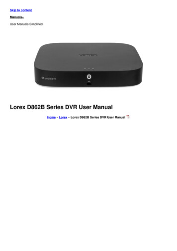
Remote Access with the DDNS ServiceRemote Access with the DDNS ServiceThe L15LD400 Series Observation System can be remotely controlled using your existing networkand the Lorex Client 5.0 software. Recording times may vary - please use the Recording Calculator provided with the CD to find an approximate recording time calculation.1. Connect the Observation System to the Router using the supplied Ethernet Cable. Power theObservation System on.NOTE: The Observation System must be connected to the router prior to powering on thesystem. This allows the system to communicate on your network2. Find the IP address of your Observation System through the Menu System on the unit. To locateyour External IP address, visit http://www.showmyip.com3. Enable PORT FORWARDING on your Router. Refer to the CD, Lorex Website or the RouterManufacturer’s websites for further assistance with your specific network setup and hardware.4. Set up a DDNS web account at http://www.lorexddns.com/5. Setup the Observation System DDNS (based on information setup on the DDNS website in step4).6. Install the Software on your PC. Configure the software to connect using the DDNS.OBSERVATION SYSTEMINTERNETROUTER(Not Included)26PC(Not Included)
Remote Access with the DDNS ServiceIP & MAC Address1. Access the Main Menu Setup screens, andnavigate to the SYSTEM MENU EXTERNAL DEVICE - TCP/IP SETUP - IPSETUP option.2. Record the MAC Address of your system.This information is NECESSARY for theDDNS Setup process. The MAC Addressis 12 characters with no spaces or dashes.3. Confirm that the DHCP MODE is set toAUTOMATIC. This will allow your systemto lease an IP ADDRESS from your router.If the system is not set to AUTOMATIC,change the setting and click IP DETECT the system will obtain an IP address.4. The IP PORT is 50000 by default. The IPAddress, Gateway and Subnet areassigned to your system by your router. Ifthe settings are not displayed, and the unitis set to DHCP MODE: AUTOMATIC, youmay need to click IP DETECT - the systemwill obtain an IP address.5. Press ESC to exit.NOTE: The system will lease networkinginformation from your Router. If you wish toset your information manually, then set theDHCP MODE to MANUAL. Please consultyour Hardware Manual for further Menuoptions.Finding Your External IP AddressYou will need to have your External IP address to confirm the configuration of your DDNSaccount. One of the fastest ways to find this information is to use a 3rd Party website such ashttp://www.showmyip.comYour IP address can also be found within your Router settings. Refer to your router user guide forfurther details.NOTE: Your External IP address may occasionally change, based on your specific InternetProvider. A DDNS Service allows you to connect to your unit, regardless of an IP Address changeby providing you with a Dynamic Address (and connecting via your system specific MAC address).27
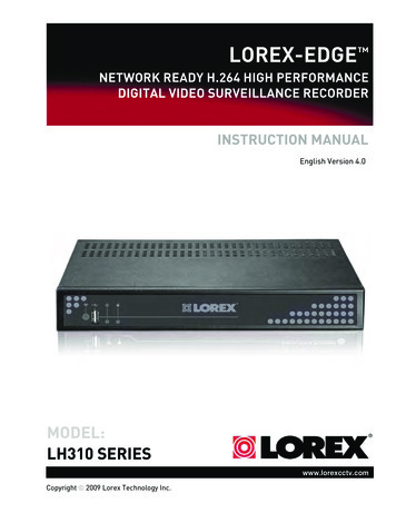
Remote Access with the DDNS ServiceRouter Port ForwardingYou will need to enable port forwarding on your Router to allow for external communications withyour Observation System for port: PORT 50000Computers, Observation Systems, and other devices inside your network can only communicatedirectly with each other within the internal network. Computers and systems outside your networkcannot directly communicate with these devices. When a system on the internal network needsto send or receive information from a system outside the network (i.e. from the Internet), theinformation is sent to the Router.NETWORK EXAMPLERouterExternal IP216.13.154.34RouterInternal IP192.168.0.1ComputerInternal IP192.168.0.2ObservationSystemInternal IP192.168.0.3InternetInternal NetworkWhen a computer on the Internet needs to send data to your internal network, it sends this datato the external IP address of the Router. The Router then needs to decide where this data is tobe sent to. This is where setting up Port Forwarding becomes important.Port Forwarding tells the router which device on the internal network to send the data to. Whenyou set up port forwarding on your Router, it takes the data from the external IP address:portnumber and sends that data to an internal IP address:port number.The instructions found online in the Router Configuration Guide will assist you in the portforwarding configurations for a selection of different router models.Visit our Consumer Guides Support website at http://www.lorexcctv.com for more details28
Remote Access with the DDNS ServiceSetting Up Your DDNS AccountLorex offers a free DDNS service for use with your System. A DDNS account allows you to set upa web site address that points back to your Local Network. The following outlines how to set upyour free DNS account.1. Navigate to http://www.lorexddns.com/2. Select the REGISTER option from the list on the left side of thescreen.3. Complete the NEW USER fields with your personal information: USER NAME - Enter thedesired User Name forconnection. USER PASSWORD /CONFIRM PASSWORD Enter and confirm apasswordfortheconnection.NOTE: The username andpassword provided are NOTthe same as the ADMIN/PASSWORD on theObservation System. Thesecredentials are used for yourspecific connection to yourunit. EMAIL - Enter your EmailAddress.Press the OK button to save the settings.A Successful Registration window will appear.29
Remote Access with the DDNS Service4. Once the account has been created,you will need to login using yourcredentials (as set in step 3).Once the Username and Password havebeen entered, press the LOG IN button toaccess the Configuration Menu.5. Select the ADD DVR link from the top of the page:The DVR Setup screen will appear: DVR NAME - Enter the desi
Lorex Integrated Remote Agent Software Installation Lorex Integrated Remote Agent Software Installation Place the Installation CD in the CD-ROM Drive of your Computer. Select the Install Wizard for the Lorex Client 5.0 Software to begin. 1. Click the NEXT button on all dialogue windows to continue the Installation: 2.