Transcription
ANTENNA BASICSFOR BEGINNERSINTRODUCTIONVERTICALSMULTIBAND VERTICALSDIPOLESMULTIBAND DIPOLESRF CHOKES1
HOW DO ANTENNAS WORK?An Antenna Is A Basic TransducerFor transmitting, you generate an RF signal on a conductor.-Electric fields arise from a voltage rapidly changing-Magnetic fields arise from a current rapidly changingGenerally people don't think of radio-frequency radiation in terms of discreteparticles (oscillating electrons and photons) -they typically use the wavemodel instead, as it's much easier to use.An efficient resonant antenna (1/4 wavelength or longer) produces a largeamplitude EM wave for a given feed power, and produces little heat. Aninefficient antenna produces a small-amplitude EM wave for the same feedpower, and converts most of the power into heat.For receiving, the same resonance issues apply. It's just that whenreceiving, the currents induced on the antenna by the passing EM fieldcause a terminal voltage at the feedpoint of the antenna, which generatesa propagating signal down the coax to the receiver's input amplifier circuit.2
VERTICAL and HORIZONTAL POLARIZATIONThe Electric field or E-plane determinesthe polarization or orientation of the radiowave.For a vertically-polarized antenna, the Eplane usually coincides with the vertical/elevation plane.For a horizontally-polarized antenna, theE-plane usually coincides with thehorizontal/azimuth plane.The Magnetizing field or H-plane lies at aright angle to the E-plane.For a vertically polarized antenna, the Hplane usually coincides with the horizontal/azimuth plane.For a horizontally-polarized antenna,the H-plane usually coincides with thevertical/elevation plane.3
ANTENNA LENGTHλ/2 (180 )λ/4(90 )1 WL (meters) 300 Lambda (λ)F MHzAntenna Length is usuallydescribed as wavelength (WL)in meters or degrees:90 TIME180 Frequency Wavelength(MHz) (Meters) (Feet)1.81605103.7580/75 1.221.225154424.91237.628.5103352618360 360 degdeg Freq Length (ft)ftExample: 50 ft vertical used on 160 m360 degdeg 510 ft50 ft360 X 50 / 510 34.6 degrees4
VERTICALSBasic Vertical (Monopole) Radiation ResistanceRadiation Resistance (Rrad) is thatportion of the antenna input resistancethat radiates power.Radiation Resistance Power radiated / input current squaredFeedpoint Radiation Resistance vs Degrees(Double for Dipole)The other portions are ground loss andantenna structure loss that dissipatepower as heat.Example: 160 m 50 ft vertical 34.6 deg 6 Ohms5
VERTICALSGround Losses (Rgnd) and Current FlowThe further up the element the lesscurrent flows (the voltage increases)Thus, for less I2R ground losses (Rgnd), it’sImportant have more return paths near thefeedpointFeedpointTransceiverNorth Texas soil conductivity is 30 mS/mPoor soil conductivity is 10 mS / meterSea water conductivity is 5000 mS / meterS Siemens (MHOs outdated term)Soil – Ground Rod - Radials6
VERTICALSEfficiency and SWRFeedpoint Resistance (Rin) Rrad Rgnd (RL Rs)Antenna Efficiency RradRinORRradRrad Rgnd (RL Rs)Examples: 50 ft 160 m vertical with 4/8/16 radialsEff 6 Ohms6 20 4 Ohms6 15 4 Ohms6 10 4 OhmsSWR SWR RinCoax Zor 6 Ohms30 Ohms 20% 25 Ohms 24% 20 Ohms 30%Coax ZRrad – Radiation resistanceRgnd – Ground resistanceRL – Loading resistanceRs – Structural resistance(use the larger number on top)Rin50-Ohm Dummy Load 1:150-Ohm CoaxSWR Rin – Feedpoint resistanceat resonance (Xc XL orjX 0)(measured with an MFJ)50-Ohm Coax 2:125 Ohms RinSWR 50-Ohm Coax 1.66:130 Ohms RinSWR 50-Ohm Coax 2.5:120 Ohms7Rin
VERTICALSActual HyGain 18HT Vertical Impedance DataIMPEDANCE ZMFJ 269 ANALYZERResistance RFeedpoint Z R /-jX3.835 MHz 1.22Rs 41 Xs . 550RXL1.220RXc-50RReactance jX3.65 MHz3.80 MHz41 (Rin) – 28 (Rrad) 13 (Rgnd Rs)3.95 MHz28 (Rrad)/ 41 (Rin) 68% Efficiency841
VERTICALSNear Field is the area wherethe ultimate pattern is not fullyformed, and E-H induction fieldshave a noticeable effect onforces we measure.Radiation PatternPseudo-Brewster Angle(PBA): varies with the groundconductivity and dielectricconstant.Frensel Zone is the areawhere the pattern is still beingformed. It may or may notinclude E-H induction fieldareas.Pseudo-Brewster Angle is typically atthe -4 dB point from “perfect” groundAbove this angle, the reflectedsignal is in-phase with thedirect signal and augments it.Simple verticals have theFrensel zone extending outa few wavelengths.Physically large arrays almostalways have large a Frenselzone.Far Field is the area whereany change in distance resultsin no noticeable change inpattern or impedance.The vertically-polarizedreflected wave (from a flatearth or water surface) is 90degrees out of phase andminimum amplitude withrespect to the direct wave.Signal reflection at an in-phase point(Augmentation)Signal reflection at an out-of-phasepoint(Cancellation)Below this angle, the reflectedwave is between 90 to 180degrees out-of -phase with thedirect wave and reduces it.PBA is that angle at which thedirect wave reduces it.-Courtesy of Tom McDermott –N5EG9
DECIBELSThe decibel (dB) is alogarithmic unit that indicates theratio of a physical quantity(usually power) relative to aspecified reference levelThe difference in decibelsbetween two power levels isdefined to be 10 log (P2/P1) dBwhere the log is to base 10Example: 100 W transmitter drivinga yagi antenna with 6 dB gain is equalto a dipole with 400 W drive.10
VERTICALSBasic Vertical (Monopole) Radiation PatternThey say that verticals radiate equally poor in all directionsNot so fast. Maybe soon 20 through 10 metersBut for DXing,160 through 40 metersa vertical can do a goodjob compared to a lowdipole -since it’s moredifficult to get a dipoleup at a good height.Let’s analyze this11
VERTICALS160 m Vertical with two 90 ft radialsComparison between poor ground and good ground3.7 dB(For living inTexas)The unit of antenna gain is dBi. dBi means"Isotropic", a perfect POINT SOURCE,which radiates in a spherical manner. It is arelative measurement12
VERTICALS160 m Vertical with four 90 ft radialsComparison between poor ground and good ground-2.1 to -1.9 dBi(.2 dB)1.6 to 1.8 dBi(.2 dB)13
VERTICALS160 m Vertical with thirty-two radialsComparison between 50 ft and 90 ft radials (Good Ground)-.24 dB(loss for shortRadials)14
VERTICALS50 ft Shortened 160 m Verticals with 32 RadialsComparison between Inductively (coil) baseloaded and centerloaded 2.1 dBCoil electricallylengthens antenna(loads)15
VERTICALS50 ft Shortened 160 m Verticals with 32 RadialsCapacitive (Top Hat) LoadedCapacitive loadingElectrically lengthensantenna16
VERTICALSSummary Between 50 ft Shortened 160 m Verticalsand Full-Size Vertical with 32 radialsRad EffGainLoadingBaseLoaded23.3%-1.5 dBi40.7 WCenterLoaded37.3%0.58 dBi24 WTopLoaded41.8%1.06 dBi---FullSize45.6%1.67 dBi---FS SeaWater95.1%4.92 dBi---17
Comparison between 43 ftand 50 ft matched baseloaded verticals at 3.8 MHz43 ft -coil loss 6.2 W and 8radials is 22.9% efficiencyVERTICALS43 ft VerticalShown with base loadingcoil for 160 m and RF choke50 ft -3.7 W and 16 radialsis 33.9% efficiency 2 dB18
VERTICALSComparison Between Three 10 m Verticals (Mininec Ground)1/4 Wave Vertical¼ Wave Groundplane8 ft Above Ground¾ Wave Vertical-1.1 dBi(.3 dB)4.82 dBi(6.2 dB)-1.4 dBi19
VERTICALS40 m ¼ WL-C Trapped MultibandCapacity Loading (top hat)-Electrically lengthens element20 m Trap20 m ¼ W15 m TrapElectricallySimilarAdd-on trap kitsFixed coil with sliding rodPatent No. 4 496 953 (Butternut)17 m Trap15 m ¼ W10 m ¼ W15 mTrap10 m Trap-An L-C resonantcircuit that acts as aHi-Z point to 10 mAdds inductive loadingto the next bands12 mTrap10 m Trap20
VERTICALSMy 40/20/15/10 m 4-Band 29 ft Homebrew VerticalParallel Elements40 mElement20 m Trap15 mElement10 m Element12 RadialsSeparated for minimumcoupling and interaction21
VERTICALSCCapacity Loading(top hat)¼ W Decoupling Stub MultibandAPatent No. 2 535 298 –W J Lattin (1950)BAVHF/UHF Collinear(J-Pole Match)B40 m LoadingcoilA ¼ wavelength transmission line X velocityfactor is a resonantcircuit which creates aphase shift at which theopen end decouplesthat frequency from themain element10 m20 m ¼ Wwith top hat15 m DecouplingStubCDecouplingStub½WAB½WA different connectionis possible -that is A to C.This results in an insulatoraction or decouplingAB15 m ¼ W10 m ¼ W22
VERTICALSElectricalEquivalentGround Independent Multiband Antennas40 m20 m15 mCapacity HatsVertically PolarizedLoaded Dipole6m10 mRemember Hustler HF Mobile antennas?This is basically what this design is-only mechanically mounted on a mastJust put to two of them back-to-backand use three resonators and thereyou have it-Narrow bandwidth and low efficiencyon 20 and 40 meters2mCenterFedInsulatedtubingBalun/Choke40 mLoading CoilCoaxMast23
VERTICALSTop Fed Antennas -No Radials80 mmodel oftop fedvertical15 ft tobase43 ft VerticalVsTop FedCounterpoiseMatchingNetworkCoax10 mSURPRISE!12 m15m17 mCoax wrappedaround 20 melement to base20 ft20 m40 m30 mChoke80 mDistance AboveGround24
INVERTED-Ls and LONG WIRESSimilar to a Vertical –Have good efficiency due to long length-Require similar matching –a remote tuner can be used37 ft high X 90 ft longFull-size vertical Vs Inv-L comparison40 m Pattern10 m Pattern25
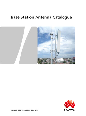
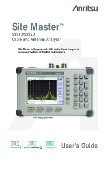
DIPOLES80 m Inv-Vee Apex at 60 ft6.25 dBi1.95 dBiFree Space26
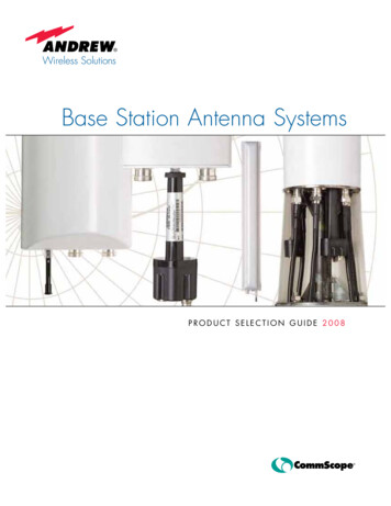
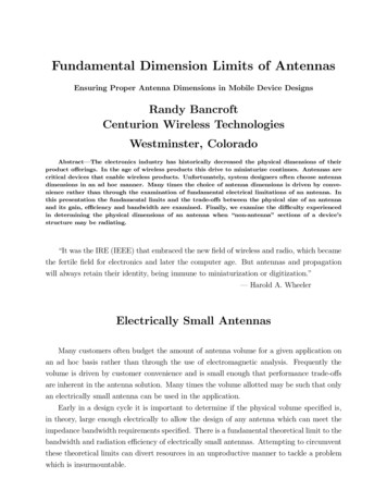
DIPOLES80 m Inv -Vee Height Compared to Full-Sized VerticalDipole HeightIN PH OUT-OF-PHIN PHOUTIN PHOUT-OF-PHFRENSEL ZONENote: For illustration purposes only1 WL High(240 ft Apex)1/4 WL High(60 ft Apex)1/2 WL High(120 ft Apex)27
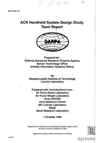
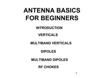
DIPOLES½-Wavelength Dipole Vs Inv-VeeBW 3.72 to 3.874 MHz80 m DipoleZ 76 -j2.5Eff 84.7%Fr 3.8 MHzBW 3.68 to 3.85 MHz80 m Inv-VZ 64 j0.5Eff 76%Fr 3.77 MHz28
LOOPS66 ft X 66 ft X 25 ft High 80 m Horizontal Loop AntennaZ 76 j4Eff 54.9%Fres 3.8 MHzNear Vertical Incidence Skywave (NVIS)29
LOOPSRoof Top 10 m Horizontal Loop Antenna77.5 in. length of75-Ohm coaxto 50-OhmTransformationZ 76 -j2.5Eff 84.7%Fr 28.5 MHzDirect feed75-Ohm coaxSWR curve30
MULTIBANDComparison Between ½ WL Trapped and Open-Wire Center fed Antennas½ WAVEDIPOLE130 ft (7 WL)DIPOLEEach 10 m antenna at 35 ftTrappedCoax feedline(Narrower BW andfewer bands)Center FedOpen feedlineand Tuner31
MULTIBANDParallel (Fan) Multiband AntennaModeling shows extremedifficulty tuning –especiallyon 15 m-I’ve had good luck with twobands (80 and 40 m)With more spacing, modelingshows easier tuning and betterSWR when more bands are addedI think this is a Morgan Trap(H K Morgan 1940 -CQ Mag Feb 1977)Alpha-Delta Fan/Trapped Dipole-Requires calculations todetermine the value of coil XLF1 (20 m) XL Wire F2 (40 m)32
MULTIBAND80 – 10 m W8NX 5-Band Dipole Antenna –My Choice-Coax fed – SWR below 3:1 on all bands-No external tuner required-40 m trap and 20/15/10 m stubs-Full-sized performance 80/40 m-20, 15, and 10 m have multiple lobes33
MULTIBANDOff-Center-Feed and Windom Antennas45’ 4”90’ 8”TUNER-Requires a Tuner-High bands have multiplelobes4:1 balun below 50 ft6:1 balun above 50 ft34
MULTIBANDG5RV Antenna804020 30151210SWR 2.71 4.1 1.9 Hi 5.5 2.6 HiW8JI DesignTuner35
MULTIBANDDecoupling Stub Multiband DipoleLattin Dipole -W4JRW10/20/40 Meter Short Dipole Using 300-Ohm Twinlead40 m20 m10 m8 ft6 ft 11 in13 ft 10 inCoax FeedlineActs as linear loading on 40 mor a ¼ W stub for 20 m80 m addition 27 ft 5 in(if desired)A Future Antenna Project36
RF CHOKESDIFFERENTIAL MODECURRENTWhy Use a Choke?COMMON MODECURRENTXCVR-Isolate antenna from feed line-Reduce noise-Keep RF out of the shackPower (and field) isconfined inside the coaxCommon Mode power(and field) is outside coaxCHOKE20 to 10 m Yagi ChokeBOOMActs like an egg insulatorCHOKEXCVRCoaxSix turns on 4” PVC sewer pipe attached awayfrom the boom to prevent coupling via theboom (12 turns for 40 to 30 m)37
RF CHOKESData from K9YC’s esPPT.pdf38
Ladder LineRF CHOKESWallAntennaTunerElectrical BoxRG-213 CoaxDirect ConnectionThus, making sure that there are nocommon mode currents present isthe key objective, both to minimizenoise pickup and to make sure thatthere are no currents that couldcouple into the house wall. The feedline choke does that very well.Ferrite ChokePVCA resonant antenna will never have a feedimpedance of 400 j0. It will be a lowimpedance near it's resonant, 3rd harmonic,etc. On the even harmonics, it will have a highimpedance. Thus, the 400-Ohm ladder linenever shows an impedance anywhere close to400 Ohms at the transmitter. Thus, a specificimpedance matching ratio is never correct.That's why there's an antenna tuner inside theshack - to match whatever impedance is seento the 50 Ohms that the transmitter wants.-Courtesy of Tom McDermott –N5EG39
THE ENDK5QY40
50-Ohm Dummy Load SWR 50-Ohm Coax 1:1. 8 MFJ 269 ANALYZER IMPEDANCE Z Feedpoint Z R /-jX Resistance R Reactance jX 0R . Free Space 6.25 dBi 1.95 dBi. 27 DIPOLES 80 m Inv -Vee Height Compared to Full-Sized Vertical 1/4