Transcription
LOREX CLIENTRemote Agent SoftwareInstruction ManualEnglish Version 1.0MODEL:SG19LD804-161www.lorexcctv.comCopyright 2006 LOREX Technology Inc.
Table of ContentsTable of ContentsAbout the Lorex Client . 2System Requirements . 3Software Installation . 4-5Lorex Client Software - Main Screen . 6-7Connection Manager . 8Adding a Group . 8Adding a Site (Individual Unit Configuration) . 9-10Configuration Tab . 11Modifying a Site . 12Remote Connection 1 . 13Remote Observation Setup . 14-20Remote Monitoring . 21-23Search Functions . 24-29Web Client . 30Network Setup / Remote Access Overview . 31IP & MAC Address . 32Finding Your External IP Address . 32Setting Up Your DDNS Account . 33-34Router Port Forwarding . 35DDNS SETUP . 36About the Lorex ClientThe Lorex Client software package allows you to access your Observation System from a remotelocation to view live and previously recorded video. View and Record from your PC - Connect your Observation System to your Network Minimum System Requirements: Windows XP, Pentium 4 processor with 256MB RAM (512MBRAM recommended)Please visit us on the web for the most current Manuals, Quick StartGuides and Firmware. Additional Language Manuals are also available at:http://www.lorexcctv.com2
System RequirementsSystem RequirementsThe Lorex Client software (included with the Observation System) has the following installationrequirements.Minimum System Requirements:Operating SystemWindows 2000Windows XP Home EditionWindows XP ProfessionalProcessor.Pentium 4 - 1.5 GHz Processor (or equivalent)Memory256 MB RAM (512 Recommended)Hard Drive50 MB - Installation space required* Additional Hard Drive space required for recording.Recorded file size will vary depending on recordingquality settingsRecommended System Requirements:Operating SystemWindows XP Home EditionWindows XP ProfessionalProcessorPentium 4 / 3 GHz Processor (or equivalent)Memory1024 MB RAMHard Drive50 MB - Installation space required* Additional Hard Drive space required for recording.Recorded file size will vary depending on recordingquality settingsPlease refer to the Lorex Client Software User Guide included with your Observation System forfurther details.Visit the Lorex support website at http://www.lorexcctv.com for information on Windows Vistacompatibility.3
Software InstallationSoftware InstallationPlace the Lorex Client Installation CD in the CD-ROM Drive of your Computer. The SoftwareInstall Wizard for the Lorex Client Software will begin.1. Click the NEXT button on both dialogue windows to continue the Installation:NOTE: If the Installation Process does not automatically start, you will have to begin theinstallation process manually: Double Click the MY COMPUTER icon on your Desktop Double Click the CD-ROM DRIVE (Drive Letter will vary depending on the number of drivesin your computer) Double Click the SETUP.EXE file (may appear as SETUP with no file extension,depending on your system settings.The Installation Process will begin.4
Software InstallationSoftware InstallationPlace the Lorex Client Installation CD in the CD-ROM Drive of your Computer. The SoftwareInstall Wizard for the Lorex Client Software will begin.1. Click the NEXT button on both dialogue windows to continue the Installation:NOTE: The following Program Shortcuts will be created: Start Menu - Programs - Lorex ClientzLorex ClientzLorex Player Desktop Shortcuts for:zLorex ClientzLorex PlayerInstalling the CodecsTo playback the recorded AVI files, the Video Codecneeds to be installed:1. Run the CODEC.EXE file located on the Software CD2. Accept the default propts during the installation, andclick the Finish to complete.5
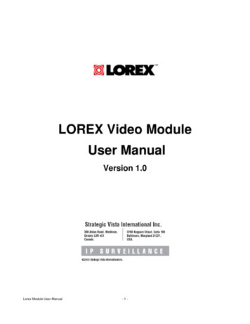
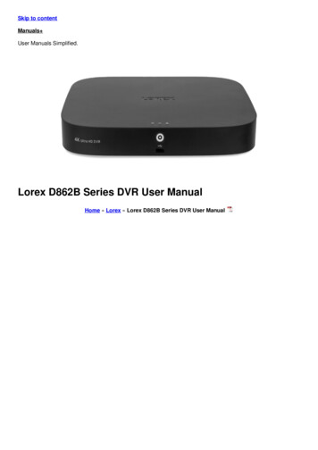
Lorex Client Software - Main ScreenLorex Client Software - Main Screen41567891011122133141. Main Screen - Displays live Camera images (delays in images are due to Network speed andconnectivity strength).2. Connection Status - Displays the Observation System connection status.3. Camera Selection Buttons - Displays the Connected Camera Number. Press buttons 1 8 toselect a Camera Number for display.4. Minimize / Exit Minimizes the Client Window Exit Program.5. Time Display - Shows the current Time & Date.6. Search / Setup Buttons Search Mode - Search for previously recorded video. Connection Manager - Configurations for Network Connection and Local Recording. Remote Observation System - Changes the setup on the remote Observation System.6
Lorex Client Software - Main Screen41567891011122133147. DVR Selection - Select the Connection ID for the Observation System.8. Connect / Disconnect Buttons Connect: Connect to the Observation System. Disconnect: Disconnects from the Observation System.9. Screen Display - Changes the Screen View (Single, Quad, 9, Full screen or Tiled).10. Save to File - Saves the currently displayed video to an AVI file on the local PC.11. Event viewer - Displays the Event List and Image Search functions.12. PTZ Control Button - Controls Cameras with PTZ & Focus configured (refer to the InstructionManual for the Observation System).13. Alarm and Audio Buttons Mic. Speaker Volume Alarm On/Off.14. Exit - Closes the Lorex Client software.7
Connection ManagerConnection ManagerThe Connection Manager contains the setup information to allow the user to remotelyconnect to the Observation System.Adding a GroupGroup - Right click on‘Site’ to add a New Group.A group can representone or more ObservationSystems.For Example, you mayhave more than onesystem in your office, sowould name your group‘OFFICE’.Each individual unit canthenbeconfiguredseparately for connection.Enter a name for theGroup.8
Connection ManagerAdding a Site (Individual Unit Configuration)DVR Information - Enterthe information specific tothe unit (refer to page 30for setup instructions): Name - Enter a name forthe unit. IP / Domain Name Enter the IP address orDomain Name for theSystem. This will varydependingonsetup(InternalNetworkConnection or ExternalRemote access throughthe Internet)- refer to page30 for setup details. Port - Set to 6100 bydefault. User ID - Enter the USERID to connect to the system(the USER ID is configuredon the System - i.e. ADMIN- case sensitive). Password - Thepassword used to accessthe System (i.e. TheADMIN password is set to1234 by default).Camera Assign - Seteach camera to a portionof the 9-view window byusing the drop downmenu selections.ADD Button - Adds thesite to the Group.OK Button - Accepts thechanges and Closes theconfiguration Window9
Connection ManagerConfiguration TabVideo OSD - Sets thedisplay options for theVideo: Title Name - Displays thename of the Camera Date - Displays the date Time - Displays the time Resolution - Displaysthe video resolutionVideo Output - Sets theVideo Output type toOverlay Mixer, VideoReceiver or GDI.Video Mode - Sets theVideo Mode: ScreenSwitchingInterval - Sets the screenswitchingtimeforSequence view. Alarm Popup - Sets theDisplay popup when anAlarm is detected on thesystem Quality Improve Adjusts the Video qualitySave Directory - Browseto set the default savelocation for Video images.10
Connection ManagerModifying a SiteLeft click on the selectedSite (from the GroupListing) to access thesettings.DVR Information - Canbe changed if desired.Camera Assignments Camera default positionscan be reassigned ifdesired.Event Selection - Selectsthe types of Events: System Alarm Video RecordFor detailed informationon Events, refer to theSystem InstructionManual.IN/OUT Selection - Setsthe Audio and Alarm out. Audio Out - Sends Audioto the System Alarm Out - Sends Alarmto the System Monitoring Audio - Setsthe default channel forAudio Monitoring. Connection Count Maximum connections.MODIFY Button - Saveschanges to the Siteconfiguration.DELETEButtonDeletes the site from theGroup ListingOK Button - Accepts thechanges and Closes theconfiguration Window11
Remote ConnectionRemote ConnectionOnce the site setup profile has been created, a connection can then be made to the ObservationSystem:1. Select the Site profilefrom the Dropdown List.2. Press the CONNECTbutton.The Connection Statuswindow displays the stateof the connection.Onceasuccessfulconnection to the Systemhas been made, the blackscreen view will switch toLive Camera View mode.NOTE: If another user isconnected to the Systemusingthesamecredentials (i.e ADMIN),the connection will berejected.12
Remote Observation SetupRemote Observation SetupThe Remote Observation Setup allows the user to make changes to the remote system.Entering the System PasswordChecking Authority - TochangetheRemoteSystem Settings, the useris required to re-enter theADMIN password, andpress OK.Recording Setup - Simple Record Mode - Select the RecordingSetup type (Simple or Advancedconfiguration). Camera Group - Select Cameras1 4 or 5 8 for setup. Record Quality - Sets the RecordingQuality. Select HIGHEST, HIGH,STANDARD or LOW. Record Size - Sets the RecordingSize (video display). Select352x240, 704x240 or 704x480. Record Frame Number - Sets theRecording Frame Rate. Select 1, 2,3, 7 or 15 FPS Use the Mouse to select or deselectSchedule options (Blue Highlightedblocks indicate that the segment isSelected).13
Remote Observation SetupRecording Setup - AdvancedSelect the Advanced option from theRecord Mode dropdown menu. Anwindow will appear to indicate that theMode has changed. Camera Group - Select the ChannelArea (CH1 4 or CH5 8) Schedule Mode - Set to Weekly orDaily. When the System is set toweekly mode, set each dayindividually Pre Event Recording Time - Setsthe Pre-Event Recording Time(between 0 5 Seconds). ThePre-Event records the data thatoccurred before the Event occurred.Refer to the Observation SystemInstruction Manual for more details. Post Event Recording Time - Setsthe Post-Event Recording Time(between 5 180 Seconds). ThePost-Event records the data thatoccurred after the Event occurred.Refer to the Observation SystemInstruction Manual for more details Alarm / Continuous / MotionRecord Setup - Click the “Set”Button to setup the Cameras forAlarm, Continuous and MotionRecording: Set the Size, RecordingRate. Quality and Audio for eachcamera. Press OK to save theSettings. Alarm / Continuous / MotionRecording Schedule - Use themouse to select individual timeblocks for Alarm, Continuous andMotion Recording. Selected blocksare displayed in Blue.14
Remote Observation SetupCamera SetupSettings for Individual Camera recording Camera Group - Select Cameras1 4 or 5 8 for setup. Covert / Title - Sets the Covert statusand Name for each camera. RefertotheObservationSystemInstruction Manual for more detailson the Covert Camera Setting. Color Setup - Sets the Brightness,Contrast, Tint and Color for eachcamera. PTZ Setup - Set the Address, PTZProtocol and Baud rate for eachcamera. Click the Properties buttontoenteradditionalsetupinformation. Refer to the specificPTZ Camera Manual for details onconfiguration. Motion Area - Click the “Camera”Button to access the Motion SetupMenu. Select an area by click anddragging with the mouse. TheSelection menu will automaticallyappear to Select/Deselect/Cancelthe Motion Setup.15
Remote Observation SetupSound Setup Live Audio - Sets Live Audio to ON/OFF. Audio monitoring channel - Setsthe channel for Live AudioMonitoring (1 4 Only). Network Audio TX - Sets theNetwork Audio transmission to ON/OFF. Network Audio RX - Sets theNetwork Audio Receive to ON/OFF. Buzzer Setup - Turns the alarmbuzzer OFF when a button ispressed on the System Front PanelKeypad.16
Remote Observation SetupEvent/Sensor Setup Alarm Input - Sets the Alarm InputOperation to Enabled or Disabled,and sets the Type to Normally Openor Normally Closed. Refer to theObservation System Manual fordetails on configuration of ExternalAlarm devices. HDD Event - Turns the Alarm On/Offwhen a problem is detected with theSystem Hard Drive. Alarm Out - Sets the Alarm out fora secondary Alarm Device. Refer tothe Observation System Manual fordetails on configuration of ExternalAlarm devices. Operation: Set the RelayConnect with Alarm Sensor toON/OFF. Mode: Set the Reacted Relay toLatched or Transparent Mode. Type: Set to Low (NormallyClosed) or High (NormallyOpen) Duration: Setup Reacted RelayTime. (5sec 5min or Untilkey-in) Buzzer Out - Sets the audible buzzeralert when an event is detected. Buzzer: On/Off Duration: Sets the Buzzer time(5sec 5min or Until key-in). Mode: Setup Reacted Relay asLatched/Transparent Mode. HDD Event: Alarm On/Off whenHDD has the problem. E-mail Notification - Generates anemail notification when an Event isdetected. Refer to the ObservationSystem Manual for details onconfiguration of Email Notification.17
Remote Observation SetupSystem Setup System Info - Displays the SystemInformation including the Softwareand Hardware versions, VideoSignal type, IP and MAC addresses,and Disk Space usage. SMTP - Setup the mail server anduser’s E-mail (for email send onEvent notification): Server: The Internet Provider forEmail Sending Port: Default port 25 User: Enter the User ID used bythe Internet Provider forInternet connectivity. Password: Enter the Passwordused by the Internet Providerfor Internet connectivity. Security: Set the security. Users - Setup/Modify System Usersby pressing the “Add” or “Modify”buttons. Network Speed - Set the networkconnection speed. Disk Overwrite - Sets theObservationSystemHDDOverwrite On/Off. Record Time Limit - Select the time(Off, 12 hours, 1day, 2day, 3day,1weeks or 1month)18
Remote Observation SetupDisplay Setup (Screensaver) Auto Brightness - select the time(10 min., 20min, 30min, 40min,50min or 1 hour). If a time is set, theRemote System screen will go darkafter the set time interval. Main Display Off - Turns the mainSystem screen On/Off duringspecified times: From: Main Display Off start time To: Main Display Off end time. * If selecting the “Off”, “maindisplay off function” does notwork.19
Remote MonitoringRemote MonitoringOnce the site setup profile has been created, a connection can then be made to the ObservationSystem:1. Select the Site profilefrom the Dropdown List.2. Press the CONNECTbutton.Screen View ControlsSingle Camera View16 Camera ViewQuad View8 Camera ViewSequence ModeFull Screen ViewManual Switch Mode20
Remote MonitoringPTZ ControlsPress the PTZ Button to access the extended PTZ Menu:P/T/Z Controller - Movethe Camera Pan/Tilt usingthe Direction KeysFOCUS/ZOOM SelectButton - Controls theFocus or Zoom Controlusing the and - ButtonsAVI File Conversion Press the AVI (Video)Save Button to startVideo Recording to the local PC A dialogue box will appear whilevideo is saving. Press STOP to endthe video. A second dialogue box will appear,indicating the saved files. The filesare saved in the default locationspecified in the System Setup.21
Remote MonitoringEvent Viewer No - Event order number DVR - Indicates the ObservationSystem name where the eventoriginated. CH - Indicates the channel where theevent occurred (if applicable) Time - Displays the Time and Datethat the event occurred at. Description - A description of theevent type.22
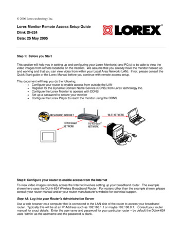
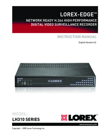
Search FunctionsSearch FunctionsThe Remote Observation Setup allows the user to search for video and events.134567281. Search Screen - Displays the Selected Video.2. Search Bar - Search & Display Camera Recording Times (24 hours).3. LIVE Button - Return to Live Viewing ModeSETUP Button - Access system settings.4. Screen Layout - Change the display screen view.5. SEARCH - Backup Video or Search for Events.6. Camera Selection Button - Select individual cameras.7. Quick Search - Find information by Date & Time.8. Search Controller - Video playback controls23
Search FunctionsEvent ViewerIndicates0 24 hourTimeIndicates Recording Status:Grey (No Recording) andWhite (Recorded Data).Search Bar - Drag toselect the recording time.Displays theCamera recordingchannelVolumeControlChannel Bar - Scroll toselect different cameras.Search By TimeSelect date and TimeVideo PlaybackControls: Play video innormal speed (Playand ReversePlayback)24Change PlaybackSpeed (up to 64xForward and Reverse)
Search FunctionsSearch OptionsArchiveCopies a backup of the video data from the Observation System to the local PC. Time Range - Set the start and endtimes for backup. Channel - Select channels toBackup. Include Audio - Includes Audio withthe video backup.Press OK to start the backup. A statuswindow will appear for the backupprocess.Once complete, the window willdisappear and the data will be saved inthe designated folder.25
Search FunctionsBackup PlayPlays back previously saved video data:Video Playback Image(only one camera can bedisplayed at a time)Select the Date and Timefor the video playbackPlayback Controls (Seeprevious Search optionsfor details).Displays the currentlydisplayed file name.Image Save Function Click the ‘Save Image’ Icon duringVideo Playback. Enter a file name, select a File Type(JPG or BMP), and Location. Pressthe SAVE Button. The current image will be saved.26Total playback time forthe video recording.
Search FunctionsPrint Function Prints the currently displayed image.Select the Printer, and press OK.Log ViewerSearch Range Set the Start Dateand TIme, andEnd Date andTime.Search Button Press to perform asearch based onCriteriaSearchCondition Select the Searchcriteria (Alarm,Motion,Continuous orSystem).Logs Displays logs(based on SearchRange andSearchConditions).Displays the LogNumber, Channel,Date andOK ButtonMove to Previous or Next Page, oruse the dropdown to select aspecific page number.Return to Timeline View(Search Mode).27
Search FunctionsEvent ViewerDisplays a list of all Events. NO - Event Number DVR - Displays theObservation System wherethe event originated from. CH - Displays the channelnumber where the eventoccurred (if applicable.Some event types will not bedisplay a Channel number) Date and Time - The dateand time that the eventoccurred Description - Displays adescription of the Eventtype.28
Web ClientWeb ClientOnce the System is configured, a connection can be made using Internet Explorer (onlysupported Web Browser). Enter the IP Address or DDNS Address of the Observation System in the Address Bar ofInternet Explorer. A prompt will appear for Active-X - choose to install the controls. The Lorex Client software will install remotely, and have the same functionality as the fullinstallation (from CD).29
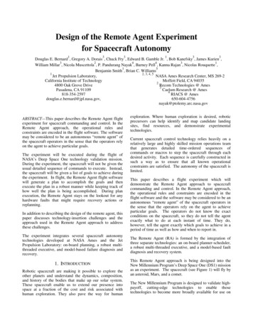
Network Setup / Remote Access OverviewNetwork Setup / Remote Access OverviewThe SG19LD804-161 Observation System can be remotely controlled using your existing networkand the Lorex Client software.1. Connect the Observation System to the Router using the supplied Ethernet Cable. Power theObservation System on.NOTE: The Observation System must be connected to the router prior to powering on thesystem. This allows the system to communicate on your network2. Find the IP address of your Observation System through the Menu System on the unit.3. Set up a web account at http://DDNS.strategicvista.net.4. Enable PORT FORWARDING on your Router. Refer to the included Router Guide and Basicsof Remote Video Access Guide for further assistance with your specific network setup andhardware.5. Setup the Observation System DDNS (based on information setup on the DDNS website in step3).6. Install the Software on your PC. Configure the software as outlined on page 8 of this manual,using the information gathered on the following pages.OBSERVATION SYSTEMINTERNETROUTER(Not Included)30PC(Not Included)
Network Setup / Remote Access OverviewIP & MAC AddressThe IP & MAC Addresses arenecessary for DDNS Setup (for remoteaccess to the Observation System).To Locate the System information,Press the ENTER button on the FrontPanel or Remote Control while viewingthe Cameras. The System Info windowwill be displayed.IP AddressMAC Address- OR 1. Press the Menu Button on the FrontPanel or Remote Control to access theSetup Menu. Select the System Setupoption and press the Enter button.2. Navigate to the System Menu option.Press the Enter button to access theSystem Menu.3. Navigate to the System Managementmenu, and press the Enter Button toaccess the settings.4. Select the System Information option,and press the Enter Button to displaythe System Settings.IP AddressMAC AddressFinding Your External IP AddressYou will need to have your External IP address to set up your DDNS account. One of the fastestways to find this information is to use a 3rd Party website such as http://www.showmyip.comYour IP address can also be found within your Router settings. Refer to your router user guide forfurther details.31
Network Setup / Remote Access OverviewSetting Up Your DDNS AccountLorex offers a free DDNS service for use with your System. A DDNS account allows you to set upa web site address that points back to your Local Network. The following outlines how to set upyour free DNS account.1. Navigate to http://DDNS.strategicvista.net2. Select the Create Account option from the list on the left sideof the screen.3. Complete the Account Information fields with your personal information4. Complete the System Information fields: Product License: Select your product model from theProduct License drop down menu Product Code - MAC Address : Locate the MACaddress of your (recorded while loading the System) URL Request: Choose a URL for your DDNS connection(i.e. your name, your company or business name, oranything of your choice.)32
Network Setup / Remote Access Overview1. Click the Create New Account link at the bottom of the form to submit your request.2. Your Account information will be sent to you at the E-mail Address you used in Step 3.Service provider:User Name:Domain mith(your password)You will need this information for remote access to your System. Record YOUR informationbelow:User Name:*Domain Name:Password:* Only the first part of the Domain Name is required for setup on theSG19LD804-161 System. If the full Domain sent is tomsmith.strategicvista.net, the unit only requires that only tomsmith be entered.33
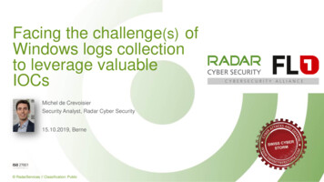
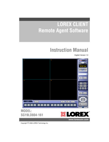
Network Setup / Remote Access OverviewRouter Port ForwardingYou will need to enable port forwarding on your Router to allow for external communications withyour Observation System for ports: TCP/IP PORT 6100 WEB PORT 80Computers, Observation Systems, and other devices inside your network can only communicatedirectly with each other within the internal network. Computers and systems outside your networkcannot directly communicate with these devices. When a system on the internal network needsto send or receive information from a system outside the network (i.e. from the Internet), theinformation is sent to the Router.NETWORK EXAMPLERouterExternal IP216.13.154.34RouterInternal IP192.168.0.1ComputerInternal IP192.168.0.2ObservationSystemInternal IP192.168.0.3InternetInternal NetworkWhen a computer on the Internet needs to send data to your internal network, it sends this datato the external IP address of the Router. The Router then needs to decide where this data is tobe sent to. This is where setting up Port Forwarding becomes important.Port Forwarding tells the router which device on the internal network to send the data to. Whenyou set up port forwarding on your Router, it takes the data from the external IP address:portnumber and sends that data to an internal IP address:port number (i.e Router External IP216.13.154.34:6100 to Observation System Internal IP 192.168.0.3:6100).The instructions found online in the Router Configuration Guide will assist you in the portforwarding configurations for a selection of different router models.Visit our Consumer Guides Support website at http://www.lorexcctv.com for more details34
Network Setup / Remote Access OverviewDDNS SETUPOnce the DDNS settings have beenconfigured online, the information must beentered on the Observation System to allowfor remote connection via the Lorex ClientSoftware (or through Internet Explorer):1. Access the Main Menu Setup screens, andnavigate to the SYSTEM option. Press theENTER button to access the setup.2. Navigate to the NETWORK option. Pressthe Enter button to access the Networksettings. Select the DDNS Server option,and press the ENTER button to enter theDDNS SETUP.3. Enter the information received in email(including the password). Press the DDNSStatus first - wait for the SUCCESSMESSAGE (as long as the information iscorrect).Select OK to save the settings.NOTE: Once all Network settings are configured, the System can be accessed usingthe Lorex Client Software. Refer to Page 8 for Connection Manager details.35
It’s all on the webProduct InformationSpecification SheetsUser ManualsSoftware UpgradesQuick Start GuidesFirmware X Technology Inc.
Software Installation Place the Lorex Client Installation CD in the CD-ROM Drive of your Computer. The Software Install Wizard for the Lorex Client Software will begin. 1. Click the NEXT button on both dialogue windows to continue the Installation: NOTE: If the Installation Process does not automatically start, you will have to begin the