Transcription
LOREX Video ModuleUser ManualVersion 1.0Lorex Module User Manual-1-
Table of Contents1. Introduction . 31.1 Features . 31.2 The Lorex module as a Web-based Remote Surveillance System . 41.3 Package Contents . 42. Install Lorex module, USB Camera and Network . 62.1 Installation Procedure. 63. Installation and Configuration . 83.1 Installing the Lorex Utility . 83.2 Using the Lorex Utility . 93.3 Using the Setup Wizard. 103.4 Launching the Lorex Module Browser. 123.5 IP Configuration. 123.6 Upgrading the Lorex Module Firmware . 133.7 Installing the Lorex ActiveX control . 133.8 Installing Java. 134. Lorex Web-based Viewer. 144.1 Viewing Live Images . 144.2 Module Information. 154.3 Basic Settings. 164.4 Advanced Settings . 18Lorex Module User Manual-2-
1. Introduction1.1 FeaturesThe Lorex Video module is a compact stand-alone web-server capable of remote video surveillance. Itcan be accessed from anywhere in the world via a standard browser by entering the IP, account andpassword. Each system can simultaneously support any two combinations of USB PC cameras(regular, infrared or pan-tilt).With its built-in web-server, the Lorex module can stream video images directly to the Internet withouthave to go through a computer. The Lorex module software allows the computer user to monitormultiple cameras on one screen and to archive streaming video directly to the hard-drive.Features: Built-in Web Server 10/100Mbps Fast Ethernet Network Access LCD display shows the IP address, Subnet Mask and Gateway 32-Bit RISC CPU 1MB Flash Memory 8MB Dynamic Memory Support Up to 30 Remote Viewers for each camera Allow Up to 8 User Accounts and Passwords 5.3VDC 1A Maximum Operating Temperature: 0 C 60 C Operating Humidity: 10% 90% Dimensions: 48mm x 63mm x 21m Weight: 75g For Indoor Use. Protective housing required for use Network Protocols: HTTP, TCP/IP, UDP, SMTP, Dynamic DNS, DNS Client, SNTP, BOOTP,DHCP, FTP, SNMP Supports all USB PC Cameras with VIMICRO ZC0301 Plus processor Resolution: 640 x 480, 320 x 240, 160 x 120. Frame Rate: Up to 20fps in 320 x 240 MJPEG Compression 2 USB Ports for PC Cameras USB 1.1 & 2.0 compliant Can be used with two different PC cameras Supports Pan/Tilt and Infrared USB PC CamerasLorex Module User Manual-3-
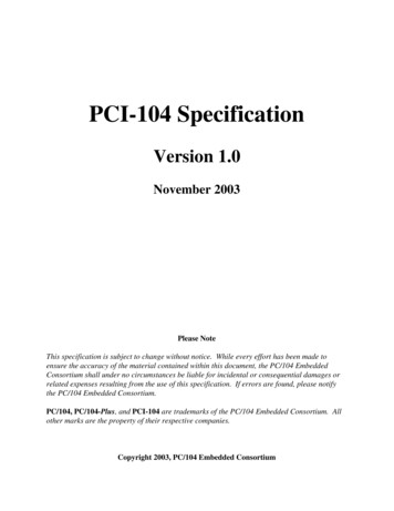
1.2 The Lorex module as a Web-based Remote Surveillance SystemOnce the Lorex module is installed, the user can check any of the connected PC cameras using astandard web browser. The user can monitor and control these cameras by entering the IP address ofthe Lorex module (as set up with Lorex Utility) from anywhere in the world as long as there is anInternet connection available.The Lorex module Network Diagram1.3 Package ContentsYour Lorex module package should contain the following items;1. Lorex module,2. Lorex USB camera,3. Lorex module CD, which contains; Lorex Utility: to configure IP address, update the firmware, etc. Lorex Player: Windows video monitoring and recording application. Adobe Acrobat 5.0 Reader. Lorex user manuals, and Web-support components4. 5.3V DC Adapter5. CAT5 Network cableLorex Module User Manual-4-
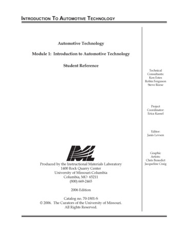
The Lorex module Front ViewThe Lorex module Back ViewLED Status Indicators on the Lorex moduleLight colorSignal definitionCondition descriptionGreenPower stateOn: Normal powerRedError ConditionOn: Error condition occurredOn: When a user is logged in andOrangeLogon statereceiving image data.Flashing: Receiving data viaYellowUSB data activityUSB.Light indicators on the Lorex module LAN Port LEDLight colorCondition descriptionOn: Internet speed is 100Mbits/sGreenFlashing: Data transmitting/receivingOn: Internet speed is 10Mbits/sYellowFlashing: Data transmitting/receivingLorex Module User Manual-5-
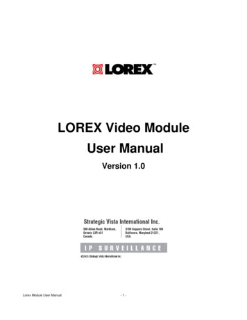
2. Install Lorex module, USB Camera and NetworkThe following details the installation procedure for the Lorex module.2.1 Installation ProcedureStep 1:Plug the PC camera intothe USB port of theLorex module.Step 2:Connect the Lorexmodule to LAN by usingthe Ethernet networkport.Step 3:Plug the DC poweradapter output into theLorex module socket,and plug the DC powersupply into the wallsocketLorex Module User Manual-6-
Step 4:The LCD will display the IP,Subnet Mask and Gateway IP.The icon on the LCD showsthat a USB camera isconnected.The LCD display shows thattwo USB cameras areattached to the Lorexmodule.Lorex Module User Manual-7-
3. Installation and Configuration3.1 Installing the Lorex UtilityInsert the Lorex CD into the CD-ROM drive. The Lorex setup will run automatically. The followingmenu will be displayed.¾ Lorex Utility - This is a program that helps the user configure the hardware. It will detectthe current configuration and take the user through the necessary network setup.¾ Lorex Player - This is a Windows based program designed to allow the user to view andrecord video from multiple Lorex modules.¾ User Manuals - Click to read the Lorex User Manuals. You will need to have AdobeAcrobat Reader v5.0 or higher installed.¾ Acrobat Reader - This will install Adobe Acrobat Reader v5.0 on your local hard drive.¾ Other - Install Java (J2SE 1.4) and Lorex ActiveX components for viewing video from aWeb browser.Click on Lorex Utility button and follow the on-screen instructions to install the utility program.Lorex Module User Manual-8-
3.2 Using the Lorex UtilityWhen you start up the Lorex Utility, it will search and list all available network cards on your system. Ifmore than one is installed, select the network adaptor that you are currently using and click “OK”.The Lorex Utility Network Adaptor Selection on Start-upThe Lorex Utility main menu is shown below. The selection menu is located on the left. The SerialNumber, current Firmware and IP Address of every Lorex module connected to the LAN will bedisplayed on the table to the right.The Lorex Utility Main MenuLorex Module User Manual-9-
3.3 Using the Setup WizardUse “Setup Wizard” to take you through the basic configuration necessary to start using the Lorexmodule.Click to highlight the Lorex module on the right that you want to configure.Click on “Setup Wizard”.The Setup Wizard will launch to take you through the configuration below;Camera SetupChoose the appropriate frequency (Indoor 60 Hz,Indoor 50 Hz or Outdoor) to prevent flickering onthe video feed.Enter a name for the camera in the “Location” boxto identify it.Click on “Next ”Network SetupChoose “Obtain an IP address by DHCP” ifa) you are not sure what the networkaddress should be andb) your network supports DHCPotherwise choose “Use the following IP Address”and enter an appropriate internal IP Address,Subnet Mask and Gateway for the Lorex module.Click on “Next ”Lorex Module User Manual- 10 -
Dynamic DNS SetupYou will need to set up this feature only if you areusing a Dynamic IP address (go tohttp://ddns.stratgicvista.net for details).Click on “Next ”Administrator Account SetupAn administrator account is necessary to ensureprivacy. If you do not set one, the Lorex modulecan be viewed by anyone on the web.NOTE: Make a note of the administrator nameand password and save it in a safe place.Click on “Next ”Upload and Save ChangesClick on “Next ” to save and restart the Lorexmodule with the new configuration.Lorex Module User Manual- 11 -
3.4 Launching the Lorex Module BrowserOnce you have finished with the above Setup Wizard, either click “Launch Viewer” or double click onthe Lorex module item in the list to launch the web browser.3.5 IP ConfigurationThis section allows you to change the IP address of the Lorex module.Select the Lorex module on the right display screen, and then click “IP Configuration”. This will bringup the IP Address Configuration window. There are two tabs; IP Address Advanced (for port setting configuration)IP AddressUse this section to set the IP Address of the Lorex module.Once the IP Address is set, you will be able to connect to the Lorex module by entering this IPAddress into a browser.AdvancedThis section sets a security password for access to devices through the Lorex Utility.Device Password: Use this to set an access password. Once set, the user must enter the password toaccess the device. In addition, the IP Address will not be shown on the right display panel of the LorexUtility.The Lorex Utility will request the “Input Device Password” when you click either “Setup Wizard”,“Launch the Lorex module” or “IP Configuration”WARNING: Do not lose this password. If the password is lost, you cannot access the device to makechanges.To remove the password, you must first enter a valid “Input Device Password”, go to “DevicePassword” and delete the entries, click “OK”.Management Protocol: The administrator can determine the port setting when providing access viaHTTP (web) to the Lorex module. The default port number is 80. Uncheck to disable this function.Lorex Module User Manual- 12 -
3.6 Upgrading the Lorex Module FirmwareThe Lorex Utility offers a convenient method to upgrade the Lorex module firmware.1. Click “Upgrade Firmware” to bring up the Wizard.If you have downloaded the latest firmware to your local hard drive, check “Upgrade the Lorexmodule firmware with file saved on the local hard drive” and browse to the file location.2. Click on “Next ” to check for the latest available firmware.3. Select new firmware file (*.bin)4. Click on “Start”.The Lorex module red and yellow LED will flash alternately to indicate that firmware upgrading is inprogress. Once completed, the Lorex module will reboot.NOTE:If the downloading / upgrade process is interrupted or the data is corrupted, the Lorex module willkeep its default firmware to avoid complete data loss. If this happens, repeat the above firmwareupgrade procedure.Please check http://www.lorexcctv.com/ for the latest firmware.3.7 Installing the Lorex ActiveX controlThe Lorex ActiveX control is required to view video images using Microsoft’s Internet Explorer webbrowser.From the Install CD, click on ‘Other’ and select “Install ActiveX control” from the menu and follow theon-screen instructions.3.8 Installing JavaJava is required to view video images from a web browser other than Microsoft’s Internet Explorer.From the Install CD, click on ‘Other’ and select “Install Java” from the menu and follow the on-screeninstructions.Lorex Module User Manual- 13 -
4. Lorex Web-based ViewerAfter you have set up the hardware and set an IP address for the Lorex module, you will then be ableto go to the Lorex module web site to monitor and control the PC cameras. All you have to do is enterthe Lorex module’s new IP address into the web browser.Once you have done the above, the Lorex module login screen will appear. Key in the administratoraccount name and password entered earlier (if you did not input one, then just press ENTER or clickon the “OK” button). The Lorex module web page will appear.4.1 Viewing Live ImagesIn order to view live images with the Lorex ActiveX control you must use Microsoft’s Internet Explorer6.0 or higher. You may need to pre-load the control (see Lorex Utility) to allow this to work.Alternatively, you can use Sun’s Java with your choice of browser, provided this has been installed onyour computer.Click 'ActiveX' or 'Sun Java' for Camera A or Camera B to view the video images.Note: The first USB camera connected to the Lorex module will be denote as “Camera A”, and thesecond camera connected will be “Camera B”. If there is only one camera, it will always be “CameraA”.Make sure to adjust the USB camera lensfor best picture results.Click on the controls along the Window tocontrol the camera.Functions are: Record the current image to thelocal hard driveDigital zoom in, digital zoom outRotate left, rotate rightFlip image verticallyFlip image horizontallyAuto-panPan left 5 deg/1 degPan right 1 deg/5 degTilt up 5 deg/1 degTilt down 1 deg/5 degNote that the pan and tilt controls will onlywork with cameras that have this functionbuilt in.Lorex Module User Manual- 14 -
4.2 Module InformationClick on the ‘Information’ link in the left hand navigation pane to expand the list of options. Select oneof the options under ‘Information’System StatusThis provides a summary of the module andnetwork status.Take note of the unique MAC address, which isneeded to register for product software,services and support.Current ConnectionsThis section will show all the users currentlyviewing either Camera A or Camera B. It alsolists the login time and total bytes received.A total of 10 connections can be displayed atthe same time.The administrator has an option to block the IPor disable the account of any viewer.Event LogThis section will keep a record of all events thatoccurred in the Lorex module. The user canRefresh, Clear or Save the log file. There is alsoan option to sort the logs according to “Level” or“Type”.The Lorex module can log up to 2,000 events.Note: Set the internal clock to ensure that thelogs are correctly time-stamped.Lorex Module User Manual- 15 -
4.3 Basic SettingsCamera SettingsBy default the Camera Settings page isdisplayed when you log in.Anti Flicker: Choose between 50Hz, 60Hz orOutdoors. Note: If you do not choose the rightfrequency, the image will flicker or lines willappear on the images.Maximum Number of Connections (1-30): Limitthe number of users that can connect to thiscamera.Location: Enter a location/name for the camera.Exposure (1-100): Set this to “Auto”, or click“Manual” to fix the exposure.Light Compensation: Choose “Yes” and theLorex module will increase the lighting of theimage. This is useful when monitoring indoors.Choose “No” if you do not want the Lorexmodule to adjust the light.Color: Choose “Yes” for color and “No” for blackand white display.White Balance: Choose “Auto” to let the Lorexmodule make auto adjustment. To adjust thismanually, select “Manual” from the drop downmenu, and then enter a suitable number forRed, Green and Blue.Click “Apply” to save changes.Lorex Module User Manual- 16 -
NetworkThis option determines the Lorex moduleNetwork settings. Note that there is more thanone way to update network settings.Obtain an IP address: This allows the user tochoose either to set the Lorex module IPAddress manually or via DHCP. The Lorexmodule will reboot after the above settings havebeen changed.Manual address determination requires IPAddress, Subnet Mask, Gateway and DNSservers to be explicitly set.Two ports are required for web and video imageaccess.By default the HTTP Port Number is 80By default the Communication to Camera PortNumber is 9001Ethernet “Connection Type” sets thecommunication speed between the Lorexmodule and the Network. The Lorex module willreboot after “Connection Type” is changed.Dynamic DNSThe Lorex module can be configured to registerthe current IP to a Dynamic DNS provider. Thiswill enable you to locate the Lorex module’s IPevery time the IP changes due to an ADSLconnection redial. Before you use this function,you will have to register with a service provider.For more information and to sign up visithttp://ddns.strategicvista.netAccount SettingsThis section allows you to set up to eight useraccounts with different permissions for theLorex module.“User Name”Determine the user names of visitors who canlog in. The administrator can set up to 32 casesensitive names.“Password”Set a password for each visitor’s account.“Permission”Determine the permission level to one of“Administrator”, “Operator”, “Viewer” or “NoAccess”Lorex Module User Manual- 17 -
4.4 Advanced SettingsEvent NotificationThe Lorex module can send email notificationsin response to certain events.Note: You must have Administrator privilege toedit this section.To activate Event Notification, set “Send Email”to “Yes”. Select “No” if you do not wish to sendout any notifications.A valid “Email Server” with username andpassword (if authentication is required) must beavailable for this feature to work. To change thesettings, click on “Edit”.There must be at least one valid email addressin the address book. To add or delete entries,click “Edit”.The Lorex module can send to up to 8 validemail accounts. To add an email to the recipientlist click on “ ” to remove click on “ ”.Click on “Events” to select from the list ofevents to be notified. There are three types ofevents, Information, Warning and Error.By default, all the events are selected; Click“Apply” to activate them. Close the window toreturn to the Event Notification Page. Click“Apply” to save your settings.Note: The image recording and motiondetection notification function here will send anemail notification WITHOUT any picturesattached. For email notification with images, theset up the Image Recording and MotionDetection under Advanced Settings.Lorex Module User Manual- 18 -
Motion DetectionTo activate motion detect, the administrator hastwo options; “Always On” or “On Schedule” (up to 4 time slots)“Detection Sensitivity” will determines level ofchange before motion capture is triggered.“Send image every” : Select a value between 1to 5 seconds.“Stop sending emails after ## email(s) or imageidle for ## second(s)” : The Lorex module willstop sending on the lower of the two conditions.You can set seconds as 1, 3, 5, 7 or 10. Emailscan be set from 1 to 99999 messages, or 0 tostop sending emails only when image idleoccurs.“Schedule” : If “On Schedule” is set (see above), then define the four preferred schedule time slots formotion detection. Time must be entered in 24hr format.“Send to FTP Server” enables sending motion- detected images to an FTP site. Click “Yes” to activate.The ftp:// field determines the file location within the FTP site. If you have not entered a FTP server,the above will be Empty To setup the FTP server, click “Edit” to go to the Email / FTP Page. Once you have entered the FTPserver, login name and password, click “Apply” and then Click on “Motion Detect” to return here.Enter a directory or folder name in the edit field following the ftp:// site. Click “Apply” when done.“System Defined / User Defined” determines filenames for the images.“Filename” gives the motion detected JPG images a standard filename prefix, to be followed bylooping number suffix.“Loop from ## to ##” determines the number of suffixes preceding the above filename. Once the lastnumber is reached, the first file will be replaced by the most current image.“Digits”This will determine the number of digits assignable for the above number suffix. The administrator canchoose to assign between 1 and 6 digits.Set “Send Email” to “Yes” to send email notifications of Motion Detection with images.“Email Server”If not set up click “Edit” to go to the Email / FTP Page. Click on “Motion Detection” to return.“Recipient” & “Email Address Book” determines who shall receive email notification. To add to therecipient list, either double click on the email in the address book or click “ ”. To add all the emailaddress at once, click “ ”. To remove an entry click “ ”, or “ ” to remove all entries from therecipient list.Click “Apply” to confirm and save the settings.Lorex Module User Manual- 19 -
Image RecordingImage recording causes the module to send animage to either an email account or to an FTPserver. The images will be sent atpredetermined intervals over a period of time.For Camera A (or Camera B)Begin – End (hh:mm):Set up to 2 time slots when Image Recording isactive. The time is in 24hr format.“Send image every ## minute(s)”Set the interval at which the Lorex modulecaptures and sends an image. ( 1, 3, 5, 7 and10 mins.)Send to FTP Server & Send Email:Refer to the Motion Detection Page.Email/FTPThis section sets up the necessary Email andFTP server information to allow emailnotification and ftp file sending features. Theadministrator must enter a valid Account Nameand Password for the Email server and/or FTPserver.FTP SettingsEnter the FTP server address, account nameand the corresponding password. Click “Apply”to save the settings.Email SettingsEnter the Email server address and Lorexmodule’s Email address.If “Email Server Requires Authentication” is setto “YES”, provide the account name andpassword in order to access the Email server.Click “Apply” to save the settings.Email Address BookEnter an Email address in the box provided andclick “Add Email Address”. The new emailaddress will be added to the list. The modulecan store up to 20 email addresses.Lorex Module User Manual- 20 -
System SettingsSystem TimeThe administrator can set an interval forAutomatic Time Synchronization. Select either1, 3, 12 hours or 1, 10 & 30 days. Choose thenearest Time Server to your location from thelist of 30 Time Servers. (Add a new TimerServer by deleting deleting an existing entry).Select the appropriate time zone for your areaand click “Apply” to save.Manually set the Lorex module System Time byentering the time in the format: yyyy/mm/ddhh:mm:ss and click “Manual Adjust”.System RestartIf necessary, restart the Lorex module manually by clicking “Restart Now” or at regular intervals.Choose between minutes and hours only and click “Apply”.LED SettingsThe administrator can enable or disable the LED (except the Power LED) on the Lorex module here.Click “Apply” to save the setting.SNMP SettingsSet the Lorex module SNMP settings so it can be used by an NMS (Network Management System).System Name: Lorex module name identifiable in an SNMP network.System Contact: administrator’s name.System Location: Lorex module location.Manager IP Address: IP address from where the administrator can manage the Lorex module. It isvalid for up to 8 IP addresses. To manage the Lorex module from any IP addresses leave it as *.*.*.*.Community: The community name has to be the same as that set in the NMS.Permission: Options are Read, Read/Write, and No Access.Description: For administrator’s notes.Lorex Module User Manual- 21 -
AboutThis screen provides module versioninformation.Use “Save” and “Restore” to respectively saveand restore module settings to a file on yourcomputer. The text file will have a default nameformat of YYYY MMDD xxxx.cfg.Use “Reset” to overwrite all settings with thefactory defaults. (Use with caution, as allsettings will be lost).Click “Upgrade Firmware” to check for the latestfirmware. The Lorex module will automaticallydownload and install the latest firmwareLorex Module User Manual- 22 -
Lorex Module User Manual - 4 - 1.2 The Lorex module as a Web-based Remote Surveillance System Once the Lorex module is installed, the user can check any of the connected PC cameras using a standard web browser. The user can monitor and control these cameras by entering the IP address of