Transcription
User ManualARK-1120Embedded BPC
Attention!This package contains a hard-copy user manual in Chinese for China CCCcertification purposes, and there is an English user manual included as a PDFfile on the CD. Please disregard the printed Chinese copy of the user manualif the product is not to be sold and/or installed in China.ARK-1120 User Manualii
CopyrightThe documentation and the software included with this product are copyrighted 2011by Advantech Co., Ltd. All rights are reserved. Advantech Co., Ltd. reserves the rightto make improvements in the products described in this manual at any time withoutnotice. No part of this manual may be reproduced, copied, translated or transmittedin any form or by any means without the prior written permission of Advantech Co.,Ltd. Information provided in this manual is intended to be accurate and reliable. However, Advantech Co., Ltd. assumes no responsibility for its use, nor for any infringements of the rights of third parties, which may result from its use.AcknowledgementsAward is a trademark of Award Software International, Inc.VIA is a trademark of VIA Technologies, Inc.IBM, PC/AT, PS/2 and VGA are trademarks of International Business Machines Corporation.Intel and Pentium are trademarks of Intel Corporation.Microsoft Windows is a registered trademark of Microsoft Corp.RTL is a trademark of Realtek Semi-Conductor Co., Ltd.ESS is a trademark of ESS Technology, Inc.UMC is a trademark of United Microelectronics Corporation.SMI is a trademark of Silicon Motion, Inc.Creative is a trademark of Creative Technology LTD.CHRONTEL is a trademark of Chrontel Inc.All other product names or trademarks are properties of their respective owners.For more information about this and other Advantech products, please visit our website om/ePlatform/For technical support and service, please visit our support website at:http://support.advantech.com.tw/support/Part No. 2006112000Edition 1Printed in ChinaNovember 2011iiiARK-1120 User Manual
Product Warranty (2 years)Advantech warrants to you, the original purchaser, that each of its products will befree from defects in materials and workmanship for two years from the date of purchase.This warranty does not apply to any products which have been repaired or altered bypersons other than repair personnel authorized by Advantech, or which have beensubject to misuse, abuse, accident or improper installation. Advantech assumes noliability under the terms of this warranty as a consequence of such events.Because of Advantech’s high quality-control standards and rigorous testing, most ofour customers never need to use our repair service. If an Advantech product is defective, it will be repaired or replaced at no charge during the warranty period. For outof-warranty repairs, you will be billed according to the cost of replacement materials,service time and freight. Please consult your dealer for more details.If you think you have a defective product, follow these steps:1. Collect all the information about the problem encountered. (For example, CPUspeed, Advantech products used, other hardware and software used, etc.) Noteanything abnormal and list any onscreen messages you get when the problemoccurs.2. Call your dealer and describe the problem. Please have your manual, product,and any helpful information readily available.3. If your product is diagnosed as defective, obtain an RMA (return merchandiseauthorization) number from your dealer. This allows us to process your returnmore quickly.4. Carefully pack the defective product, a fully-completed Repair and ReplacementOrder Card and a photocopy proof of purchase date (such as your sales receipt)in a shippable container. A product returned without proof of the purchase dateis not eligible for warranty service.5. Write the RMA number visibly on the outside of the package and ship it prepaidto your dealer.Declaration of ConformityFCC Class ANote: This equipment has been tested and found to comply with the limits for a ClassA digital device, pursuant to part 15 of the FCC Rules. These limits are designed toprovide reasonable protection against harmful interference when the equipment isoperated in a commercial environment. This equipment generates, uses, and canradiate radio frequency energy and, if not installed and used in accordance with theinstruction manual, may cause harmful interference to radio communications. Operation of this equipment in a residential area is likely to cause harmful interference inwhich case the user will be required to correct the interference at his own expense.ARK-1120 User Manualiv
Technical Support and Assistance1.2.Visit the Advantech web site at www.advantech.com/support where you can findthe latest information about the product.Contact your distributor, sales representative, or Advantech's customer servicecenter for technical support if you need additional assistance. Please have thefollowing information ready before you call:– Product name and serial number– Description of your peripheral attachments– Description of your software (operating system, version, application software,etc.)– A complete description of the problem– The exact wording of any error messagesWarnings, Cautions and NotesWarning! Warnings indicate conditions, which if not observed, can cause personalinjury!Caution! Cautions are included to help you avoid damaging hardware or losingdata.Note!Notes provide optional additional information.vARK-1120 User Manual
Safety .17.18.19.Read these safety instructions carefully.Keep this User Manual for later reference.Disconnect this equipment from any AC outlet before cleaning. Use a dampcloth. Do not use liquid or spray detergents for cleaning.For plug-in equipment, the power outlet socket must be located near the equipment and must be easily accessible.Keep this equipment away from humidity.Put this equipment on a reliable surface during installation. Dropping it or lettingit fall may cause damage.The openings on the enclosure are for air convection. Protect the equipmentfrom overheating. DO NOT COVER THE OPENINGS.Make sure the voltage of the power source is correct before connecting theequipment to the power outlet.Position the power cord so that people cannot step on it. Do not place anythingover the power cord.All cautions and warnings on the equipment should be noted.If the equipment is not used for a long time, disconnect it from the power sourceto avoid damage by transient overvoltage.Never pour any liquid into an opening. This may cause fire or electrical shock.Never open the equipment. For safety reasons, the equipment should beopened only by qualified service personnel.If one of the following situations arises, get the equipment checked by servicepersonnel: The power cord or plug is damaged. Liquid has penetrated into the equipment. The equipment has been exposed to moisture. The equipment does not work well, or you cannot get it to work according tothe user's manual. The equipment has been dropped and damaged. The equipment has obvious signs of breakage.DO NOT LEAVE THIS EQUIPMENT IN AN ENVIRONMENT WHERE THESTORAGE TEMPERATURE MAY GO BELOW -20 C (-4 F) OR ABOVE 60 C(140 F). THIS COULD DAMAGE THE EQUIPMENT. THE EQUIPMENTSHOULD BE IN A CONTROLLED ENVIRONMENT.CAUTION: DANGER OF EXPLOSION IF BATTERY IS INCORRECTLYREPLACED. REPLACE ONLY WITH THE SAME OR EQUIVALENT TYPERECOMMENDED BY THE MANUFACTURER, DISCARD USED BATTERIESACCORDING TO THE MANUFACTURER'S INSTRUCTIONS.CAUTION: Any unverified component could cause unexpected damage. Toensure the correct installation, please always use the components (ex. screws)provided with the accessory box.CAUTION: The computer is provided with a battery-powered real-time clock circuit. There is a danger of explosion if battery is incorrectly replaced. Replaceonly with same or equivalent type recommended by the manufacture. Discardused batteries according to the manufacturers instructions.CAUTION: Always completely disconnect the power cord from your chassiswhenever you work with the hardware. Do not make connections while thepower is on. Sensitive electronic components can be damaged by suddenpower surges.ARK-1120 User Manualvi
The sound pressure level at the operator's position according to IEC 704-1:1982 isno more than 70 dB (A).DISCLAIMER: This set of instructions is given according to IEC 704-1. Advantechdisclaims all responsibility for the accuracy of any statements contained herein.Packing listBefore installation, please ensure the following items have been shipped: 1 x ARK-1120 unit 1 x Driver/Utility CD 1 x DC-Jack power bracket 1 x Chinese user manual 1 x China RoHS 1 x 2 years warranty cardOrdering InformationModel NumberDescriptionARK-1120L-N5A1EIntel Atom N455 1.66 GHz w/ 2 COM 4 USB LAN AudioARK-1120F-N5A1EIntel Atom N455 1.66 GHz w/ VGA 4 COM 2 USB LANOptional AccessoriesPart NumberDescription1757003553Adapter AC 100-240 V 36 W/12 V FSP036-RAB0 40 C for Home and Office Use1700001524Power Cable 3-pin 180 cm, USA Type170203183CPower Cable 3-pin 180 cm, Europe Type170203180APower Cable 3-pin 180 cm, UK Type1700008921Power Cable 3-pin 180 cm, PSE Mark1960052227N001VESA/Desk mounting plate for ARK-1120WIFI-115EWireless IEEE 802.11b/g/n, Half-size Mini-PCIe interface WLAN1700001854SMA cable 11 cm for WIFI-115E WLAN module1750000318802.11b/g/n 2dBi Antenna for WIFI-115E WLAN moduleviiARK-1120 User Manual
ARK-1120 User Manualviii
ContentsChapter1General Introduction .11.11.2Introduction . 2Product Feature . 21.2.1 Key features. 21.2.2 General . 21.2.3 Display . 31.2.4 Ethernet . 31.2.5 Power Consumption. 3Mechanical Specification. 31.3.1 Dimensions . 3Figure 1.1 ARK-1120 mechanical dimension drawing. 31.3.2 Weight. 3Power requirement. 41.4.1 System power . 41.4.2 RTC battery. 4Environmental Specification. 41.5.1 Operating temperature. 41.5.2 Relative Humidity . 41.5.3 Storage Temperature. 41.5.4 Vibration loading during operation . 41.5.5 Shock during operation . 41.5.6 Safety. 41.5.7 EMC . 41.31.41.5Chapter2Hardware installation .52.12.2Introduction . 6Jumpers . 62.2.1 Jumper list. 6Table 2.1: Jumper List . 62.2.2 Jumper Settings . 6Table 2.2: J1: AT / ATX Power Selection . 62.2.3 Jumper Description . 6ARK-1120 I/O Indication . 7Figure 2.1 ARK-1120L front view. 7Figure 2.2 ARK-1120L rear view . 7Figure 2.3 ARK-1120F front view . 7Figure 2.4 ARK-1120F rear view . 8ARK-1120L External I/O Connectors . 82.4.1 Power ON/OFF Button. 8Figure 2.5 Power ON/OFF Button . 82.4.2 Power Input Connector . 8Figure 2.6 Power Input Connector. 82.4.3 Ethernet Connector (LAN) . 8Figure 2.7 Ethernet Connector . 8Table 2.3: Ethernet Connector Pin Assignments. 92.4.4 VGA Connector. 9Figure 2.8 VGA Connector . 9Table 2.4: VGA Connector Pin Assignments. 92.4.5 USB Connectors . 9Figure 2.9 USB Connector. 10Table 2.5: USB Connector Pin Assignments. 102.4.6 Audio Connector (ARK-1120L Only). 10Figure 2.10 Audio Connectors . 102.32.41ARK-1120 User Manual
Table 2.6: DIO Connector Pin Assignments. 10COM Connector. 10Figure 2.11 COM Port Connector. 10Table 2.7: COM Connector Pin Assignments. 11Peripheral Installation . 112.5.1 HDD Installation. 112.5.2 RAM Installation. 142.5.3 CF Installation. 162.4.72.5Chapter3BIOS settings . 173.1Entering Setup . 18Figure 3.1 Setup Program Initial Screen . 183.1.1 Main Setup. 19Figure 3.2 Main Setup Screen. 193.1.2 Advanced BIOS Features Setup. 20Figure 3.3 Advanced BIOS Features Setup Screen. 20Figure 3.4 CPU Configuration Setting . 21Figure 3.5 IDE Configuration . 22Figure 3.6 Super I/O Configuration. 23Figure 3.7 Hardware Health Configuration . 24Figure 3.8 ACPI Settings . 25Figure 3.9 General ACPI Configuration. 25Figure 3.10 Advanced ACPI Configuration. 26Figure 3.11 Chipset ACPI Configuration . 26Figure 3.12 AHCI Configuration . 27Figure 3.13 APM Configuration . 28Figure 3.14 Event Log Configuration. 29Figure 3.15 MPS Configuration . 29Figure 3.16 Smbios Configuration . 30Figure 3.17 USB Configuration. 30Figure 3.18 USB Mass Storage Device Configuration . 313.1.3 Advanced PCI/PnP Settings . 32Figure 3.19 PCI/PNP Setup (top) . 323.1.4 Boot Settings . 33Figure 3.20 Boot Setup Utility. 33Figure 3.21 Boot Setting Configuration . 333.1.5 Security Setup . 34Figure 3.22 Password Configuration . 343.1.6 Advanced Chipset Settings. 35Figure 3.23 Advanced Chipset Settings . 35Figure 3.24 North Bridge Configuration. 35Figure 3.25 Video Function Configuration . 36Figure 3.26 South Bridge Configuration . 373.1.7 Exit Option . 38Figure 3.27 Exit Option. 38Appendix AWDT & GPIO Sample Code . 41A.1Watchdog Timer Sample Code. 42ARK-1120 User Manual2
Chapter11General IntroductionThis chapter gives backgroundinformation on ARK-1120 series.
1.1 IntroductionThe ARK-1120 fanless Embedded Box Computer is an ideal, application-ready system platform solution. All electronics are protected in a compact, sealed, aluminumcase for easy embedding in the customer’s own housing, or as a stand-alone application where space is limited and the environment harsh.A solid sealed aluminum case offers vibration and dust resistance while also providing a passive cooling solution. The ARK-1120 provides system integrators with aturn-key solution and versatile application development path without breaking thebank or missing time-to-market deadlines.ARK-1120 is designed as a palm-size fanless embedded system and occupies only133.8 x 43.1 x 94.2 mm (5.27" x 1.70" x 3.71"). The rugged cast aluminum case notonly provides great protection from EMI, shock/vibration, cold and heat, but also passive cooling for quiet fanless operation. ARK-1120 meets demands by offering 1 xVGA, 1 x Giga LAN, up to 4 x USB 2.0 ports, and up to 4 x COM ports; all packed intoa compact rugged unit and powered by an Intel Atom N455 processor.ARK-1120 also supports both 2.5” SATA HDD and Compact Flash card for storageoptions even though it is a palm-size system. Besides ARK-1120 is a low power consumption system and it is powered by DC 12 V input. The ARK-1120 provides fordiversified application fields.1.2 Product Feature1.2.1 Key features Extremely compact, sealed construction with fanless operation, supports Intel AtomTM N455 1.66 GHz CPUUltra slim palm-size system with CF & 2.5" SATA HDD supportLow power consumption system1.2.2 General CPU: Intel Atom Processor N455 1.66GHzSystem Chipset: Intel Atom N455 ICH8MBIOS: AMI 16 Mbit Flash BIOSSystem Memory: DDR3 667 MHZ up to 2 G (DDR3 1066/1333 MHz RAM willbe downgraded to 667 MHz)Watchdog Timer: Single chip Watchdog 255-level interval timer, setup by softwareSerial Ports:– 2 x RS232 (for ARK-1120L)– 2 x RS-232, 2 x RS-232/422/485 with auto flow control (for ARK-1120F)USB:– 4 x USB 2.0 compliant Ports (for ARK-1120L)– 2 x USB 2.0 compliant Ports (for ARK-1120F)Audio: High Definition Audio Codec - Realtek ALC892, with Line-in, Line-out(ARK-1120L only)Expansion Interface: Supports 1x half size Mini-PCIe deviceStorage:– Compact Flash: Supports Compact Flash Card TYPE I/II– SATA: Support 1 x 2.5” SATAII HDD (9.5 mm height only)ARK-1120 User Manual2
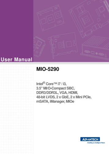
Chipset: Intel Gen 3.5 DX9, MPEG2 Decode in HWDisplay Memory: Optimized Shared Memory Architecture up to 224 MB systemmemoryVGA Resolution: Supports up to 1400 x 1050 @ 60 Hz1.2.4 EthernetChipset: Intel 82567VSpeed: 10/100/1000 MbpsInterface: 1 x RJ45Standard: Compliant with IEEE 802.3, IEEE 802.3u, IEEE 802.3x, IEEE 8023y,IEEE 802.ab.1.2.5 Power Consumption Typical: 12 WMax.: 17 W1.3 Mechanical Specification1.3.1 Dimensions133.8 x 43.1 x 94.2 mm (5.27" x 1.70" x 3.71")94,20 43,1133,80Figure 1.1 ARK-1120 mechanical dimension drawing1.3.2 Weight 0.7 kg (1.55 lb)3ARK-1120 User ManualGeneral Introduction Chapter 11.2.3 Display
1.4 Power requirement1.4.1 System power Minimum power input: DC 12 V 3 A1.4.2 RTC battery 3 V/210 mAh1.5 Environmental Specifications1.5.1 Operating temperature 0 40 C (32 104 F), when air flow speed 0.7 m/sec1.5.2 Relative Humidity 95% @ 40 C (non-condensing)1.5.3 Storage Temperature -40 85 C (-40 185 F)1.5.4 Vibration loading during operation With Compact Flash / 2.5" SATA SSD only: 3 Grms, IEC 60068-2-64, random, 5 500 Hz, 1 Oct./min, 1 hr/axis1.5.5 Shock during operation With Compact Flash / 2.5" SATA SSD only: 30 G, IEC 60068-2-27, half sine, 11ms duration1.5.6 Safety UL, CCC, BSMI1.5.7 EMC CE, FCC, CCC, BSMIARK-1120 User Manual4
Chapter22Hardware installationThis chapter introduces externalIO and the installation ofARK-1120 Hardware.
2.1 IntroductionThe following sections show the internal jumper settings and the external connectorsand pins assignment for applications.2.2 Jumpers2.2.1 Jumper listTable 2.1: Jumper ListJ1AT / ATX Power Selection2.2.2 Jumper SettingsTable 2.2: J1: AT / ATX Power SelectionPart Number1653003260FootprintHD 3x2P 79DescriptionPIN HEADER 3*2P 180D(M) 2.0mm SMD SOUARE PINSettingFunction(5-6) ONAT power*(5-6) EmptyATX power* Default setting2.2.3 Jumper DescriptionCards can be configured by setting jumpers. A jumper is a metal bridge used to closean electric circuit. It consists of two metal pins and a small metal clip (often protectedby a plastic cover) that slides over the pins to connect them. To close a jumper, youconnect the pins with the clip. To open a jumper, you remove the clip. Sometimes ajumper will have three pins, labeled 1, 2 and 3. In this case you would connect eitherpins 1 and 2, or 2 and 3.The jumper settings are schematically depicted in this manual as follows.A pair of needle-nose pliers may be helpful when working with jumpers. If you haveany doubts about the best hardware configuration for your application, contact yourlocal distributor or sales representative before you make any changes.ARK-1120 User Manual6
Warning! To avoid damaging the computer, always turn off the power supplybefore setting jumpers. Clear CMOS. Before turning on the power supply, set the jumper back to 3.0 V Battery On.Chapter 2Generally, you simply need a standard cable to make most connections.2.3 ARK-1120 I/O IndicationHardware installationARK-1120LFigure 2.1 ARK-1120L front viewFigure 2.2 ARK-1120L rear viewARK-1120FFigure 2.3 ARK-1120F front view7ARK-1120 User Manual
Figure 2.4 ARK-1120F rear view2.4 ARK-1120L External I/O Connectors2.4.1 Power ON/OFF ButtonARK-1120 comes with a Power On/Off button with LED indicators on the front side toshow its On status (Green LED) and Off/Suspend status (Orange LED). Dual functions of Soft Power -On/Off (Instant off or Delay 4 Seconds), and Suspend are supported.Figure 2.5 Power ON/OFF Button2.4.2 Power Input ConnectorARK-1120 comes with a Ψ2.5 DC-Jack header that carries 12 VDC external powerinput. The power connector can be fixed by a bracket which is in the accessory box.The bracket makes the power connector very secure.Figure 2.6 Power Input Connector2.4.3 Ethernet Connector (LAN)ARK-1120 provides one RJ45 LAN interface connector which is fully compliant withIEEE 802.3u 10/100/1000 Mbps CSMA/CD standards. It is equipped with 82567V.The Ethernet port uses a standard RJ-45 jack connector with LED indicators on thefront side to show Active/Link status and Speed status.81Figure 2.7 Ethernet ConnectorARK-1120 User Manual8
Chapter 2Table 2.3: Ethernet Connector Pin Assignments10/100/1000 Mbps Signal Name1TX , MDI0 2TX-, MDI0-3RX , MDI1 4MDI2 5MDI2-6RX-, MDI1-7MDI3 8MDI3-Note!NC, if present, represents “No Connection”.2.4.4 VGA ConnectorThe ARK-1120 provides a high resolution VGA interface connected by a D-sub 15pin connector to support a VGA CRT monitor. It supports display resolution up to1400 x 1050 @ 60 Hz.510151611Figure 2.8 VGA ConnectorTable 2.4: VGA Connector Pin AssignmentsPinSignal NamePinSignal 12DDC Date13H-SYNC14V-SYNC15DDC Clock2.4.5 USB ConnectorsThe ARK-1120 provides up to four USB interface connectors, which give completePlug & Play and hot swapping for up to 127 external devices. The USB interface iscompliant with USB UHCI, Rev. 2.0. The USB interface supports Plug and Play,which enables you to connect or disconnect a device whenever you want, withoutturning off the computer.9ARK-1120 User ManualHardware installationPin
Figure 2.9 USB ConnectorTable 2.5: USB Connector Pin AssignmentsPinSignal NamePinSignal Name1VCC2USB data-3USB data 4GND2.4.6 Audio Connector (ARK-1120L Only)ARK-1120 offers stereo audio ports by two 3.5Ψ ear phone jack connectors ofLine out and Line in. The audio chip controller is ALC892 which is compliant withthe Azalea standard.12Figure 2.10 Audio ConnectorsTable 2.6: DIO Connector Pin AssignmentsPinSignal Name1Line-out2Line-in2.4.7 COM ConnectorARK-1120L provides two D-sub 9-pin connectors, which offers RS-232 serial communication interface.ARK-1120F provides four D-sub 9-pin connectors, which offers RS-232/422/485serial communication inter face. Default setting is RS-232, and the mode of serialports are controlled by relay IC. If you would like to use RS-422/485, just needchange the BIOS setting. You can find the detail BIOS setting of serial ports in Chapter 3.Figure 2.11 COM Port ConnectorARK-1120 User Manual10
RS-232RS-422RS-485PinSignal NameSignal NameSignal Name1DCDTx-DATA-2RxDTx DATA 3TxDRx CNote!NC represents “No Connection”.2.5 Peripheral Installation2.5.1 HDD Installation1.Unscrew the bottom cover screws. (marked with "HDD")11ARK-1120 User ManualHardware installation4Chapter 2Table 2.7: COM Connector Pin Assignments
2.Remove the four SNAP RIVETs from the bottom cover.3.Secure 2.5" SATA HDD onto the bottom cover. The screws are in the accessorybox.ARK-1120 User Manual12
Chapter 2Connect SATA signal and power cable to the 2.5" SATA HDD.13ARK-1120 User ManualHardware installation4.
5.Secure the bottom cover in its original position.2.5.2 RAM Installation1.Unscrew the four screws on bottom cover. (marked with "RAM")ARK-1120 User Manual14
Unscrew the four screws on the sides of ARK-1120.3.Unscrew the four screws on the front/rear face plate of ARK-1120.ARK-1120 User ManualHardware installation15Chapter 22.
4.Remove aluminum top chassis and install RAM.5.Replace the aluminum top chassis and secure all screws.2.5.3 CF InstallationPlease refer servicing to qualified Advantech personnel. Use only Advantech CTOSservice or T-Parts OEM.ARK-1120 User Manual16
Chapter33BIOS SettingsThis chapter introduces how toset BIOS configuration data.
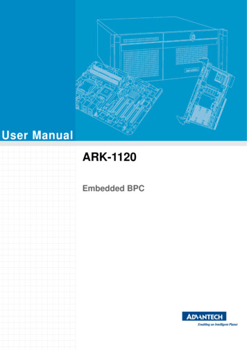
AMIBIOS has been integrated into a plethora of motherboards for over a decade.With the AMIBIOS Setup program, you can modify BIOS settings and control the various system features. This chapter describes the basic navigation of the ARK-1120BIOS setup screens.AMI's BIOS ROM has a built-in setup program that allows the user to modify thebasic system configuration. This information is stored in battery-backed CMOS so itretains the setup information when the power is turned off.3.1 Entering SetupTurn on the computer and check for the “patch" code. If there is a number assignedto the patch code, it means that the BIOS supports your CPU. If there is no numberassigned to the patch code, please contact an Advantech application engineer toobtain an up-to-date patch code file. This will ensure that your CPU's system status isvalid. After ensuring that you have a number assigned to the patch code, press DEL and you will immediately be allowed to enter setup.Figure 3.1 Setup Program Initial ScreenARK-1120 User Manual18
When you first enter the BIOS Setup Utility, you will enter the Main setup screen. Youcan always return to the Main setup screen by selecting the Main tab. There are twoMain Setup options. They are described in this section. The Main BIOS Setup screenis shown below.Chapter 33.1.1 Main SetupBIOS SettingsFigure 3.2 Main Setup ScreenThe Main BIOS setup screen has two main frames. The left frame displays all theoptions that can be configured. Grayed-out options cannot be configured; options inblue can. The right frame displays the key legend.Above the key legend is an area reserved for a text message. When an option isselected in the left frame, it is highlighted in white. Often a text message will accompany it.3.1.1.1 System Time / System DateUse this option to change the system time and date. Highlight System Time or System Date using the Arrow keys.
Cautions are included to help you avoid damaging hardware or losing data. Note! . cuit. There is a danger of explosion if battery is incorrectly replaced. Replace . 1960052227N001 VESA/Desk mounting plate for ARK-1120 WIFI-115E Wireless IEEE 802.11b/g/n, Half-size Mini-PCIe interface WLAN .