Transcription
BACnet Option ModuleInstruction ManualTR200Literature Order NumberDateSupersedesBAS-SVX24A-ENJune 2009www.trane.comFor more information, contact your local Traneoffice or e-mail us at comfort@trane.comTrane has a policy of continous product and product data improvement and reserves the right tochange design and specifications without notice.November 2009130R0451MG12L122*MG12L122*Rev. 2009-06-18
Table of ContentsSafety1-1Copyright, limitation of liability and revision rights1-1High Voltage Warning1-3Before Commencing Repair Work1-8Special Conditions1-8IntroductionIntroductionHow to Install2-12-13-1The BACnet Option3-1System Specifications3-5How to Configure the System4-1Configuring BACnet4-1BIBBs4-2Example of a simple set-up of BACnet4-3How to Control the Adjustable Frequency Drive5-1Network Adjustable Frequency Drive Control Inputs and Out5-2putsAdjustable Frequency Drive Feedback to NetworkParameters5-156-1Parameter Overview6-1Parameter Description6-2TroubleshootingAlarm, Warning and Extended Status Word7-17-1Alarm Words7-2Warning Words7-3TR200 BACnet-1
LED Status-27-4TR200 BACnet
SafetyCopyright, limitation of liability and revision rightsThis publication contains information proprietary to Trane. By accepting and using this manual, the user agreesthat the information contained herein will be used solely for operating equipment from Trane or equipmentfrom other vendors provided that such equipment is intended for communication with Trane equipment overa serial communication link. This publication is protected under the copyright laws of most countries.Trane does not warrant that a software program produced according to the guidelines provided in this manualwill function properly in every physical, hardware or software environment.Although Trane has tested and reviewed the documentation within this manual, Trane makes no warranty orrepresentation, neither expressed nor implied, with respect to this documentation, including its quality, performance, or fitness for a particular purpose.In no event shall Trane be liable for direct, indirect, special, incidental, or consequential damages arising out ofthe use, or the inability to use information contained in this manual, even if advised of the possibility of suchdamages. In particular, Trane is not responsible for any costs, including but not limited to those incurred as aresult of lost profits or revenue, loss or damage of equipment, loss of computer programs, loss of data, the coststo substitute these, or any claims by third parties.Trane reserves the right to revise this publication at any time and to make changes to its contents without priornotice or any obligation to notify former or present users of such revisions or changes.TR200 BACnet1-1
SafetyWarnings, Cautions and NoticesNote that warnings, cautions and notices appear at appropriate intervals throughout this manual. Warnings areprovided to alert installing contractors to potential hazards that could result in personal injury or death. Cautionsare designed to alert personnel to hazardous situations that could result in personal injury, while notices indicatea situation that could result in equipment or property damage-only accidents.Your personal safety and the proper operation of this machine depend upon the strict observance of theseprecautions.Warnings, Cautions and Notices appear at appropriate sections throughout this literature. Read these carefully.WARNINGIndicates a potentially hazardous situation which, if not avoided, could result in death or serious injury.CAUTIONIndicates a potentially hazardous situation which, if not avoided, could result in minor or moderate injury. It could alsobe used to alert against unsafe practices.NOTEIndicates a situation that could result in equipment or property damage-only accidents.NoteIndicates something important to be noted by the reader. 1-2Indicates default settingTR200 BACnet
SafetyHigh Voltage WarningWARNINGThe voltage of the adjustable frequency drive is dangerous whenever it is connected to line power. Incorrect installationof the motor or adjustable frequency drive could result indeath, serious injury or damage to the equipment. Consequently, it is essential to comply with the instructions in this manual as well as local and national rules and safetyregulations.Safety NoteWARNINGThe voltage of the adjustable frequency drive is dangerous whenever connected to line power. Incorrect installation ofthe motor, adjustable frequency drive or serial communication bus could result in death, serious personal injury ordamage to the equipment. Consequently, the instructions in this manual, as well as national and local rules and safetyregulations, must be complied with.WARNINGFailure to follow instructions below could result in death or serious injury.Safety Regulations1. The adjustable frequency drive must be disconnected from line power if repair work is to be carried out.Make sure that the line power supply has been disconnected and that the necessary time has passed beforeremoving motor and line power plugs.2.The [STOP/RESET] key on the keypad of the adjustable frequency drive does not disconnect the equipmentfrom line power and is thus not to be used as a safety switch.3.Correct protective grounding of the equipment must be established, the user must be protected againstsupply voltage, and the motor must be protected against overload in accordance with applicable nationaland local regulations.4.The ground leakage currents are higher than 3.5 mA.5.Protection against motor overload is set by par.1-90 Motor Thermal Protection. If this function is desired,set par.1-90 Motor Thermal Protection to data value [ETR trip] (default value) or data value [ETR warning].Note: The function is initialized at 1.16 x rated motor current and rated motor frequency. For the NorthAmerican market: The ETR functions provide class 20 motor overload protection in accordance with NEC.6.Do not remove the plugs for the motor and line power supply while the adjustable frequency drive is connected to line power. Make sure that the line power supply has been disconnected and that the necessarytime has passed before removing motor and line power plugs.7.Please note that the adjustable frequency drive has more voltage inputs than L1, L2 and L3, when loadsharing (linking of DC intermediate circuit) and external 24 Vdc have been installed. Make sure that allvoltage inputs have been disconnected and that the necessary time has passed before commencing repairwork.TR200 BACnet1-3
SafetyInstallation at high altitudesWARNINGInstallation at high altitude:380–500 V, enclosure A, B and C: At altitudes above 6,561 ft [2 km], please contact Trane regarding PELV/Class II.380–500 V, enclosure D, E and F: At altitudes above 9,842 ft [3 km], please contact Trane regarding PELV/Class II.If the drive is to be installed over 6,561 ft [2 km] altitude, then the PELV specifications are not fulfilled anymore, i.e.,the distances between components and critical parts become too small. To maintain the clearance for functional insulation anyway, the risk for overvoltage must be reduced by means of external protective devices or some kind of galvanicisolation. De-rating should also be taken into consideration, since cooling the drive is more difficult at high altitude.Please contact Trane in such cases.Failure to follow recommendations could result in death or serious injury.WARNINGWarning against Unintended Start1.The motor can be brought to a stop by means of digital commands, bus commands, references or a local stop,while the adjustable frequency drive is connected to line power. If personal safety considerations make it necessaryto ensure that no unintended start occurs, these stop functions are not sufficient.2.While parameters are being changed, the motor may start. Consequently, the stop key [STOP/RESET] must alwaysbe activated, following which data can be modified.3.A motor that has been stopped may start if faults occur in the electronics of the adjustable frequency drive, or if atemporary overload or a fault in the supply line power or the motor connection ceases.Consequently, disconnect all electric power, including remote disconnects before servicing. Follow proper lockout/tagout procedures to ensure the power cannot be inadvertently energized. Failure to follow recommendations couldresult in death or serious injury.WARNINGTouching the electrical parts could result in death or serious injury - even after the equipment has been disconnectedfrom line power.Also make sure that other voltage inputs have been disconnected, such as external 24 VDC, load sharing (linkageof DC intermediate circuit), as well as the motor connection for kinetic backup. Refer to the Instruction Manualfor further safety guidelines.Failure to follow recommendations could result in death or serious injury.WARNINGThe adjustable frequency drive DC link capacitors remain charged after power has been disconnected. To avoid anelectrical shock hazard, disconnect the adjustable frequency drive from line power before carrying out maintenance.Wait at least as follows before doing service on the adjustable frequency drive:Failure to follow recommendations could result in death or serious injury.1-4TR200 BACnet
SafetyVoltage (V)Min. Waiting Time (Minutes)15203040200 - 2407.5–60 hp[5.5 –45 kW]380 - 48015–125 hp150–350 hp450–1350 hp[11–90 kW][110–250 kW][315–1000 kW]525-60015–125 hp[11–90 kW]525-69015–125 hp60–550 hp600–1875 hp[11–90 kW][45–400 kW][450–1400 kW]Be aware that there may be high voltage on the DC link even when the LEDs are turned off.41.5–5 hp[1.1–3.7 kW]1.5–10 hp[1.1–7.5 kW]1.5–10 hp[1.1–7.5 kW]TR200 BACnet1-5
SafetySafety PrecautionsWARNINGThe voltage of the adjustable frequency drive is dangerous whenever connected to line power. Incorrect installation ofthe motor, adjustable frequency drive or serial communication bus could cause death, serious personal injury or damageto the equipment. Consequently, the instructions in this manual, as well as national and local rules and safety regulations, must be complied with.WARNINGSafety Regulations1. The line power supply to the adjustable frequency drive must be disconnected whenever repair work is to becarried out. Make sure that the line power supply has been disconnected and that the necessary time has elapsedbefore removing motor and line power supply plugs.2.The [OFF] button on the control panel of the adjustable frequency driver does not disconnect the line power supplyand consequently it must not be used as a safety switch.3.The equipment must be properly grounded, the user must be protected against supply voltage and the motor mustbe protected against overload in accordance with applicable national and local regulations.4.The ground leakage current exceeds 3.5 mA.5.Protection against motor overload is not included in the factory setting. If this function is desired, set par.1-90 Motor Thermal Protection to data value ETR trip 1 [4] or data value ETR warning 1 [3].6.Do not remove the plugs for the motor and line power supply while the adjustable frequency drive is connectedto line power. Make sure that the line power supply has been disconnected and that the necessary time has elapsedbefore removing motor and line power plugs.7.Please note that the adjustable frequency drive has more voltage sources than L1, L2 and L3, when load sharing(linking of DC intermediate circuit) or external 24 V DC are installed. Make sure that all voltage sources have beendisconnected and that the necessary time has elapsed before commencing repair work.Failure to follow recommendations could result in death or serious injury.WARNINGWarning against unintended start1. The motor can be brought to a stop by means of digital commands, bus commands, references or a local stop,while the adjustable frequency drive is connected to line power. If personal safety considerations (e.g., risk ofpersonal injury caused by contact with moving machine parts following an unintentional start) make it necessaryto ensure that no unintended start occurs, these stop functions are not sufficient. In such cases, the line powersupply must be disconnected or the Safe Stop function must be activated.2.The motor may start while setting the parameters. If this means that personal safety may be compromised (e.g.,personal injury caused by contact with moving machine parts), motor starting must be prevented, for instance byuse of the Safe Stop function or secure disconnection of the motor connection.3.A motor that has been stopped with the line power supply connected, may start if faults occur in the electronicsof the adjustable frequency drive, through temporary overload or if a fault in the power supply grid or motor connection is remedied. If unintended start must be prevented for personal safety reasons (e.g., risk of injury causedby contact with moving machine parts), the normal stop functions of the adjustable frequency drive are not sufficient. In such cases, the line power supply must be disconnected or the Safe Stop function must be activated.Consequently, disconnect all electric power, including remote disconnects before servicing. Follow proper lockout/tagout procedures to ensure the power cannot be inadvertently energized. Failure to follow recommendations couldresult in death or serious injury.1-6TR200 BACnet
SafetyDisconnect all electric power, including remote disconnects before servicing. Follow proper lockout/tagout procedures to ensure the power cannot be inadvertently energized. Failure to follow recommendations could resultin death or serious injury.1.Control signals from, or internally within, the adjustable frequency drive may in rare cases be activated inerror, be delayed or fail to occur entirely. When used in situations where safety is critical, e.g., when controlling the electromagnetic brake function of a hoist application, these control signals must not be reliedon exclusively.NoteWhen using the Safe Stop function, always follow the instructions in the Safe Stop section of the Design Guide.WARNINGDisconnect all electric power, including remote disconnects. Follow proper lockout/tagout procedures to ensure thepower cannot be inadvertently energized. Use an appropriate voltmeter to verify that the unit is discharged. Failure todisconnect power and ensure unit is discharged before servicing could result in death or serious injury.Also make sure that other voltage inputs have been disconnected, such as external 24 V DC, load sharing (linkage ofDC intermediate circuit), as well as the motor connection for kinetic backup.Systems where adjustable frequency drives are installed must, if necessary, be equipped with additional monitoringand protective devices according to the valid safety regulations, e.g., law on mechanical tools, regulations for theprevention of accidents, etc. Modifications on the adjustable frequency drives by means of the operating software areallowed.Failure to follow recommendations could result in death or serious injury.Hoisting applications:The adjustable frequency drive functions for controlling mechanical brakes cannot be considered as a primarysafety circuit. There must always be a redundancy for controlling external brakes.Protection ModeOnce a hardware limit on motor current or DC link voltage is exceeded, the drive will enter “Protection mode”.“Protection mode” means a change of the PWM modulation strategy and a low switching frequency to minimizelosses. This continues 10 sec after the last fault and increases the reliability and the robustness of the drive whilere-establishing full control of the motor.In hoist applications, “Protection mode” is not usable because the drive will usually not be able to leave thismode again, and therefore it will extend the time before activating the brake – which is not recommended."Protection mode” can be disabled by setting par.14-26 Trip Delay at Inverter Fault to zero, which means thatthe drive will trip immediately if one of the hardware limits is exceeded.NoteIt is recommended to disable protection mode in hoisting applications (par.14-26 Trip Delay at Inverter Fault 0).TR200 BACnet1-7
SafetyBefore Commencing Repair WorkWARNINGHazardous Voltage!1.Disconnect the adjustable frequency drive from line power.2.Disconnect DC bus terminals 88 and 893.Wait at least the time mentioned above in the section General Warning.4.Remove motor cableFailure to follow recommendations could result in death or serious injury.Special ConditionsElectrical ratings:The rating indicated on the nameplate of the adjustable frequency drive is based on a typical 3-phase line powersupply within the specified voltage, current and temperature ranges, which are expected to be used in mostapplications.The adjustable frequency drives also support other special applications, which affect the electrical ratings of theadjustable frequency drive.Special conditions that affect the electrical ratings might be: Single phase applications. High temperature applications that require derating of the electrical ratings. Marine applications with more severe environmental conditions.Other applications might also affect the electrical ratings.Consult the relevant sections in this manual and in the for information about the electrical ratings.Installation requirements:The overall electrical safety of the adjustable frequency drive requires special installation considerations regarding: Fuses and circuit breakers for overcurrent and short-circuit protection Selection of power cables (line power, motor, brake, load sharing and relay) Grid configuration (grounded delta transformer leg, IT,TN, etc.) Safety of low-voltage ports (PELV conditions).Consult the relevant clauses in these instructions and in the for information about the installation requirements.1-8TR200 BACnet
IntroductionIntroductionAbout this ManualFirst time users can obtain the most essential information for quick installation and set-up in these chapters:IntroductionHow to InstallHow to Configure the SystemApplication ExampleFor more detailed information including the full range of set-up options and diagnosis tools, refer to the chapters:How to Control the TR200How to Access TR200 ParametersParametersTroubleshootingTechnical OverviewBACnet (Building Automation and Control Network) is an open data communications protocol, American National Standard (ANSI/ASHRAE 135-1995). BACnet provides a means by which computer-based control equipment from different manufacturers can work together. BACnet is designed to handle many types of buildingcontrols, including HVAC, lighting, security, fire, access control, maintenance and waste management. BACnetpermits flexibility for expansion and different equipment combinations.Conformance Classes, Function Groups and the PICS: Evaluating the capabilities of a BACnet device is potentially a formidable task, given the great choice of objects, properties and services, which can be implemented,as well as the fact that it is not necessary for every BACnet device to have a full BACnet implementation in orderto carry out its task. ASHRAE's BACnet Committee recognized this problem and responded with aids to evaluation in the form of "Conformance Classes", "Function Groups" and the "Protocol Implementation ConformanceStatement" (PICS).The BACnet protocol defines six levels of conformance classes, each of which specifies the minimum subset ofservices implemented on the device. The lowest level, Conformance Class 1, requires only that the BACnetdevice contain a device object and that it be able to execute (respond to) a ReadProperty service request. Eachsuccessive conformance class level adds service requests that must be executable by the device, as well as theservice requests it must be able to initiate. Conformance Class 6 requires 21 types of service requests (of the 32overall) to be implemented, of which 20 must be initiable and 17 executable. Conformance class thus providesa measure of the device's ability to communicate.Function groups specify a combination of objects and services necessary to carry out certain building automation functions. They are specified independently of conformance class, though the implementation of some ofthe function groups automatically confers some conformance class higher than 1.TR200 BACnet2-1
IntroductionBackground informationProtocol name:Technology developer:Year introduced:Governing standards:Openness:BACnetASHRAE1995ANSI/ASHRAE Standard 135-2004, ISO 16484-5Open specificationPhysical characteristicsNetwork topology:Physical media:Max. Distance at low speed:BusShielded twisted pair3937 ft [1200 m]Transport mechanismCommunication methods:Baud Rates Supported:Termination:Master/slave9600, 19200, 38400, 76800120 ohm2-2TR200 BACnet
IntroductionAssumptionsThis manual assumes you are using a Trane BACnet Option Card in conjunction with a Trane TR200 seriesadjustable frequency drive. It is also assumed that your master is a BMS or PC equipped with a serial communication card supporting all the BACnet communication services required by your application, and that allrequirements stipulated in the BACnet standard, as well as those pertaining to the Variable Frequency Drive arestrictly observed as well as all limitations therein fully respected.Background KnowledgeThe Trane BACnet Option Card is designed to communicate with any master complying with the BACnet standard. Familiarity with the PC or PLC used as a master in the system is assumed. Issues regarding hardware orsoftware produced by other manufacturers are beyond the scope of this manual and are not the responsibilityof Trane.If you have questions regarding set-up of master-to-master communication or communication to a non-Traneslave, consult the appropriate manuals.Available Literature for TR200-The Instruction Manual provides the necessary information for getting the drive up and running.-Instruction Manual TR200 High Power-The Design Guide contains all the technical information about the drive and customer design and applications.-The Programming Guide provides information on how to program and includes complete parameter descriptions.x Revision numberyy Language codeTrane technical literature is available in print from your local Trane Sales Office or online at: www.trane.com/vfdTR200 BACnet2-3
EIAAcyclical Control IntervalApplication Orientated ControllerAnalog VariableBuilding Management SystemBinary VariableController Area NetworkControl WordElectrical Erasable Programmable Read OnlyMemoryElectronic Industries Association: Specifies of theEIA Standard RS 485-AEMCElectromagnetic CompatibilityFDLSerial Communication Bus Data link LayerFDTField Device ToolINDSub indexI/OInput/OutputISOInternational Standards OrganizationLCDLiquid Crystal Displaykeypad Local Control PanelLEDLight Emitting DiodeMAVMain Actual ValueMOCMotion Orientated ControllerMRVMain Reference ValuePCPersonal Computer2-4PCDPCAPCVPDUPELVPLCPNUPVAProcess DataParameter ocol Data UnitProtected Extra Low VoltageProgrammable Logic ControlParameter NumberParameter ValueRCRequest/Response CharacteristicsSTWStatus WordTR200 BACnet
How to InstallThe BACnet OptionInstallation of the OptionItems required to install a serial communication bus option in the adjustable frequency drive:-The serial communication bus option-Serial communication bus option adaptor frame for the adjustable frequency drive. This frame is deeperthan the standard frame, to allow space for the serial communication bus option beneath.-Cable holdersTR200 BACnet3-1
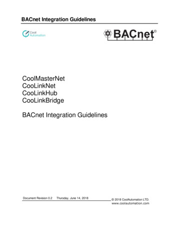
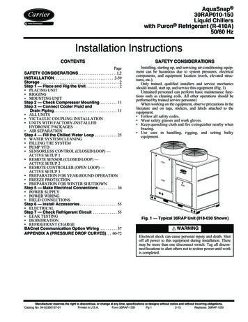
How to InstallInstructions:Remove the keypad panel from the adjustable frequency drive.-Remove the frame located beneath and discard.-Push the option into place. Two positions are possible, with cable terminal facing either up or down. Thecable up position is often most suitable when several adjustable frequency drives are installed side by sidein a rack, as this position permits shorter cable lengths.-Push the serial communication bus option adaptor frame for the adjustable frequency drive into place.-Remove the plug for the Drive port and connect the plug that is connected to the BACnet option-Replace the keypad panel.-Attach cable.-Fasten the cable in place using cable holders. The adjustable frequency drive top surface has pre-drilledthreaded holes for attaching the cable holders to the unit.130BT341.10-CablingCable lengths and number of nodesThe maximum cable length allowable in one segment is dependent on the transmission speed. The total cablelength includes drop cables if any. A drop cable is the connection from the main bus cable to each node. If a Tconnection is used, permissible cable length and maximum number of nodes/drives are 1, 2, 3 and 4 bussegments.Drop cable connection (i.e., T-connection) beyond the cable lengths indicated is not recommended, due to theincreased risk of reflection occurring. Instead, Trane recommends direct connection of the adjustable frequencydrive.Note that a repeater is a node in both of the two segments it connects. The number of adjustable frequencydrives is based on a single master system. If there are two or more masters (e.g., PC tools, routers), the numberof adjustable frequency drives must be reduced correspondingly.Network topologyFree topology without repeaterFree topology with one repeaterFree topology maximum device-to-deviceBus topology single terminatedBus topology double terminated without repeaterBus topology double terminated with one repeaterBus topology maximum stub length3-2Maximum cable length1640 ft [500 m]3280 ft [1000 m]1640 ft [500 m]1640 ft [500 m]8858 ft [2700 m]17716 ft [5400 m]9.8 ft [3 m]TR200 BACnet
How to InstallThe length statements in the tables above are valid for bus cable with the following properties:-Impedance: 135 to 165 Ohm at a measuring frequency from 3 to 20 MHz-Resistance: 110 Ohm/km-Capacitance: 30 pF/m-Damping: max. 9 dB over the whole wire length-Cross section: max. 0.00053 in2 [0.34 mm2], corresponding to AWG 22-Cable type: twisted in pairs, 1 x 2, or 2 x 2, or 1 x 4 wires-Shielding: Copper-braided shield or braided shield and foil shieldUse of the same cable type throughout the entire segment is recommended to avoid impedance mismatch.TR200 BACnet3-3
How to InstallNetwork TerminationConnecting the Bus LineConnect the BACnet Option Card to the bus line via terminals 62, 63 and 66. Terminal 62 is marked red andTerminal 63 is marked green. These two are the RS485 lines. Terminal 66 the signal ground for the RS485transmitter.Maximum Cable LengthsMaximum total bus cable length: 4000 ft [1200 m]3-4TR200 BACnet
How to InstallCable RoutingThe BACnet communication cable must be kept away from motor and brake resistor cables to avoid couplingof high frequency noise from one cable to the other. Normally a distance of 7.9 in (200 mm) is sufficient, butmaintaining the greatest possible distance between cables is generally recommended, especially where cablesrun in parallel over long distances.When crossing is unavoidable, the BACnet cable must cross motor and brake resistor cables at an angle of 90degrees.System SpecificationsEMC PrecautionsThe following EMC precautions are recommended to achieve interference-free operation of the BACnet network.Additional EMC information is available in the TR200 Drive Design Guide. Also consult the BACnet master manualfor further installation guidelines.NOTEEnsure compliance with relevant national and local regulations, for example in protective ground connection.Connection of the Cable ShieldIt is recommended to connect the shield to ground at both ends of the bus cable. This ensures the optimumresistance towards EMC noise. The shield of the BACnet cable must always be connected to ground at bothends, meaning the shield must be connected to ground in all stations connected to the BACnet network. It isvery important to have a low impedance ground connection of the shield, also at high frequencies. This can beobtained by connecting the surface of the shield to ground, for example by means of a cable clamp or a conductive cable connector. The TR200 Series has various clamps and brackets to enable a proper groundconnection of the BACnet cable shield.TR200 BACnet3-5
How to InstallGround ConnectionIt is important that all stations connected to the BACnet network are connected to the same ground potential.The ground connection must have low HF (high frequency) impedance. This can be achieved by connecting alarge surface area of the cabinet to ground, for example by mounting the TR200 series on a conductive rearplate. Particularly when there are long distances between the stations in a BACnet network, it may be necessaryto use additional potential equalizing cables, connecting the individual stations to the same ground potential.The use of repeaters with galvanic isolation or fiber optic can improve the EMC performance and reduce groundloop current.3-6TR200 BACnet
How to Configure the SystemConfiguring BACnetInitialization ProcedureThe Initialization Procedure is explained by the flow chart given below:Initialization ParameterGeneral SettingsNameControl SiteControl word sourceControlWord Timeout timeControlWord Timeout FunctionEnd of Timeout FunctionReset ControlWord TimeoutDiagnosisControlWord ProfilePar. Number8-018-028-038-048-058-068-078-10Default ValueDigital and control wordDrive RS-4851.0 secOffResume set-upDo not resetSet-upDrive ProfileSetting for BACnetDigital and control wordDrive RS-4851.0 secOffResume set-upDo not resetDon’t careDrive ProfilePar. Number8-308-318-328-358-36Default ValueDrive19600 baud10 ms5000 msSetting for BACnetDrive Option19600 baud10 ms5000 msDrive Port SettingsNameProtocolAddressBaud RateMinimum Response DelayMax Response DelayTable 4. 1: 1) Please see also section: Parameter Overview Parameter Lis
Instruction Manual November 2009 TR200 BAS-SVX24B-EN Trane has a policy of continous product and product data improvement and reserves the right to change design and specifications without notice. www.trane.com For more information, contact your local Trane office or e-mail us at comfort@trane.com Literature Order Number BAS-SVX24A-EN