Transcription
BROOKFIELD DIGITAL RHEOMETERMODEL DV-III Operating InstructionsManual No. M/98-211-A0701Please record the Model and Serial Number of your viscometer.Having this information readily available will help us to assist youshould there be any questions regarding your instrument.Model No.Serial No.SPECIALISTS IN THEMEASUREMENT ANDCONTROL OF VISCOSITYBROOKFIELD ENGINEERING LABORATORIES, INC.11 Commerce Boulevard, Middleboro, MA 02346-1031 USATEL 508-946-6200 or 800-628-8139 (USA excluding MA)FAX 508-946-6262 INTERNET www.brookfieldengineering.comBrookfield Engineering Laboratories, Inc.Page 1Manual No. M/98-211-A0701
ContentsI.INTRODUCTION . 3I.1Components . 4I.2Utilities . 5I.3Specifications . 5I.4Data Retention. 5I.5Set-Up . 6I.6Connections . 9I.7Key Functions . 10II.GETTING STARTED . 12II.1Autozero . 12II.2Rheometer Display . 13II.3Spindle Entry. 15II.4Direct Speed Entry . 16II.5External Control . 17III. MAKING VISCOSITY MEASUREMENTS . 19III.1Quick Start . 19III.2Preparation . 19III.3Selecting a Spindle/Speed . 20III.4Multiple Data Points . 20III.5Cleaning . 20IV. PROGRAMMING THE DV-III AND ANALYSIS . 21IV.1Programming Concept . 21IV.2DV-III Speed/Time Pair Programming . 22IV.3Bevis Programs . 34IV.4Choosing the Best Data Collection Method . 36IV.5Data Analysis . 37V.OPTIONS . 40V.1Set Up . 40V.2Print . 41V.3Alarms . 42V.4Set Temperature . 43V.5Data . 43V.6Timed data collection . 44VI. RHEOLOADER USER'S MANUAL . 47VI.1Description of B.E.V.I.S. Commands . 47VI. 2Example Programs . 50APPENDIX AAPPENDIX BAPPENDIX CAPPENDIX DAPPENDIX EAPPENDIX FAPPENDIX GAPPENDIX HAPPENDIX I- Cone/Plate Rheometer Set-Up . 52- Viscosity Ranges. 56- Variables in Viscosity Measurements . 61- Spindle and Model Codes . 63- Calibration Procedures . 67- VS-27Y Clamp Assembly. 74- DV-III to Computer Command Set . 75- Fault Diagnosis and Troubleshooting . 77- Warranty Repair and Service . 80Brookfield Engineering Laboratories, Inc.Page 2Manual No. M/98-211-A0701
I.INTRODUCTIONThe Brookfield DV-III Programmable Rheometer measures fluid parameters of Shear Stress andViscosity at given Shear Rates. Viscosity is a measure of a fluid’s resistance to flow. You will finda detailed description of the mathematics of viscosity in the Brookfield publication “More Solutionsto Sticky Problems”, a copy of which was included with your DV-III .The principle of operation of the DV-III is to drive a spindle (which is immersed in the test fluid)through a calibrated spring. The viscous drag of the fluid against the spindle is measured by thespring deflection. Spring deflection is measured with a rotary transducer. The measuring range ofa DV-III (in centipoise) is determined by the rotational speed of the spindle, the size and shape ofthe spindle, the container the spindle is rotating in, and the full scale torque of the calibrated spring.There are four basic spring torque series offered by Brookfield:ModelLVDV-III RVDV-III HADV-III HBDV-III Spring Torquedyne cm673.77,187.014,374.057,496.0mN m0.06730.71871.43745.7496The higher the torque calibration, the higher the measurement range. The measurement range foreach torque calibration may be found in Appendix - B.All units of measurement are displayed according to either the CGS system or the SI system.1. Viscosity appears in units of centipoise (shown as “cP”) or milliPascal-seconds (shownas mPa s).2. Shear Stress appears in units of dynes/square centimeter (“D/cm2”) or Newtons/squaremeter (“N/m2”).3. Shear Rate appears in units of reciprocal seconds (“1/SEC”).4. Torque appears in units of dyne-centimeters or Newton-meters (shown as percent “%”in both cases).The equivalent units of measurement in the SI system are calculated using the following conversions:SICGSViscosity:1 mPa s 1 cP 10 dyne/cm2Shear Stress: 1 Newton/m2Torque:1 N m 107 dyne cmReferences to viscosity throughout this manual are done in CGS units.WARNING: Use of this instrument in a manner not specified by Brookfield may result in incorrectreadings or instrument failure. Please read this manual prior to using the instrument.Brookfield Engineering Laboratories, Inc.Page 3Manual No. M/98-211-A0701
I.1 ComponentsComponentPart NumberDV-III Rheometerdepends on modelPowerbaseincludes:Leveling Screws (3)Upright RodJam NutClamp AssemblyDVP-2YVS-3VS-20VS-21VS-27YSpindle Set with CaseLVDV-III set of four spindles orRVDV-III set of seven spindles orHA/HBDV-III set of seven spindlesSSLSSRSSHFor Cone/Plate versions: a spindle wrench, one cone spindle and sample cup Part No.CPE-44Y replace the spindle set.Power Cordfor 115 VACfor 230 VACDVP-65DVP-66RTD Temperature ProbeDVP-94YRibbon CableDVP-145Guard Leg:LVDV-III RVDV-III B-20YB-21YCarrying CaseDVP-71YRHEOLOADER SoftwareDVP-201YCable (DV-III to Computer)DVP-80Operator ManualM/98-211Please check to be sure that you have received all components, and that there is nodamage. If you are missing any parts, please notify Brookfield Engineering or your localBrookfield agent immediately. Any shipping damage must be reported to the carrier.Brookfield Engineering Laboratories, Inc.Page 4Manual No. M/98-211-A0701
I.2 UtilitiesAutosensing Power Supply:Input Voltage:90 - 260 VACInput Frequency:50 - 60 HzPower Consumption: Less than 220 UAPower Cord Color Code:United StatesOutside United StatesBlackWhiteGreenBrownBlueGreen/YellowHot (live)NeutralGround (earth)I.3 SpecificationsSpeed Range:0.01-250 RPM, 0.01 RPM increments from 0.01 to 0.99 RPM,0.1 RPM increments from 1.0 to 250 RPMViscosity Accuracy: 1.0% of full scale range for a specific spindle running at aspecific speed.Temperature sensing range:- 100 C to 300 C (-148 F to 572 F)Temperature accuracy: 1.0 C from -100 C to 150 C 2.0 C from 150 C to 300 CAnalog Torque Output:0 - 1 Volt DC (0 - 100% torque)Analog Temperature Output: 0 - 4 Volts DC (10mv / C)Printer Output:Centronics, serialComputer Interface:RS232Weight:Gross Weight:Net Weight:35 lbs.32 lbs.Carton Volume:2.0 cu. ft.0.057 m315.9 kg14.5 kgI.4 Data RetentionThe DV-III will save spindle parameters (used to calculate centipoise, shear rate and shear stress),default settings and the test data from the last program test run when the rheometer is turned off orthere is a power failure.Brookfield Engineering Laboratories, Inc.Page 5Manual No. M/98-211-A0701
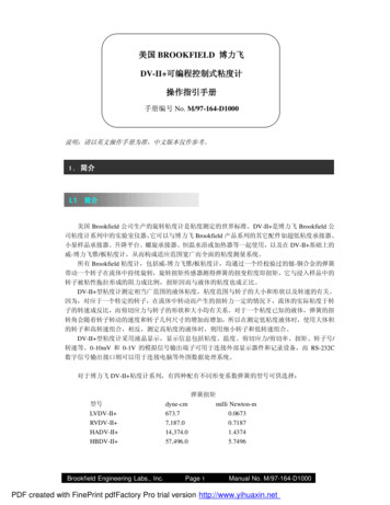
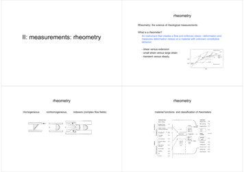
I.5 Set-Up1) Place the upright rod into the hole at the front of the base. The rack gear and clamp assemblyshould face the rear of the base (see Figure 1). The upright rod is held in place with the jam nutwhich is attached from the bottom of the base. Tighten this nut with a suitable wrench (spanner).VS-35UNIVERSALCLAMPVS-40YGEAR SCREWASSEMBLYVS-41YCLAMP 044012E1404-40 x 3/8 LG.SOC. HD. CAP SCREWVS-29WWASHER(2 REQ'D.)VS-34UPRIGHT RODBASE UNIT502020032S34ZWASHER, EXT. TOOTH,5/16 O.D. x 5/32 I.D.50S311B24S06B, SCREW,5/16 - 18x3/8 LG. SLT. PAN HD.Figure 1Brookfield Engineering Laboratories, Inc.Page 6Manual No. M/98-211-A0701
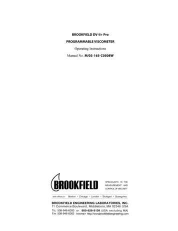
2) Insert the mounting handle on the back of the DV-III into the hole on the clamp assembly(Figure 2).Bubble LevelRack GearClamp ScrewClamp AssemblyUpright RodMounting HandleFigure 23) Tighten the DV-III clamp Screw (Figure 2).Note: If the clamp assembly moves along the upright rod too freely, tighten thetension screw (see Appendix F).4) Insert the ribbon cable into the DV-III Rheometer head. Insert the other end of the ribboncable into the connector on the DV-III base (see Figure 3).Brookfield Engineering Laboratories, Inc.Page 7Manual No. M/98-211-A0701
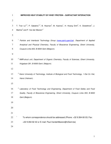
Rheometer HeadRTD TemperatureProbe ConnectorPower ON/OFF SwitchRibbon CableAC Fuse(s)ConnectorRS-232 SerialPrinter/ComputerAnalog Output(s)AC Power Connector100-240 VAC 50/60 HZ 220VAMODEL DV-III BASE UNITConnectorParallel Printer240 CUSTHING ST.STOUGHTON, MA USA 02072ConnectorRibbon CableFigure 35) Connect the RTD probe to the socket on the back side of the DV-III Rheometer (Figure 3).6) The Rheometer must be leveled before the instrument is zeroed and readings are taken. The levelis adjusted using the three leveling screws on the base. Adjust so that the bubble level on top ofthe DV-III (Figure 2) is centered within the circle.7) Make sure that the AC power switch at the rear of the base unit is in the OFF position. Connectthe AC plug to the socket on the back of the DV-III base and plug it into the appropriate AC line.The DV-III must be earth grounded to ensure against electronic failure!!8) Temperature monitoring is assured (after the instrument has stabilized) to within 1.0 C in therange -100 C to 150 C and within 2 C in the range 150 C to 300 C.9) For Cone/Plate models refer to Appendix A.10) For printers, software and temperature controllers, refer to Section 1.6, Connections.Brookfield Engineering Laboratories, Inc.Page 8Manual No. M/98-211-A0701
I.6 ConnectionsThe DV-III Rheometer is capable of communicating with several external devices to enhanceoperation. The cables and connections required for proper communication are detailed below. RHEOLOADER SOFTWAREDVP-80 cable is used to connect the RS232 serial port on the DV-III base to Com Port 1 or ComPort 2 on the computer. This cable is supplied with the DV-III . RHEOCALC SOFTWAREDVP-80 cable is used to connect the RS232 serial port on the DV-III base to Com Port 1 or ComPort 2 on the computer. This cable is supplied with the RHEOCALC software. PARALLEL PRINTERCAP-86 cable is used to connect the 25-pin parallel port on the DV-III base with the Centronicsport on the printer. SERIAL PRINTERDVP-81 cable is used to connect the 9-pin serial port on the DV-III with the 25-pin serial port ona printer. THERMOSEL CONTROLLER, MODEL HT-106TC-200/TC-500/TC-201P/TC-501P BATH, MODEL HT-107DVP-141 cable is used to connect the serial port on the DV-III base to the serial port on thecontroller. This cable is supplied with the controller/bath.Be sure that the controller temperature probe is properly located in the control device (Thermoselor bath) and connected to the controller.Notes:1. The controller may alternately communicate with Rheocalc V 2.0 software. In this configuration, the controller is connected to the computerthrough either Com Port 1 or Com Port 2. The DV-III is also connectedto a computer Com Port.2. The controller must also be connected to the control device (Thermosel orbath) with the appropriate load cable. STRIP CHART RECORDERDVP-96Y cable is used to connect the serial port on the DV-III to the input block of the strip chartrecorder. This cable is supplied with a Brookfield strip chart recorder.Brookfield Engineering Laboratories, Inc.Page 9Manual No. M/98-211-A0701
I.7 Key FunctionsFigure 4 shows the control keys on the face of the DV-III Rheometer. The following describeseach key’s RFigure 4MOTORON/OFFESCAPEAUTORANGEMOTOR ON/OFF, ESCAPETurns the motor on or off. Cancels any operation, returns the user to the previous screen.AUTORANGEPresents the maximum (100% torque) viscosity attainable using the selected spindle atthe current speed.SELECTSPDLSELECT SPDLAllows selection of the spindle to be used.SELECTDISPOPTIONTABSELECT DISPSelects the parameter to be displayed:% Rheometer Torque (%)cP Viscosity (cP or mPa.s)SS Shear Stress (Dynes/cm2 or Newtons/m2)SR Shear Rate (1/Sec)OPTION, TABAccesses options menu. See Section V. Toggles between selectable items when indicated.PRINTPRINTSends a single line of data to an attached printer. Selects printing and non-printing mode asselected in the Options menu.Brookfield Engineering Laboratories, Inc.Page 10Manual No. M/98-211-A0701
PROGPROGAccess the Programs menu for program creation, running or deleting. Contstructs a testprogram. Allows you to review/modify an existing test program. Execute a Bevis program.PROGRUNPROG RUNExecute DV-III speed/time pair program.0NUMBER KEYS (0 through 9)Sets speeds and choose items from various dialog screens and the option menu.ENTERENTERFunctions as an ENTER key similar to a computer by serving to accept a keyboard entry.Brookfield Engineering Laboratories, Inc.Page 11Manual No. M/98-211-A0701
II. GETTING STARTEDII.1 AutozeroBefore readings may be taken, the Rheometer must be autozeroed. This is done each time the powerswitch is turned on. The Rheometer will guide you through the procedure, as follows:Turn power switch on; as shown in Figure 5, the screen indicates that the DV-III is in the standalonemode (is not connected to a computer) and gives the version of the operating firmware (the built inprogram which controls the instrument) and a two-digit alphanumeric code which indicates theModel number (see Table D2 in Appendix D; the code tells the spring torque rating of yourRheometer).Figure 5No key press is necessary. After a short pause the display will read “REMOVE SPINDLE, LEVELRHEOMETER AND PRESS THE MOTOR ON/OFF KEY TO AUTOZERO.” Before beginning the autozeroprocedure, Brookfield recommends that you allow 10 minutes for the instrument to warm up.After pressing the MOTOR ON/OFF key, the screen “flashes” for approximately 15 seconds whilethe DV-III autozeros.After 15 seconds the display reads “AUTOZERO IS COMPLETE REPLACE SPINDLE AND PRESS ANYKEY.” Press a key.The main screen is displayed and the DV-III is ready for use (Figure 6).Figure 6Brookfield Engineering Laboratories, Inc.Page 12Manual No. M/98-211-A0701
II.2 Rheometer DisplayThe DV-III Rheometer is supplied with a 4-line display. The basic set of information is called "TheDefault Screen" and is shown in FIGURE 7. The parameters are detailed below:123456Figure 71. Motor Status and Current Rheometer SpeedThe DV-III motor can be OFF, ON at 0.0 rpm or ON at a speed greater than 0.0 rpm. When themotor is OFF, "OFF" will be displayed and no speed entry will be accepted. When the motor isON, the actual speed of rotation will be displayed. When the motor is switched from ON to OFF,the speed of rotation will be remembered; when the motor is turned ON again, the DV-III willoperate at that same speed. The rheometer motor is set to "OFF" after AUTOZERO.Note: Motor OFF and a speed setting of 0.0 are essentially the same.2. Spindle NumberThe currently-selected spindle. Viscosity, shear rate, and shear stress values will be calculatedbased on this number. See Section II.3.3. Measured TemperatureThe current temperature as measured by the attached temperature probe. If no probe is connected,four dashes "----" will be displayed.4. Printing StatusIndicates the currently-selected method of printing. See Section II.5.5. Measured DataInstrument Torque (%), Viscosity (cP), Shear Stress (D/cm2), Shear Rate (s-1)The parameters are toggled from one to another using the Select Display key.Note: Shear Stress and Shear Rate data cannot be calculated for some spindlegeometries. In these cases, the display will show 0.0.6. Blank LineThis line is used to display entry data when selecting a spindle or speed of rotation. Additionally,selected programs available for running will be identified here when in the Program mode. (SeeSection IV.2).The default screen will appear at the completion of the AUTOZERO sequence each time the DVIII is turned ON in the standalone mode (see Section II.6 for external control mode). The displayeddata may be changed as described in the following sections.The format for data displayed in the default screen and all other screens is described in Table 1. Forappearance sake, the entries in the table have been decimal point aligned. Actual rheometer displaywill have all fields left justified.Brookfield Engineering Laboratories, Inc.Page 13Manual No. M/98-211-A0701
ItemPrintRPMRPMModelSpindleTorqueViscosityMSTcP or mPasShearD/CM2 orN/M2 D/CM2/10StressShear Rate1/SECTemperature TTT ii mm eeZFormatRangeExample0.01 RPM 0.99X.XXXX.X0.1 RPM 99.9XXX.X100 RPM 250See Model Table D2 - App DXXXXX00 S 99XX-10.1 T 99.9XX.XX.XX0 cP 9.99XXX.X10 cP 999.9XXXXX1000 cP 99999XXXeX100000 cP 51200000000X.XX0 D/CM2 9.99XXX.X10 D/CM2 999.9XXXXX1000 D/CM2 99999XXXeX100000 D/CM2 999999X.XXX0 1/SEC 9.999XX.X10 1/SEC 99.9XXXXX100 1/SEC 99999XXX.X-99.9 T 300.0XX:XX00:00 Z 99.590.092.4150.0RV3182.43.16123.812345123e3 to 84.56234.512345123e31.23420.7200-10.305:32Table 1 OUT OF RANGE INDICATORSThe DV-III is capable of measuring instrument torque within the range of 0 to 100%. Based onthis measurment, viscosity and shear stress are calculated. Brookfield recommends that data becollected only in the range of 10 to 100%. Any data collected outside of this range is consideredinvalid.The DV-III provides the following display indicators when the measurement point is outside ofthe 10-100% acceptable range. TORQUE GREATER THAN 100%When Rheometer torque exceeds 100%, the parameter display field will show “EEEE” for torque,viscosity and shear stress.Figure 8 TORQUE LESS THAN 10%When Rheometer torque drops below ten (10) percent, the Rheometer will continue to displaymeasurement (%, cP, D/cm2) values with units flashing:Brookfield Engineering Laboratories, Inc.Page 14Manual No. M/98-211-A0701
Figure 9 TORQUE LESS THAN 0%When Rheometer torque drops below zero (0) percent, the Rheometer will continue to displaytorque values preceded by a minus (-) sign. The viscosity and shear stress field will display dashes(- - - - ) as indicated in the next screen display:Figure 10II.3 Spindle EntryThe user can elect to change the spindle selection by pressing the SELECT SPDL key. The DV-III control program will use the previously blank line 3 on the default display screen to record the newspindle input as depicted in Figure 11.Figure 11To enter a spindle number, press the numeric keys until the desired spindle number has been entered.Valid spindle numbers encompass the range from 00 to 99 as listed in Appendix D. Mistakes arecorrected by repeatedly pressing the numeric keys until the proper spindle value has been entered.At that point, the user presses the SELECT SPDL key again. An invalid spindle entry will result ina “beep” and the display of the data entry error screen as depicted below.Figure 12Brookfield Engineering Laboratories, Inc.Page 15Manual No. M/98-211-A0701
An invalid spindle entry is any two digit number in the range from 01 to 99 which is not listed inAppendix D. This error message will be displayed for a few seconds after which the spindle entryscreen (Figure 11) will be re-displayed with a blank field for the spindle number. The user cancancel spindle entry at any time by pressing the MOTOR ON/OFF/ESCAPE key.The user may elect to use a special spindle whose selection is accomplished by first entering aspindle number of 99 and then pressing the SELECT SPDL key. This will result in the followingdisplay:Figure 13At this point, press the numeric key for the special spindle of choice. This list is created at the timethe Rheometer is manufactured. This list will therefore depend on the number of special spindlesordered and could contain as few as one (1) or as many as five (5) spindles. If no special spindleswere purchased, the following message will be displayed if 99 is entered for a spindle number:Figure 14Press any key to exit this screen and to return to the spindle selection screen. The user may againselect another spindle or press the SELECT SPDL key to cancel spindle selection operation.Successful selection of a spindle at the press of the SELECT SPDL key returns the user to the defaultscreen with the new spindle displayed in the upper right-hand corner. For standard spindles thiswould be the two (2) digit designator used to select the spindle. In the case of special spindles, thetwo (2) letters (AA, AB, AC, AD or AE) corresponding to the special spindle would be displayedinstead. The spindle number or letters will be retained in memory when power is removed. Thismeans that the last value entered for the spindle will be displayed the next time the Rheometer isturned on.II.4 Direct Speed EntryAt this point, the user may choose to enter a speed by the so-called direct speed entry method. Entera valid speed in the range of 0.01 to 250 RPM by pressing the numeric keys successively. Thepreviously blank line 3 on the default display screen records the user’s new speed input as depictedin Figure 15:Brookfield Engineering Laboratories, Inc.Page 16Manual No. M/98-211-A0701
Figure 15Here, the user intends to enter a speed of 112 RPM, has pressed the “1” key twice and is about topress the “2” key. If the user makes more than five (5) key presses, the DV-III control programwill “roll” the cursor back to the first character of the field and begin to overwrite the previous dataentry.Next the user presses the ENTER key to accept the speed. The motor will begin running at 112 RPMand the display will be updated to the next screen image:Figure 16If the speed entered was not valid the Rheometer will display the following message:Figure 17After a few seconds, the display returns to Figure 15 with the speed data field cleared and just theunderscore cursor awaiting a new entry.II.5 External ControlThe DV-III Rheometer can be used in conjunction with Brookfield software, RHEOCALC (V. 2.or higher). Through RHEOCALC, all rheometer functions are controlled by the computer. The DVIII must be set to the external control mode to allow for proper communication with RHEOCALC.To configure the external control mode, connect cable DVP-80 to the serial port on the DV-III basebefore turning on the DV-III . With the DVP-80 cable in place, the DV-III will present the screenshown in Figure 18 when it is turned on. If external control is selected, the DV-III will displayFigure 19 and only accept control commands from RHEOCALC software.Brookfield Engineering Laboratories, Inc.Page 17Manual No. M/98-211-A0701
Figure 18Figure 19The DV-III may be set to stand alone mode by turning it OFF and ON again and selecting "StandAlone" or by removing the DVP-80 cable prior to turning the DV-III on.Note: The DV-III cannot communicate with RHEOLOADER software in the externalcontrol mode. Chose "Stand Alone" when presented with Figure 18 if you wantto use RHEOLOADER.Brookfield Engineering Laboratories, Inc.Page 18Manual No. M/98-211-A0701
III. MAKING VISCOSITY MEASUREMENTSIII.1 Quick StartThe DV-III Rheometer uses the same methodology as the Brookfield Dial Reading Viscometerand DV series of Digital Viscometers. If you have experience with other Brookfield equipment, thissection will give you the quick steps for taking a viscosity reading. If you have not used a BrookfieldViscometer before, skip this section and go to Section III.2 for a detailed description.A) Assemble and level the rheometer (Section I.5).B) Autozero the rheometer (Section II.1).C) Enter the spindle number using the SELECT SPINDLE key (Section II.3).D) Introduce the spindle into the sample and attach the spindle to the coupling nut.NOTE: Left-hand threads.E) Enter the speed of rotation using the number pad and ENTER key (Section 11.4).F) Record % torque and viscosity.III.2 PreparationA) RHEOMETER: The DV-III should be turned on, leveled and autozeroed. The level isadjusted using the three feet on the bottom of the base and confirmed using the bubble on thetop of the head. Adjust the feet until bubble is inside the center target. Set the level prior toautozero and check the level prior to each measurement.Proper level is essential for correct operation of the DV-III .B) SAMPLE: The fluid to be measured (sample) must be in some container. Many spindle systemsfrom Brookfield are supplied with specific sample chambers such as the Small Sample Adapter,UL Adapter and Thermosel. The standard spindles supplied with the DV-III , LV (1-4), RV(1-7) and HA/HB (1-7), are designed to be used with a 600ml low form Griffin beaker (orequivalent container with a diameter of 8.25 cm).Brookfield recommends that you use the appropriate container for the selected spindle. Youmay choose to use an alternate container for convenience, however, this may have an effect onthe measured viscosity. The DV-III is calibrated considering the specified container.Alternate containers will provide results that are repeatable but not "true."The LV (1-4) and RV (1-7) are designed to be used with the guardleg attached. Measurementsmade without the guardleg will provide repeatable results but may not provide "true" results.When comparing data with others, be sure to specify the sample container and presence/absence of the guardleg.Many samples must be controlled to a specific temperature for viscosity measurement. Whenconditioning a sample for temperature, be sure to temperature control the container and spindleas well as the sample.Please see our publication, "More Solutions to Sticky Problems", for more detail relating tosample preparation.Brookfield Engineering Laboratories, Inc.Page 19Manual No. M/98-211-A0701
III.3 Selecting a Spindle/SpeedThe DV-III has the capability of measuring viscosity over an extremely wide range (forexample, the RVDV-III can measure fluids within the range of 100-40,000,000 cP) (seeAppendix B). This range is achieved through the use of several spindles over many speeds.The process of selecting a spindle and speed for an unknown fluid is normally trial and error.An appropriate selection will result in measurements made between 10-100 on theinstrument % torque scale. Two general rules will help in the trial and error process.1) Viscosity range is inversely proportional to the size of the spindle.2) Viscosity range is inversely proportional to the rotational speed.In other words: to measure high viscosity, choose a small spindle and/or a slow speed. If thechosen spindle/speed results in a readin
MODEL DV-III Operating Instructions Manual No. M/98-211-A0701 BROOKFIELD ENGINEERING LABORATORIES, INC. 11 Commerce Boulevard, Middleboro, MA 02346-1031 USA SPECIALISTS IN THE MEASUREMENT AND CONTROL OF VISCOSITY TEL 508-946-6200 FAX 508-946-6262 or 800-628-8139 (USA excluding MA) INTERNET www.brookfieldengineering.com Please record the Model .