Transcription
HEATINGWATER HEATERSWARNING: If the information in thismanual is not followed exactly, a fire orexplosion may result, causing propertydamage, personal injury, or death.– Do not store or use gasoline or otherflammable vapors and liquids in thevicinity of this or any other appliance.– WHAT TO DO IF YOU SMELL GASWH - 6GA, WH - 6GEA, WH - 9GEAL.P. Gas Water HeaterENInstallation and Operation Manual. . . . . . . . 2Chauffe-eau à gaz P.L.FRManuel d’installation et d’utilisation . . . . . 25 WARNING.This product can expose you to lead, which isknown to the state of California to cause cancer andbirth defects or other reproductive harm. For moreinformation, go to www.P65warnings.ca.gov.WARNING: BURN HAZARD, FIRE,EXPLOSION, AND/OR CARBON MONOXIDEHAZARD.Keep the water heater area clear of combustiblecleaning materials, gasoline, and other flammablevapors and liquids. Failure to obey this warningcould result in death or serious injury. Evacuate all persons from the vehicle. Shut off gas supply at the gascontainer or source. Do not touch any electrical switch, oruse any phone or radio in the vehicle. Do not start the vehicle’s engine orelectric generator. Contact the nearest gas supplieror qualified service technician forrepairs. If you cannot reach a gas supplier orqualified service technician, contactthe nearest fire department. Do not turn on the gas supply until thegas leak(s) has been repaired.– Installation and service must beperformed by a qualified installer, serviceagency or the gas supplier.Revision B Form No. 94035 02/21 2021 Dometic Corporation
ContentsL.P. Gas Water HeaterService Center & Dealer LocationsVisit: www.dometic.com/support6.4Maintaining the Water Heater Tank. . . . . . . . 176.5Special Requirements for EXT Models. . . . . . 19Read these instructions carefully. These instructionsMUST stay with this product.6.6Servicing the Mixing Valve . . . . . . . . . . . . . . . 196.7Servicing the P/T Relief Valve . . . . . . . . . . . . . 19Contents6.8Using After-Market Water Heating ElementDevices . . . . . . . . . . . . . . . . . . . . . . . . . . . . . 201Explanation of Symbols and SafetyInstructions . . . . . . . . . . . . . . . . . . . . . . . . . . . . . 27 Wiring Diagrams. . . . . . . . . . . . . . . . . . . . . . . . 211.1Recognize Safety Information. . . . . . . . . . . . . 28 Disposal. . . . . . . . . . . . . . . . . . . . . . . . . . . . . . . 221.2Understand Signal Words. . . . . . . . . . . . . . . . 29 Warranty Information. . . . . . . . . . . . . . . . . . . . 221.3Supplemental Directives. . . . . . . . . . . . . . . . . 39.1United States and Canada . . . . . . . . . . . . . . 221.4General Safety Messages. . . . . . . . . . . . . . . . 39.2All Other Regions . . . . . . . . . . . . . . . . . . . . . 222 Intended Use. . . . . . . . . . . . . . . . . . . . . . . . . . . . 33 General Information. . . . . . . . . . . . . . . . . . . . . . 33.1Tools and Materials. . . . . . . . . . . . . . . . . . . . . 33.2Component Locations. . . . . . . . . . . . . . . . . . . 43.3Model Identification . . . . . . . . . . . . . . . . . . . . 43.4Unit Specifications. . . . . . . . . . . . . . . . . . . . . . 54 Installation. . . . . . . . . . . . . . . . . . . . . . . . . . . . . . 51 Explanation of Symbols andSafety InstructionsThis manual has safety information and instructions tohelp you eliminate or reduce the risk of accidents andinjuries.1.1 Recognize Safety Information 4.1Preparing the Installation Location. . . . . . . . . 64.2Blocking the Water Heater . . . . . . . . . . . . . . . 74.3Installing the Water Hose . . . . . . . . . . . . . . . . 74.4Installing The Gas Line. . . . . . . . . . . . . . . . . . . 84.5Installing The Control Switch . . . . . . . . . . . . . 81.2 Understand Signal Words4.6Wiring the 115 VAC Power Supply. . . . . . . . . 94.7Installing The Unit . . . . . . . . . . . . . . . . . . . . . . 114.8Installing The Access Door . . . . . . . . . . . . . . . 13A signal word will identify safety messages and propertydamage messages, and also will indicate the degree orlevel of hazard seriousness.4.9Performing Leak Testing . . . . . . . . . . . . . . . . . 13 5 Operation. . . . . . . . . . . . . . . . . . . . . . . . . . . . . . 135.1Operating the Electronic Control. . . . . . . . . . 145.2Clearing a Water Heater Operation Failure . . 155.3Shutting Down the Water Heater. . . . . . . . . . 156 Maintenance And Care. . . . . . . . . . . . . . . . . . . 1526.1Servicing the DSI Control Board. . . . . . . . . . . 166.2Performing Preventative Maintenance. . . . . . 166.3Electronic Ignition Module Cleaning. . . . . . . 17 This is the safety alert symbol. It is used to alertyou to potential physical injury hazards. Obey allsafety messages that follow this symbol to avoidpossible injury or death.DANGERIndicates a hazardous situation that, if not avoided,will result in death or serious injury.WARNINGIndicates a hazardous situation that, if not avoided,could result in death or serious injury.CAUTIONIndicates a hazardous situation that, if not avoided,could result in minor or moderate injury.NOTICE: Used to address practices not related tophysical injury.EN
L.P. Gas Water Heateradditional information that is not relatedIIIndicatesto physical injury.Intended Use2 Intended Use Read and follow all safety information andinstructions.This Water Heater is designed and intended for use in arecreational vehicle (hereinafter referred to as “RV”) forwhich it is supplied. This product is designed to heatwater and is not intended to be used as a space heaterfor hydronic heating. Use these instructions to ensurecorrect installation, operation, and maintenance of theWater Heater. Dometic Corporation reserves the right tomodify appearances and specifications without notice. Read and understand these instructions beforeinstalling, operating, or servicing this product.Dometic Corporation accepts no liability for damage inthe following cases:1.3 Supplemental DirectivesTo reduce the risk of accidents and injuries, pleaseobserve the following directives before proceeding toinstall or operate this appliance: Installation and service must be performed by aqualified Service Technician, Service Center, OEM, orGas Supplier. The installation must comply with all applicable localor national codes, including the latest edition of thefollowing standards:U.S.A.–– ANSI/NFPA70, National Electrical Code (NEC)–– ANSI/NFPA 1192, Recreational Vehicles Code–– ANSI Z223.1 National Fuel Gas Code–– Federal Mobile Home Construction & SafetyStandard, Title 24 CFR, part 3280, or when thisStandard Is not applicable, the Standard forManufactured Home Installations (ManufacturedHome Sites, Communities and Set-Ups), ANSIA255.1–– ANSI Z21.10.1, Gas Water Heaters–– A119.5, Park TrailersCanada–– CSA C22.1, Parts l & ll, Canadian Electrical Code–– CSA Z240 RV Series, Recreational Vehicles–– CAN/CGA B149 Installation Codes–– CAN/CSA-2240 MH Series, Mobile Homes–– CSA 4.1 (latest edition)1.4 General Safety Messages WARNING: FIRE AND/OR EXPLOSION HAZARD.Failure to obey the following warnings couldresult in death or serious injury: Follow the information in this manual exactly. Do not store or use gasoline or other flammablevapors and liquids in the vicinity of this or any otherappliance.EN Faulty assembly or connections Damage to the product resulting from mechanicalinfluences and excess voltage Alterations to the product without express permissionfrom the manufacturer Use for purposes other than those described in thismanual3 General InformationNOTICE: This section provides reference informationregarding the recommended installation tools andmaterials, the unit components, and the modelidentification associated with the different water heatermodels.images used in this document are for referenceIIThepurposes only. Components and componentlocations may vary according to specific productmodels. Measurements may vary 0.38 in. (10 mm).3.1 Tools and MaterialsDometic Corporation recommends that the followingtools be used while servicing the Water Heaters.Recommended Tools and MaterialsCaulk or Butyl tape1-1/3 in. x 1/8 in.(3.38 cm x 0.32 cm)No. 8 - 3/4 in.(22.22 cm) round headscrews or equivalentSealant2x2 Lumber12 VDC BatteryLeak Detection Solution3
General InformationL.P. Gas Water Heater3.2 Component Locations3.3 Model Identification“Component Locations” on page 4 illustrates thecomponent locations for the Water Heater.This section describes the breakdown of the modelidentification numbers.WH - 6 - G E ArwtRevision NumberAC Element TypeFuel TypeVolumeProducteqProductVolumeWH Water Heater6 6 gallonsFuel TypeG Gas (Propane)AC Element TypeE ElectricRevisionAG- EaElectronic XT*VolumeAC Element TypeFuel Typesoy6 - EXTiuFuel TypeAC Element TypeG Gas (Propane)E ElectricVolume6 6 gallonsElectronic XTEXT Electronic XT Included*EXT indicates Electronic Exothermal (XT) technology.1@Available ModelsWH - 6GA 6 gallon gas onlyWH - 6GEA 6 gallon gas and electric1 Component Locations*WH - 9GEA 9 gallon effectiveq Access Dooru Electrodew Water Heater Tanke Flue Assemblyr Hot Water Outlett Cold Water Inlety Gas Valvei E.C.O./Thermostato Thermal Cut-offa P/T Relief Valves DSI Control Board1@ Electric Junction Box/Element4* The water heaters actual capacity is 6 gallons respectively. The effective capacity, calculated gallons of130 F (54 C) moderated water is 9 gallons.of your revision number, theseIIRegardlessinstructions are still generally applicable to yourunit. If you have questions, contact your dealer, aDometic Service Center, or the Dometic ServiceDepartment.Access Cover(this cover must be sealed)EN
L.P. Gas Water HeaterInstallation4 Installation3.4 Unit SpecificationsThe Basic Water Heater Specifications Table providesthe unit dimensions and weight specifications for basic6-gallon water heater models. Basic Water Heater Specifications TableWidthHeightShippingWeight12.75 in.(32.38 cm)12.75 in.(32.38 cm)25 lbs(11.33 Kg)The EXT Water Heater Specifications Table providesthe unit dimensions and weight specifications for EXT6-gallon water heater models. EXT Water Heater Specifications TableWidthHeightShippingWeight12.75 in.(32.38 cm)12.5 in.(31.75 cm)25 lbs(11.33 Kg)The Pressure and Voltage Specifications Table providesthe system voltage readings at minimum and maximumgas pressure.Pressure and Voltage Specifications TableGas PressureVoltageMinimum10 in. W.C.Minimum10 VDCMaximum13 in. W.C.Maximum14 VDCCategory 1 direct vent applianceThe maximum inlet gas pressure must not exceed 13 in.W.C. For input adjustments, the minimum gas pressuremust not be below 10 in. W.C.ENDANGER! CARBON MONOXIDE POISONINGHAZARD.This product can produce carbon monoxide,which has no odor and can be life-threatening.Avoid improper adjustment, alterations, service,or maintenance. Follow instructions for the properinstallation of this appliance. Failure to obeythis danger notification can result in improperinstallation causing carbon monoxide poisoningthat will result in death or serious injury.WARNING: FIRE AND/OR ELECTRICAL SHOCKHAZARD. Failure to obey the followingwarnings could result in death or seriousinjury: Make sure there are no obstacles (wires, pipes,etc.) inside of the RV roof or walls at the installationlocations. Shut off the gas supply, disconnect the 120 VACpower from RV, and disconnect the positive ( ) 12VDC terminal from supply battery before drilling orcutting into the RV. WARNING: ELECTRICAL GROUNDINGINSTRUCTIONS.This appliance is equipped with a three-prong(grounding) plug for your protection against shockhazards and should be plugged directly into aproperly grounded three-prong receptacle. Do notcut or remove the grounding prong from this plug.Failure to obey this warning could result in death orserious injury.is a common installation for water heaters.IIThisThere are other approved methods such asBaggage Compartment and Flush Mountinstallations. Consult your Field Auditor, AccountManager, or the Dometic Service Department if youhave questions.5
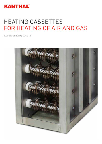
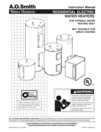
InstallationL.P. Gas Water HeaterThis section describes how to install the Water Heaterand control switch. Please consider the followingdirectives prior to beginning installation: This appliance must be installed by a qualifiedprofessional installer. The water heater tank must be supported at the samelevel as the bottom of the sidewall cutout. Provideadequate clearance at the rear of the unit for easyservice access to the water connections. If the appliance is installed where a connection ortank leakage can damage an adjacent area, install adrain pan (which can be drained outside of the RV)under the Water Heater. To install the Water Heater on carpeting, installthe Water Heater onto a metal or wood panel thatextends at least 3 in. (7.62 cm) beyond the total widthand depth of the Water Heater.ModelWH - 6GAWH - 6GEACutout Width andHeight12-7/8 in. 1/8 in.(32.70 cm 3.0 mm)WH - 9GEACutout Depth19.5 in.(49.53 cm)24.0 in.(60.96 cm)The following table shows the requirements for theminimum clearance from combustible construction.SidesBackTopBottom0 in.(0 cm)0 in.(0 cm))0 in.(0 cm)0 in.(0 cm)The following figure and table show the minimumrequired clearances between the water heater ventand any projection or plastic part on the side of theRV.4.1 Preparing the InstallationLocationtewyqr3 Vent Clearances2 Preparing the Installationq Water Heaterw Flangee Cutout Framer Cutout Widtht Cutout Heighty Cutout Depth1. Plan the location of the Water Heater within the RV.2. Erect the side walls and cut the square opening.Refer to the following tables for cutout and clearancespecifications for basic water heater models.6SidesTop3 in.(7.62 cm)12 in.(30.48 cm)3. Frame the cutout with 2 x 2 lumber or equivalent.4. Bend all flanges 90 along the scored lines.5. Block the Water Heater. Refer to “Blocking the WaterHeater” on page 7.EN
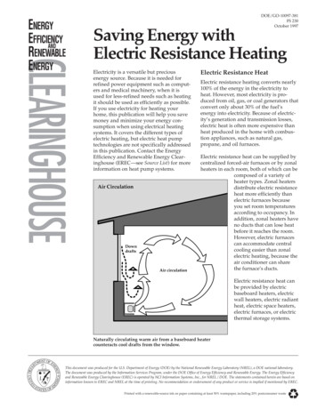
L.P. Gas Water HeaterInstallation4.2 Blocking the Water Heater4.3 Installing the Water Hosewqewerq4 Blocking the Water Heaterq Water Heaterw Cutout Framee Floorr Wood Block1. Place the Water Heater into the cutout location.2. At the back of the cutout, measure the distancebetween the side of the cutout and the side of theWater Heater.3. Remove the Water Heater from the cutout location.4. Mark the appropriate measured distance taken instep 2 on each side along the back of the cutout.5 Hose Connectionsq Water Heaterw Hot Water Outlete Cold Water Inlet5. Place a block of 2 x 2 lumber (minimum) that is at least6 in. (15 cm) long at each marked location.1. Position the Water Heater onto the planned locationon the floor of the RV.6. Secure the wood blocks to the floor.2. Remove the red thread protector from the 1/2 in.(1.27 cm) hot water outlet.3. Apply pipe lubricant to the threads of the1/2 in. (1.27 cm) National Pipe Tapered (NPT) hotwater outlet hose.4. Connect the 1/2 in. (1.27 cm) (NPT) hot water outlethose to the proper fitting on the Water Heater using asuitable fitting.NOTICE: Allow flexibility in the water and gas hoses soyou can pull the unit forward through the wall 1 in.(2.54 cm) past the skin.5. Remove the blue thread protector from the 1/2 in.(1.27 cm) cold water inlet.EN7
InstallationL.P. Gas Water Heater6. Apply sealant to the threads of the 1/2 in. (1.27 cm)(NPT) cold water inlet hose.4. Pull the 3/8 in. (0.95 cm) gas line and grommetthrough the opening in the water heater housing.7. Connect the 1/2 in. (1.27 cm) (NPT) cold water inlethose to the proper fitting on the Water Heater using asuitable plastic fitting.5. Connect the flare fitting and press the grommetinto the opening. Caulk around the grommet if thegrommet was cut during the gas line installation.4.4 Installing The Gas Line4.5 Installing The Control Switch(Rear)qeDometic recommends that the Water Heater unit beconnected directly to a 12 VDC battery or to the filteredside of an AC/DC converter. Avoid connections tothe unfiltered side of an AC/DC converter wheneverpossible. Use a minimum of 18-gauge wire, UL and CSAlisted.12 VDC control wiring in the Water Heater isIIThe18-gauge stranded wire rated for 105 C (221 F).This 18-gauge wire should be sufficient for the12 VDC control wire coming from the Water Heaterto the switch and the 12 VDC power source;however, consult all local and national codesrelating to your specific installation to verify.w(Front)4.5.1 Preparing the Control SwitchInstallation Locationw rq6 Sealing the Gas Line Opening With the Grommetq Water Heaterw Gas Linee Grommetr Housing Opening1. Connect the 3/8 in. (0.95 cm) flared L.P. gas line tothe Water Heater.2. Slide the grommet onto the 3/8 in. (0.95 cm) tubing.3. Flare the gas line as necessary.3/8 in. (0.95 cm) gas line is already flared, cutIIIfthethegrommeton one side. Place the split grommetover the gas line and press it into the opening in thehousing.8WARNING: FIRE AND OR ELECTRICAL SHOCKHAZARD. Failure to obey the followingwarnings could result in death or seriousinjury. Make sure there are no obstacles (wires, pipes,etc.) inside of the RV roof or walls at the installationlocations. Shut off the gas supply, disconnect the 120 VACpower from RV, and disconnect the positive ( ) 12VDC terminal from supply battery before drilling orcutting into the RV.illuminated light on the switch plate indicates aIIAnfault condition (no heat).When planning the location of the control switch(es), besure to choose an easily accessible area for both use andservice.single switch models will have twoIICombinationsingle switches (one for the gas heating elementand one for the electric control) that will need to beinstalled in convenient locations.EN
L.P. Gas Water HeaterInstallation4.5.2 Completing the Control SwitchInstallationto completing the control switch installation,IIPriorrefer to “Wiring the 115 VAC Power Supply” onqpage 9.ew1. Position the wall plate with the letters and symbolsoriented properly.2. Use four screws to mount the control switch. Tightenthe screws to hold the control switch(es) firmly inplace.3. Turn the switch(es) to the OFF position.dual control switches, ensure both switches areIIForturned to the OFF position.4.6 Wiring the 115 VAC PowerSupply7 Installing the Single Switchq Single Switchw Wall Mounting Screwqe Wall Cutoutew WARNING: FIRE HAZARD.When a cord and plug connection to the powersupply are used on a water heater, the power cordmust be UL listed as suitable for damp locations,hard or extra hard usage. The cord must be aflexible type such as S, SO, ST, STO, SJ, SJT, SJTO,HS or HSO described in the National ElectricCode ANSI/NFPA 70. The length of the externalcord to the water heater, measured to the faceof the attachment plug, shall be no less than 2 ft(60.96 cm) and no more than 6 ft (182.88 cm). Thesupply cord must be a minimum of 14 AWG. Theattachment plug must be rated at 15 A. Failure toobey this warning could result in death or seriousinjury.NOTICE: Do not route wires around sharp objects orwhere it could be smashed.8 Installing the Dual Switchq Dual Switchw Wall Mounting Screwe Wall Cutout1. Plan the location of the control switch(es).NOTICE: When using Romex with a bare earth ground,be sure to position the ground wire so it does notcontact the heating element terminals. Damage to theground wire can occur.to “Wiring Diagrams” on page 21 for aIIRefercomprehensive wiring schematic.2. Cut the appropriate size hole to fit the control switchleaving enough room to mount the switch using theproper hardware.EN9
InstallationL.P. Gas Water HeaterConsider the following before wiring the control switch: The three-prong plug must be secured to a ULapproved, dedicated, minimum 15 A-rated, threeprong receptacle. All wiring must comply with applicable electricalcodes. Use electrical metallic tubing, flexible metal conduit,metal clad cable, or nonmetallic-sheathed cable witha grounding conductor.3. Install the white wire or orange wire (depending onthe power source) from the Water Heater onto thespade connector on the back of the control switch.4. Install the green ground wire from the spadeconnector on the back of the control switch to anappropriate ground location.4.6.2 Configuring a Single CombinationControl Switch Wires must have a capacity of 1400 W or greater. The wiring method must conform to applicablesections of article 551 of National Electrical CodeANSI/NFPA 70. The receptacle must be located per all applicablecodes and away from any water.4.6.1 Configuring a Single Control Switchwqiueyr ti10 Single Combination Switch Wiringrqewq Heating Elementw Electronic Controle Lock-Out Lamp (Blue)r 12 VDC (Black)t Gas (Orange)y Electronic (White)u Ground (Green)i Jumper Wirecombination control models require the useIISingleof two switches. Assign and label one switch for thegas heating element and one switch for electroniccontrol.9 Control Switch Wiringq Lock-Out Lampe Controlw 12 VDC (Black)r Ground (Green)(Blue)(White/Orange)1. Install the blue wire for the lock-out lamp from theWater Heater onto the spade connector on the backof the control switch.2. Install the black 12 VDC wire onto the spadeconnector on the back of the control switch.101. Install the blue wire for the lock-out lamp from theWater Heater to the proper spade connector on theback of the control switch assigned for the heatingelement.2. Install the black 12 VDC wire to the spadeconnector on the back of the control switch assignedfor the gas heating element.3. Install the orange wire from the Water Heater ontothe spade connector on the back of the controlswitch assigned for the gas heating element.EN
L.P. Gas Water HeaterInstallation4. Install a jumper wire onto the spade connectors onthe back of each switch.5. Install another jumper wire onto the spadeconnectors on the back of each switch.6. Install the white wire from the Water Heater onto thespade connector on the back of the control switchassigned for electronic control.7. Install the green ground wire from the spadeconnector on the back of the control switch assignedfor electronic control and to an appropriate groundlocation.4.6.3 Configuring a Dual Control Switchtwiu4. Install the green ground wire from the Water Heaterto the negative post on the battery.5. Install the ground wire from the spade connector onthe blank port of the control switch to an appropriateground location.6. Install the jumper wire onto the spade connectorsbetween the electronic control switch and the gasheating element switch.7. Install the orange wire from the Water Heater ontothe spade connector on the gas heating elementswitch. qtq Control Switchw 12 VDC (Black)e Electronic (White)r Lock-Out Lamp (Blue)WARNING: CARBON MONOXIDE, FIRE AND/OR EXPLOSION HAZARD. Failure to obey thefollowing warnings could result in death orserious injury: Be sure the unit is vented and sealed properly toavoid the collection of carbon monoxide inside of theRV.e11 Dual Switch Wiringt Ground Wire (Green)y Gas (Orange)u Jumper Wirei BatteryIIThe face of the control switch indicates whichswitch is intended for each control option. Thelightning bolt indicates use with the electroniccontrol while the flame indicates use with the gasheating element. It is important to wire the switchesaccordingly.1. Install the black 12 VDC wire from the battery ontothe spade connector on the back of the electroniccontrol switch.EN3. Install the blue wire from the Water Heater for thelock-out lamp onto the spade connector on the blankport of the control switch.4.7 Installing The Unitry2. Install the white wire from the Water Heater to thespade connector on the back of the electroniccontrol switch. All combustion air must be supplied from outside ofthe RV. All combustion products must be vented tothe outside of the RV. Do not vent the water heater with a venting systemthat serves another appliance. Do not vent the water heater to an outside enclosedporch area. Protect building material from flue gas exhaust. Install the water heater on an exterior wall with accessto a door opening to the outdoors. Do not alter the water heater for a positive groundingsystem. Do not high-potential test (HI-POT) the water heaterunless the DSI control board has been disconnected(DC HI-POT).11
InstallationL.P. Gas Water Heater Do not use a battery charger to supply power to thewater heater at any time or when testing.qNOTICE: Do not modify the water heater in any way.NOTICE: Do not lift, push, or misalign the main burnertube. Damage to the burner and the water heater canoccur.in recreation vehicles only. RVs are recreationIIInstallvehicles designed for temporary living quartersfor recreation, camping, or travel using their ownpower or towed by another vehicle.rwqewt13 Securing the Brackets to the Water Heater Flangeq Top Corner Bracketsr Bottom Left CornerBracketw Left Hinge Brackett Bottom Right Cornere #8 3/4 in. Round Head BracketScrews (qty. 18)12 Caulking the Unitq Openingw Flange Slots1. Caulk throughly around the opening and the flangeslots.tape 1-1/4 in. x 1/8 in. (32 mm x 3 mm) mayIIButylbe substituted for caulking material.2. Push the unit against the caulking in the cutout.3. Secure the two top corner brackets to the waterheater flange using six #8 3/4 in. round head screwsor equivalent.IIThe screws are not provided with the unit.4. Place the left hinge bracket over the bottom leftcorner bracket and secure them to the housing usingthree #8 3/4 in. round head screws or equivalent.5. For the bottom right corner bracket, attach using onlyone #8 3/4 in. round head screw or equivalent in thetop hole for now.6. Secure the housing to the RV using eight #8 3/4 in.round head screws or equivalent in the holes aroundthe flange.7. Visually inspect all gaskets to ensure that they adhereto the pan and create an air tight seal.12EN
L.P. Gas Water HeaterOperation4.8 Installing The Access Door4.9 Performing Leak Testing wWARNING: FIRE AND/OR EXPLOSIONHAZARD.Do not use matches, candles, or other sourcesof control when checking for gas leaks. Failure toobey this warning could result in death or seriousinjury.the Water Heater from the gas supply pipingIIIsolatesystem before performing any pressure test equal toqor greater than 0.5 PSI (34 mbar).1. Turn on the gas and check the Water Heater and allof the connections for gas leaks using leak detectionsolution.2. Fill the water heater tank with water.14 Sliding the Access Door onto the Left Hinge Bracketq Left Hinge Bracketw Access Door1. Slide the access door onto the left hinge bracket.3. Check the tank and all water hose connections for leaks.5 Operation q we15 Attaching the Right Hinge Bracketq Right Hinge Bracketw Access Doore #8 3/4 in. Round HeadScrews (qty. 2)2. Slide the right hinge bracket into the access door,and place against the right corner bracket. Secure theright hinge bracket using two #8 3/4 in. screws.3. Seal both corners with caulk.ENWARNING: BURN HAZARD, FIRE,EXPLOSION, AND/OR CARBON MONOXIDEHAZARD.Keep the water heater area clear of combustiblecleaning materials, gasoline, and other flammablevapors and liquids. Failure to obey this warningcould result in death or serious injury.WARNING: FIRE AND/OR EXPLOSIONHAZARD. Failure to obey this warning couldresult in death or serious injury: Do not store or use gasoline or other flammablevapors and liquids in the vicinity of this or any otherappliance. Should overheating occur, or the gas supply fail toshut off, turn the operating switch to the OFF positionand remove the red wire from the left hand terminal ofthe E.C.O. switch or turn the gas off at the L.P. tank. Use with L.P. gas only. Shut off gas appliances and pilot lights whenrefueling. Turn gas off at the L.P. tank when the vehicle is inmotion. This disables all gas appliances and pilotlights.13
Operation Gas appliances must never be operated while thevehicle is in motion. Unpredictable wind currentsmay be created which could cause flame reversal inthe burner tub, which could result in fire damage.The thermal cut off fuse could also be unnecessarilyactivated resulting in a complete shutdown of thewater heater requiring replacement of the thermalcut off. CAUTION: FIRE HAZARD.Do not smoke or have any flame near an openfaucet. Failure to obey this caution could result inminor or moderate injury.CAUTION: EXPLOSION HAZARD.If water heater has not been used for more than twoweeks, hydrogen gas may form in the water line.Under these conditions, to reduce the risk of injury,open the hot water faucet for several minutes at thekitchen sink before you use any electrical applianceconnected to hot water system. If hydrogen gasis present, you will probably hear sounds like airescaping through the pipe as water begins to flow.Failure to obey this warning could result in death orserious injury.NOTICE: Do not operate without water in tank, productfailure can occur.5.1 Operating the Electronic ControlL.P. Gas Water Heater5.1.1 Gas Function WARNING: BURN HAZARD, FIRE,EXPLOSION, AND/OR CARBON MONOXIDEHAZARD.Keep the water heater area clear of combustiblecleaning materials, gasoline, and other flammablevapors and liquids. Failure to obey this warningcould result in death or serious injury.When the gas heating element switch is turned tothe ON position, the Water Heater will make threeattempts to light. If for any reason there is no ignition,the Water Heater will lockout and the red lockout lampwill illuminate. If the thermostat fails, the E.C.O. will alsolockout the Water Heater and a reset will be required.Determine the reason for no control, correct it, and resetthe gas control sequence by turning the switch to theOFF position then to the ON position.5.1.2 Electric Heating ElementWhen the electric element switch is turned to the ONposition, the relay will close and pass 110 VAC to theelement. If the thermostat fails, the E.C.O. will open andlockout the system. To correct, check the thermostat toassure good contact with the tank. Reset the control by
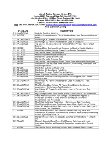
L .P . Gas Water Heater Installation 3.4 Unit Specifications The Basic Water Heater Specifications Table provides the unit dimensions and weight specifications for basic 6-gallon water heater models. Basic Water Heater Specifications Table Width Height Shipping Weight 12.75 in. (32.38 cm) 12.75 in. (32.38 cm) 25 lbs (11.33 Kg)