Transcription
13 Automated Production Lines13.113.213.313.413.513.613.713.8Unit IntroductionUnit Learning ObjectivesFundamentals of Automated Production LinesApplications of Automated Production LinesAnalysis of Transfer LinesUnit ReviewSelf Assessment QuestionsSelf Assessment Answers13.1 IntroductionAutomated production lines are typically used for high production of parts thatrequire multiple processing operations. The production line itself consists ofgeographically dispersed workstations within the plant, which are connected by amechanized work transport system that ferries parts from one workstation toanother in a pre-defined production sequence. In cases where machiningoperations, such as drilling, milling, and similar rotating cutter processes, areperformed at particular workstations, the more accurate term to use is transferline, or transfer machine. Other potential automated production line applicationsinclude: robotic spot-welding, sheet-metal press-working, and electroplating ofmetals.KEYPOINTAutomated production lines consist of distributed workstations connected by amechanized work transport system that moves the parts from one workstation toanother as they enter the system.END KEYPOINTAutomated production lines are usually expensive to implement, and—asexamples of fixed automation—their layout is relatively hard to change once builtinto the production plant’s infrastructure. The following are the conditions thatnormally suit the used of automated production lines:BULLETLISTHigh product demand, requiring high production quantitiesStable product design, as automated production lines cannot accommodatefrequent design changesLong product life—typically several yearsMultiple operations, involving the use of a number of workstationsENDLIST
KEYPOINTThe conditions that determine the use of automated production lines include:high product demand; stable product design; long product life; and multipleoperations.END KEYPOINTOnce these conditions are met, the following benefits are usually seen to accruefrom using automated production lines:NUMLISTLow amount of direct labourLow product costHigh production rateMinimal work-in-progress and production lead timeMinimal use of factory floor spaceENDLISTIn this unit a general overview of automated production lines is offered, whichexamines the fundamentals of automated lines (i.e. system configuration,workpart transfer mechanisms, storage buffers, and control of the productionline), as well as the applications of production lines for machining systems andsystem design considerations. This is followed by an analysis of transfer lines,both with no internal parts storage, and with internal storage buffers.13.2 Learning ObjectivesAfter completing this unit, and the assigned reading and exercises supplied, youshould be able to:BULLET LISTDefine the concept of automated production linesSpecify the components of automated productionOutline the system configurations used in automated productionExplain the types of transfer mechanism that may be used for workpart transferDescribe the Geneva mechanismOutline how storage buffers may be deployed in automated production lines
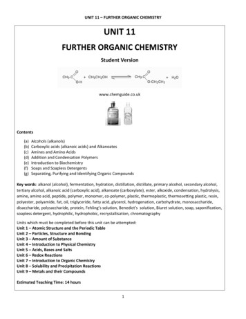
List the basic control functions that can be distinguished in the operation of anautomatic transfer machineExplain the concept of a transfer lineOutline the approaches that may be used for system designList the three areas that can be considered for analysis in connection withtransfer linesSpecify common metrics used to assess transfer lines with no internal partsstorageExplain how storage buffers affect transfer line downtimeSpecify the factors involved in considering the overall line efficiency for a twostage transfer lineENDLIST13.3 Fundamentals of Automated Production LinesAn automated production line has multiple workstations that are automated andlinked together by a work handling system that transfers parts from one station tothe next, as in Figure 13.1. Starting—un-processed—parts enter the automatedproduction line and undergo a system of automated processing at variousworkstations along the fixed production line; the parts are passed fromworkstation to workstation by means of a mechanized work transport system,until the completely processed parts pass out of the automated production lineafter the last process occurs to the part at the final workstation in the system.Figure 13.1: General configuration of an automated production lineKEYPOINTIn automated production un-processed parts enter the production line andundergo a system of automated processing at various workstations along thefixed production line, with parts being moved from one workstation to the next bymeans of a mechanized work transport system, until the last process occurs to
the part at the final workstation in the system, at which point the part exits theautomated production line.END KEYPOINTThe line may also include inspection stations to perform intermediate qualitychecks on parts in the system, as well as a number of manually-operatedworkstations that accomplish tasks that have not been automated owing toreasons of economy or difficulty. Each station performs a different operation, soall the operations are required to complete one work unit; this means that theparts’ route through the production line is fixed and cannot be changed. Multipleparts are processed simultaneously, with one part undergoing processing at eachworkstation in the system. This means, in the simplest automated productionlines, that the number of parts in the system is found to be equal to the number ofworkstations that the system has; however, in more complicated configurations,provision may have been made for some form of part storage, so this calculationmay not be accurate where buffering is manifest.KEYPOINTThe automated production may consist of, besides automated workstations,manual workstations and inspection stations.END KEYPOINTThe automated production line operates in cycles with the slowest workstationprocessing time setting the pace for the whole line. Each cycle consists of theprocessing time plus the time taken to transfer parts from one workstation to thenext.Certain layouts of transfer lines may allow the use of pallet fixtures for parthandling (see Unit 8), the description of which has seen the emergence of theterm palletized transfer lines to describe these. The alternative method ofworkpart location is simply to index the parts themselves from station to station;this is described as a free transfer line, and is less expensive than the palletizedtransfer line as pallet fixtures do not have to be custom-designed for the worktransport system. However, certain workpart geometries mandate the use ofpallets and pallet fixtures, in which case a system of returning them to the front ofthe line must be devised.KEYPOINTFor transfer line layouts either palletized transfer lines (that use pallets and palletfixtures) or free transfer lines (that use no special fixtures or workpart holders)may be favoured.END KEYPOINT13.3.1 System Configurations
A number of system configurations for the automated production line exist; theseare detailed in Table 13.1.Table 13.1: System configurations for the automated production lineConfigurationIn-lineSegmented in-line:L-shaped layoutU-shaped layoutDescriptionConsists of asequence ofworkstations in astraight-linearrangement.Common formachining big workpieces, such asautomotive engineblocks, engineheads, andtransmission cases.Can accommodatea large number ofworkstations, andbuffer storage canalso be planned forthe configuration.Consists of two ormore straight-linetransfer sections,where thesegments areusuallyperpendicular toeach other. Layoutdesigns include theL-shaped layout,the U-shapedlayout, and theRectangular layout.Reasons forfavouringsegmented in-lineover in-lineconfigurationsinclude: floor spaceconsiderations; reorientation ofworkparts topresent differentsurfaces formachining indifferent linesegments; the swiftreturn of workholding fixtures (inthe rectangulararrangement).
Rectangular layoutRotaryConsists of acircular worktablearound whichworkparts are fixedto workholders. Theworktable rotates tomove eachworkpart, in turn,into eachautomatedworkstation whichis located aroundthe circumferenceof the worktable.The worktable isoften called a dial,and the equipmentis referred to as adial indexingmachine, or simply,indexing machine.Commonly limitedto smallerworkparts andrelatively fewworkstations, andthey cannot readilyaccommodatebuffer storagecapacity. Howeverthey require lessfloor space, andare generally lessexpensive thanotherconfigurations.KEYPOINTA number of system configurations for the automated production line exist; theseinclude: in-line configurations; segmented in-line configurations (for example, Lshaped layouts, U-shaped layouts, and Rectangular layouts); and rotaryconfigurations.END KEYPOINT
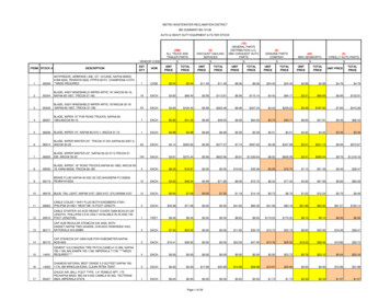
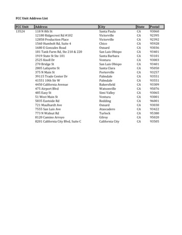
Sometimes a mix of the above configurations may be favoured in particularcases. For example in Figure 13.2; here is illustrated two transfer lines thatperform metal machining operations on a rear truck axle. The first line consists ofa segmented in-line configuration, in the rectangular layout; the second line is inthe conventional in-line configuration. There also exists a number of bufferstorage locations within the configuration, particularly from one transfer line to thenext.Figure 13.2: Two machining transfer linesKEYPOINTA mix of the automated production line configurations may be favoured in certainmanufacturing environments.END KEYPOINT13.3.2 Workpart Transfer MechanismsThe function of the workpart transfer system is to move parts between stationson the production line, a function performed by means of transfer mechanismsthat are either synchronous or asynchronous. Synchronous transfer is thetraditional method of moving parts within a production system, but asynchronoustransfer has the following advantages:BULLETLISTGreater flexibility
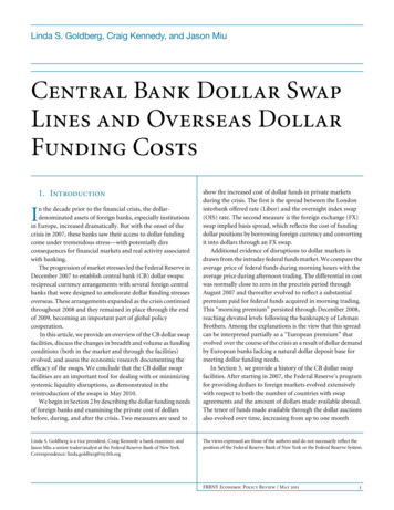
Fewer pallet fixtures neededEasy to rearrange or expand the production systemENDLISTThese advantages must be offset by a higher first cost, and the fact thatasynchronous transfer is hard to regulate accurately as moving parts passbetween station workheads.KEYPOINTTransfer mechanisms in the workpart transfer system may be synchronous orasynchronous.END KEYPOINTHere we examine two types of workpart transfer mechanism: linear transportsystems for in-line systems (with synchronous and asynchronous transfer); androtary indexing mechanisms for dial indexing machines (with synchronoustransfer only).13.3.2.1 Linear Transfer SystemsTypes of linear transfer systems used for workpart transfer include powered rollerconveyors, belt conveyors, chain driven conveyors, and cart-on-track conveyorspreviously described in unit 8. The typical installation of a conveyor system forworkpart transfer is depicted in Figure 13.3. Work carriers attached to theconveyor ensure that workparts are transferred in a synchronous fashion fromone workstation to the next, while the ‘over-and-under’ design of the conveyorbelt ensures a continuous supply of empty carriers for reloading. The beltconveyor can also be used for asynchronous transfer of parts by using frictionbetween the belt and the part to move parts between stations. Parts are stoppedin their forward motion by means of pop-up pins, or other stopping mechanisms.Figure 13.3: Side view of chain or belt conveyor deploying work carriers, used forlinear workpart transfer
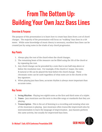
Cart-on-track conveyors provide asynchronous movement of parts, and aredesigned to position their carts within about 0.12mm, which is adequate formany processing operations. Other mechanisms for locating carts may also beused, such as pin-in-hole devices and detente devices.Linear transfer lines also come in the form of walking beam transfer systems,where parts are moved synchronously by means of a transfer beam that liftsparts from their respective stations and transfers them one position ahead. Partsare lowered into specially-designed ‘nests’ that position them for processing atthe next station, then the transfer beam retracts to make ready for the nexttransfer cycle. This action sequence is illustrated in Figure 13.4.Figure 13.4: Operation of the walking beam systemKEYPOINTLinear transfer systems used for workpart transfer include powered rollerconveyors, belt conveyors, chain driven conveyors, and cart-on-track conveyors,as well as the walking beam transfer system.END KEYPOINT13.3.2.2 Rotary Indexing MechanismsSeveral mechanisms can be used to generate the type of rotary power requiredby rotary indexing machines. Two of these are the Geneva mechanism, and thecam drive.The Geneva mechanism (see Figure 13.5) uses a continuously rotating driver toindex the table through a partial rotation.
Figure 13.5: Six-slotted Geneva mechanismIf the driven member has six slots for a six station dial indexing table, each turnof the driver results in a 1/6th rotation of the worktable, or 60o. The driver onlycauses motion of the table through a portion of its own rotation. The operation ofthe mechanism may be shown by reference to Figure 13.6, which shows therotation of Geneva mechanism with four slots.Figure 13.6: The operation of a four-slot Geneva mechanismFor a six-slotted Geneva, which we focus upon here, 120 o of driver rotation isused to index the table, with the remaining 240 o being dwell time for the table,during which the processing operation must be completed on the work unit. Ingeneral: 360nswhere Θ is the angle of rotation of the worktable during indexing (degrees ofrotation); and ns is the number of slots in the Geneva. The angle of driver rotationduring indexing is 2 Θ, and the angle of driver rotation during the dwell time isgiven by:360 2
The number of slots of the Geneva mechanism determines the number ofworkstation positions around the periphery of the rotary index machine. Genevamechanisms with four, five, six, or eight slots are common. Given the rotationalspeed of the
A number of system configurations for the automated production line exist; these are detailed in Table 13.1. Table 13.1: System configurations for the automated production line Configuration Description In-line Consists of a sequence of workstations in a straight-line arrangement. Common for machining big work pieces, such as automotive engine