Transcription
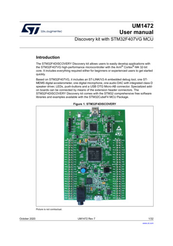
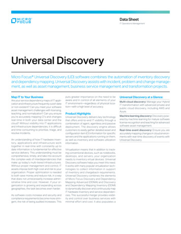
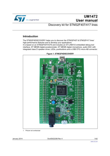
UM1472User manualDiscovery kit for STM32F407/417 linesIntroductionThe STM32F4DISCOVERY helps you to discover the STM32F407 & STM32F417 lines’high-performance features and to develop your applications.It is based on an STM32F407VGT6 and includes an ST-LINK/V2 embedded debug toolinterface, ST MEMS digital accelerometer, ST MEMS digital microphone, audio DAC withintegrated class D speaker driver, LEDs, pushbuttons and a USB OTG micro-AB connector.Figure 1. STM32F4DISCOVERY1. Picture not contractualJanuary 2014DocID022256 Rev 41/42www.st.com
ContentsUM1472Contents1Conventions . . . . . . . . . . . . . . . . . . . . . . . . . . . . . . . . . . . . . . . . . . . . . . . . 52Quick start . . . . . . . . . . . . . . . . . . . . . . . . . . . . . . . . . . . . . . . . . . . . . . . . . 62.1Getting started . . . . . . . . . . . . . . . . . . . . . . . . . . . . . . . . . . . . . . . . . . . . . . 62.2System requirements . . . . . . . . . . . . . . . . . . . . . . . . . . . . . . . . . . . . . . . . . 62.3Development toolchain supporting the STM32F4DISCOVERY . . . . . . . . . 62.4Order code . . . . . . . . . . . . . . . . . . . . . . . . . . . . . . . . . . . . . . . . . . . . . . . . . 63Features . . . . . . . . . . . . . . . . . . . . . . . . . . . . . . . . . . . . . . . . . . . . . . . . . . . 74Hardware and layout . . . . . . . . . . . . . . . . . . . . . . . . . . . . . . . . . . . . . . . . . 84.1STM32F407VGT6 microcontroller . . . . . . . . . . . . . . . . . . . . . . . . . . . . . . 114.2Embedded ST-LINK/V2 . . . . . . . . . . . . . . . . . . . . . . . . . . . . . . . . . . . . . . 134.2.1Using ST-LINK/V2 to program/debug the STM32F4 on board . . . . . . . 144.2.2Using ST-LINK/V2 to program/debug an external STM32 application . . 154.3Power supply and power selection . . . . . . . . . . . . . . . . . . . . . . . . . . . . . . 164.4LEDs . . . . . . . . . . . . . . . . . . . . . . . . . . . . . . . . . . . . . . . . . . . . . . . . . . . . . 164.5Pushbuttons . . . . . . . . . . . . . . . . . . . . . . . . . . . . . . . . . . . . . . . . . . . . . . . 164.6On board audio capability . . . . . . . . . . . . . . . . . . . . . . . . . . . . . . . . . . . . . 174.7USB OTG supported . . . . . . . . . . . . . . . . . . . . . . . . . . . . . . . . . . . . . . . . 174.8Motion sensor (ST MEMS LIS302DL or LIS3DSH) . . . . . . . . . . . . . . . . . 174.9JP1 (Idd) . . . . . . . . . . . . . . . . . . . . . . . . . . . . . . . . . . . . . . . . . . . . . . . . . . 184.10OSC clock . . . . . . . . . . . . . . . . . . . . . . . . . . . . . . . . . . . . . . . . . . . . . . . . 194.10.1OSC clock supply . . . . . . . . . . . . . . . . . . . . . . . . . . . . . . . . . . . . . . . . . 194.10.2OSC 32 KHz clock supply . . . . . . . . . . . . . . . . . . . . . . . . . . . . . . . . . . . 194.11Solder bridges . . . . . . . . . . . . . . . . . . . . . . . . . . . . . . . . . . . . . . . . . . . . . 204.12Extension connectors . . . . . . . . . . . . . . . . . . . . . . . . . . . . . . . . . . . . . . . . 215Mechanical drawing . . . . . . . . . . . . . . . . . . . . . . . . . . . . . . . . . . . . . . . . 346Electrical schematics . . . . . . . . . . . . . . . . . . . . . . . . . . . . . . . . . . . . . . . 357Revision history . . . . . . . . . . . . . . . . . . . . . . . . . . . . . . . . . . . . . . . . . . . 412/42DocID022256 Rev 4
UM1472List of tablesList of tablesTable 1.Table 2.Table 3.Table 4.Table 5.Table 6.ON/OFF conventions . . . . . . . . . . . . . . . . . . . . . . . . . . . . . . . . . . . . . . . . . . . . . . . . . . . . . . 5Jumper states . . . . . . . . . . . . . . . . . . . . . . . . . . . . . . . . . . . . . . . . . . . . . . . . . . . . . . . . . . . 13Debug connector CN2 (SWD). . . . . . . . . . . . . . . . . . . . . . . . . . . . . . . . . . . . . . . . . . . . . . . 15Solder bridges. . . . . . . . . . . . . . . . . . . . . . . . . . . . . . . . . . . . . . . . . . . . . . . . . . . . . . . . . . . 20MCU pin description versus board function . . . . . . . . . . . . . . . . . . . . . . . . . . . . . . . . . . . . 21Document revision history. . . . . . . . . . . . . . . . . . . . . . . . . . . . . . . . . . . . . . . . . . . . . . . . . . 41DocID022256 Rev 43/423
List of figuresUM1472List of figuresFigure 1.Figure 2.Figure 3.Figure 4.Figure 5.Figure 6.Figure 7.Figure 8.Figure 9.Figure 10.Figure 11.Figure 12.Figure 13.Figure 14.Figure 15.Figure 16.4/42STM32F4DISCOVERY . . . . . . . . . . . . . . . . . . . . . . . . . . . . . . . . . . . . . . . . . . . . . . . . . . . . . 1Hardware block diagram . . . . . . . . . . . . . . . . . . . . . . . . . . . . . . . . . . . . . . . . . . . . . . . . . . . 8Top layout . . . . . . . . . . . . . . . . . . . . . . . . . . . . . . . . . . . . . . . . . . . . . . . . . . . . . . . . . . . . . . 9Bottom layout . . . . . . . . . . . . . . . . . . . . . . . . . . . . . . . . . . . . . . . . . . . . . . . . . . . . . . . . . . . 10STM32F407VGT6 package . . . . . . . . . . . . . . . . . . . . . . . . . . . . . . . . . . . . . . . . . . . . . . . . 11STM32F407VGT6 block diagram . . . . . . . . . . . . . . . . . . . . . . . . . . . . . . . . . . . . . . . . . . . 12Typical configuration . . . . . . . . . . . . . . . . . . . . . . . . . . . . . . . . . . . . . . . . . . . . . . . . . . . . . 13STM32F4DISCOVERY connections image . . . . . . . . . . . . . . . . . . . . . . . . . . . . . . . . . . . . 14ST-Link connections image. . . . . . . . . . . . . . . . . . . . . . . . . . . . . . . . . . . . . . . . . . . . . . . . . 15STM32F4DISCOVERY mechanical drawing . . . . . . . . . . . . . . . . . . . . . . . . . . . . . . . . . . . 34STM32F4DISCOVERY . . . . . . . . . . . . . . . . . . . . . . . . . . . . . . . . . . . . . . . . . . . . . . . . . . . . 35ST-LINK/V2 (SWD only) . . . . . . . . . . . . . . . . . . . . . . . . . . . . . . . . . . . . . . . . . . . . . . . . . . . 36MCU . . . . . . . . . . . . . . . . . . . . . . . . . . . . . . . . . . . . . . . . . . . . . . . . . . . . . . . . . . . . . . . . . . 37Audio. . . . . . . . . . . . . . . . . . . . . . . . . . . . . . . . . . . . . . . . . . . . . . . . . . . . . . . . . . . . . . . . . . 38USB OTG FS . . . . . . . . . . . . . . . . . . . . . . . . . . . . . . . . . . . . . . . . . . . . . . . . . . . . . . . . . . 39Peripherals . . . . . . . . . . . . . . . . . . . . . . . . . . . . . . . . . . . . . . . . . . . . . . . . . . . . . . . . . . . . . 40DocID022256 Rev 4
UM14721ConventionsConventionsTable 1 provides the definition of some conventions used in the present document.Table 1. ON/OFF conventionsConventionDefinitionJumper JP1 ONJumper fittedJumper JP1 OFFJumper not fittedSolder bridge SBx ONSBx connections closed by solderSolder bridge SBx OFF SBx connections left openDocID022256 Rev 45/4241
Quick start2UM1472Quick startThe STM32F4DISCOVERY is a low-cost and easy-to-use development kit to quicklyevaluate and start a development with an STM32F4 high-performance microcontroller.Before installing and using the product, please accept the Evaluation Product LicenseAgreement from www.st.com/stm32f4-discovery.For more information on the STM32F4DISCOVERY and for demonstration software, visitwww.st.com/stm32f4-discovery.2.1Getting startedFollow the sequence below to configure the STM32F4DISCOVERY board and launch theDISCOVER application:1. Check jumper position on the board, JP1 on, CN3 on (DISCOVERY selected).2. Connect the STM32F4DISCOVERY board to a PC with a USB cable ‘type A to mini-B’through USB connector CN1 to power the board. Red LED LD2 (PWR) then lights up.3. Four LEDs between B1 and B2 buttons are blinking.4. Press user button B1 to enable the ST MEMS sensor, move the board and observe thefour LEDs blinking according to the motion direction and speed. (If you connect asecond USB cable ‘type A to micro-B’ between PC and CN5 connector then the boardis recognized as standard mouse and its motion will also control the PC cursor).5. To study or modify the DISCOVER project related to this demo, visitwww.st.com/stm32f4-discovery and follow the tutorial.6. Discover the STM32F4 features, download and execute programs proposed in the listof projects.7. Develop your own application using available examples.2.2System requirements 2.3Development toolchain supporting the STM32F4DISCOVERY 2.4Windows PC (XP, Vista, 7)USB type A to Mini-B USB cableAltium, TASKING VX-ToolsetAtollic TrueSTUDIO IAR Embedded Workbench for ARM (EWARM)Keil , MDK-ARMOrder codeTo order the STM32F4 high-performance discovery board, use the order codeSTM32F4DISCOVERY.6/42DocID022256 Rev 4
UM14723FeaturesFeaturesThe STM32F4DISCOVERY offers the following features: STM32F407VGT6 microcontroller featuring 1 MB of Flash memory, 192 KB of RAM inan LQFP100 package On-board ST-LINK/V2 with selection mode switch to use the kit as a standaloneST-LINK/V2 (with SWD connector for programming and debugging) Board power supply: through USB bus or from an external 5V supply voltage External application power supply: 3V and 5V LIS302DL or LIS3DSH, ST MEMS motion sensor, 3-axis digital output accelerometer MP45DT02, ST MEMS audio sensor, omnidirectional digital microphone CS43L22, audio DAC with integrated class D speaker driver Eight LEDs:–LD1 (red/green) for USB communication–LD2 (red) for 3.3V power on–Four user LEDs, LD3 (orange), LD4 (green), LD5 (red) and LD6 (blue)–2 USB OTG LEDs LD7 (green) VBus and LD8 (red) over-current Two pushbuttons (user and reset) USB OTG with micro-AB connector Extension header for LQFP100 I/Os for quick connection to prototyping board and easyprobingDocID022256 Rev 47/4241
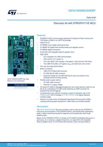
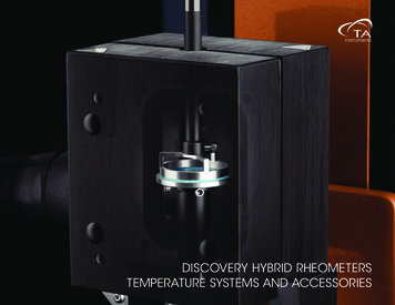
Hardware and layout4UM1472Hardware and layoutThe STM32F4DISCOVERY is designed around the STM32F407VGT6 microcontroller in a100-pin LQFP package.Figure 2 illustrates the connections between the STM32F407VGT6 and its peripherals (STLINK/V2, pushbutton, LED, Audio DAC, USB, ST MEMS accelerometer, ST MEMSmicrophone, and connectors).Figure 3 and Figure 4 help you to locate these features on the STM32F4DISCOVERY.Figure 2. Hardware block diagram0LQL86%6:'(PEHGGHG67 /,1. 9 670 ) 9*7 , 25(6(7/('/' WR /' % 56703 '7 % 86(5&6 / 0LQL -DFN HDGHU, 2 HDGHU, 2/,6 '/ RU/,6 '6 0LFUR 86%06 9 8/42DocID022256 Rev 4
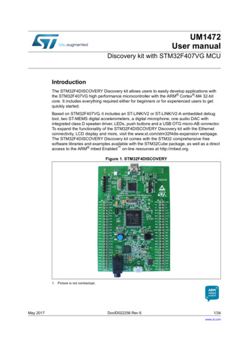
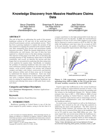
UM1472Hardware and layoutFigure 3. Top layout67 /,1. 9 /' UHG JUHHQ /(' &20&1 6:' FRQQHFWRU/' UHG /('3:55 ' &1 /' 5 5 5 5 5 5 & & &20' &1 & 8 & 5 & 67 /,1.8 & 5 & 5 ' &1 5 5 &',6&29(5 5& 5 & 5 5 6:'; & 5 3:5/' 5 5 & & & & & & & 5 5 9''*1'15673& 3& 3& 3& 3 3 3 3 3 3 3 3 & ; 5 & & & / & 5 5 8 5 & & & & & 5 9''3 ; 5 *1'& *1'& 8 5 & ZZZ VW FRP VWP I GLVFRYHU\3 -3 5 ,GG5 670 ) 9*7 5 5 5 *1'*1' 9 9 9 93 3 3& 3& 3( 3& 3( 3( 3( 3( 3( 3( & & 5 % 8 /' % 3% 3% 3% 3% 3% 3' 3'3' 3' 3' &1 & 3' 3' 3' 1&5 5 5 8 & 5 8 5HVHW5 5 & & 5 & 5 3% 5 5 & & 5 & & & 5 8 5 5 5 & 5 5 & 5 3%9''3% 3% 3% 3% 3' 3% 3' 3' 3' 3' 3' 3' 3& 3' 3& 3& 3 3 3 3 3 3 3& 3&3& 5 /' & 83& *1'*1'/' *1' 9 SRZHUVXSSO\ RXWSXW 6% % 5(6(7/' RUDQJH /('/' UHG /(' % UHVHW EXWWRQ 7 &1 5 3% %227 9 SRZHUVXSSO\ LQSXW RXWSXW& 5 3( 3( /' 5 3( 8VHU5 3( & 3( & & 3( 5 & 3(/' 5 JUHHQ /(' /' & /' 5 5 3( 5 & 5 5 3% 5 & *1'3( 6% & & 3% & EOXH /(' /' 3& 3% & JUHHQ /(' /' 3& & % XVHU EXWWRQ&1 67 /,1. ',6&29(5 VHOHFWRU5 & -3 ,'' PHDVXUHPHQW 0% &*1'5 /' UHG /(' 06 9 Note:Pin 1 of CN2, CN3, JP1, P1 and P2 connectors are identified by a square.DocID022256 Rev 49/4241
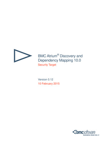
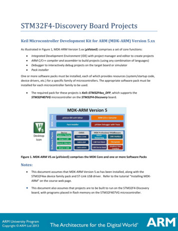
Hardware and layoutUM1472Figure 4. Bottom layout3" 3" 3" 3" 2%3%26% 3" .2343" 3" 3" 3" %&!5,43" 34-?2343" 8 CRYSTAL3" 8 CRYSTAL3" 37/3" 8 CRYSTAL3" 8 CRYSTAL3" 6 FROM 63" "//4 3" "//4 3" " 53%2-3 6 10/42DocID022256 Rev 4
UM14724.1Hardware and layoutSTM32F407VGT6 microcontrollerThis ARM Cortex-M4 32-bit MCU with FPU has 210 DMIPS, up to 1 MB Flash/192 4 KBRAM, USB OTG HS/FS, Ethernet, 17 TIMs, 3 ADCs, 15 comm. interfaces and a camera.Figure 5. STM32F407VGT6 package34- & 6'4 -BYTE OF &LASH MEMORY BYTES OF 2!-,1&0 X MM-3 6 This device provides the following benefits. 168 MHz/210 DMIPS Cortex-M4 with single cycle DSP MAC and floating point unitproviding:Boosted execution of control algorithmsMore features possible for your applicationsEase of useBetter code efficiencyFaster time to marketElimination of scaling and saturationEasier support for meta-language tools Designed for high performance and ultra fast data transfers; ART Accelerator, 32-bit, 7layer AHB bus matrix with 7 masters and 8 slaves including 2 blocks of SRAM, MultiDMA controllers: 2 general purpose, 1 for USB HS, 1 for Ethernet, One SRAM blockdedicated to the core, providing performance equivalent to 0-wait execution from FlashConcurrent execution and data transfers and simplified resource allocation Outstanding power efficiency; Ultra-low dynamic power, RTC 1 μA typical in VBATmode, 3.6 V down to 1.7 V VDD, Voltage regulator with power scaling capability,providing extra flexibility to reduce power consumption for applications requiring bothhigh processing and low power performance when running at low voltage or on arechargeable battery Maximum integration: Up to 1 Mbyte of on-chip Flash memory, 192 Kbytes of SRAM,reset circuit, internal RCs, PLLs, WLCSP package available, providing more features inspace constrained applications Superior and innovative peripherals providing new possibilities to connect andcommunicate high speed data and more precision due to high resolution Extensive tools and software solutions providing a wide choice within the STM32ecosystem to develop your applications.DocID022256 Rev 411/4241
Hardware and layoutUM1472Figure 6. STM32F407VGT6 block diagram%XTERNAL MEMORYCONTROLLER &3-###- DATA 2!- "*4!' 37-05.6)#%4- "5353"/4' (3 3TREAMS -! 32!- "32!- "!(" -(Z&)&/!((" -(Z 3TREAMS -! 2.'6 6 !0!; 0";
www.st.com/stm32f4-discovery. 2.1 Getting started Follow the sequence below to configure the STM32F4DISCOVERY board and launch the DISCOVER application: 1. Check jumper position on the board, JP1 on, CN3 on (DISCOVERY selected). 2. Connect the STM32F4DISCOVERY board to a PC with a USB cable ‘type A to mini-B’