Transcription
Straight Line Reference System (SLRS)for the adjustment of the X-ray free-electronLaser (XFEL) @ DESYDaniel Kaemtner, Johannes PrentingDESYApplied Geodesy GroupIWAA 2006SLAC, Menlo Park, California, September 2006
Straight Line Reference System (SLRS)for the adjustment of the X-ray free-electronLaser (XFEL) @ DESYOutline of presentation:1. Overview about new projects at DESY2. SLRS-XFEL3. Poisson Alignment System:- Introduction- Simulation- Empirical tests4. Direct light source System:- Introduction- Empirical tests5. SummaryApplied Geodesy Group6. Future developmentsIWAA 2006SLAC, Menlo Park, California, September 2006
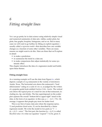
SLRS for XFEL @ DESYnew projectsNEW PROJECTSSLRS @ XFELXFEL (planned)POISSONALIGNMENTSYSTEMDORISFLASHDIRECT LIGHTSOURCEPETRA III lash : world record: 13.5nm with 10 mW, rep. rate 150x / secondPETRA III : conversion into one of the most brilliant x-ray sources worldwideXFEL : approved statement „Planfeststellungsbeschluß“ publishedJ. Prenting, D. KaemtnerGeodesy @ DESYSeptember 2006
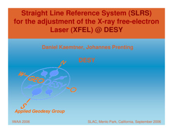
SLRS for XFEL @ DESYNEW PROJECTSSLRS @ XFELA light source of superlatives:The European X-Ray LaserProject: XFELThe extremely intensive and ultrashortX-ray laser flashes will enable scientiststo "film" with atomic resolutionthe behaviour of, for example,materials or biomolecules.(X-Ray - free electron laser)POISSONALIGNMENTSYSTEMDIRECT LIGHTSOURCESUMMARYFUTUREDEVELOPMENTJ. Prenting, D. KaemtnerGeodesy @ DESYSeptember 2006
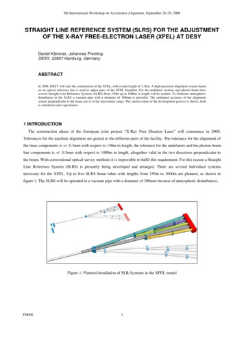
SLRS for XFEL @ DESYXFEL-survey conceptNEW PROJECTSRequired Accuracy :SLRS @ XFELÆ linac: 0.3 mm with respect to 150m lengthÆ photon beam lines: 0.5 mm w.r.t. 1000m lengthPOISSONALIGNMENTSYSTEMDIRECT LIGHTSOURCEFLASH like measurements in the tunnel sections with laser tracker connecting the tunnels to the shafts by a SLRS alternative : Wire measurement system and HLS SLRS for monochromators and other optical elements in each distribution tunnelSUMMARYGeneral data:FUTUREDEVELOPMENTTotal length of facility: approx. 3.3 kmWavelength of X-Ray radiation: 6 down to 0.085 nanometerLength of light pulses: 100 femtosecondsJ. Prenting, D. KaemtnerGeodesy @ DESYSeptember 2006
SLRS for XFEL @ DESYangle of refractionNEW PROJECTSδ [ rad ] κPz( D s )ds R DPsSLRS @ XFEL- with δn δy a constantn refractivity index of airκ local refractivity coefficientPOISSONALIGNMENTSYSTEMκ f(P,T,δTδ)y f(δTδ) y- temperature gradient perpendicular tothe beamDIRECT LIGHTSOURCEapproximation equationsSUMMARYDδnδn2δ [ rad ] ds dsδyδy0PPzFUTUREDEVELOPMENTsthusJ. Prenting, D. Kaemtnerδ [ rad ]D a 2Geodesy @ DESYandD2z a 8September 2006
SLRS for XFEL @ DESYNEW PROJECTSnumerical examples for variousδTδySLRS @ ENTSYSTEMDIRECT LIGHTSOURCESUMMARYFUTUREDEVELOPMENTδTδy 0,1 KmVergleich HöhenmessungComparisonwith altimetryδTδy 0,065 mKEntfernungRichtungsfehlerRichtungsfehlerangular error Querabweichunglateral errorangular error Querabweichunglateral 3,8218,000-2,48-11,700standard solution to minimize effects of refraction:monitoring pillars alternating on either side of the tunnel.J. Prenting, D. KaemtnerGeodesy @ DESYSeptember 2006
SLRS for XFEL @ DESYSLRS conceptNEW PROJECTSSLRS @ XFEL- several individual systems for XFEL are necessary- up to five SLR-System fromPOISSONALIGNMENTSYSTEM150m to 1000m in lengthDIRECT LIGHTSOURCESUMMARYFUTUREDEVELOPMENTJ. Prenting, D. KaemtnerGeodesy @ DESYSeptember 2006
SLRS for XFEL @ DESYSLRS conceptNEW PROJECTSPrinciple: crossing the shaftsstraightness reference for alignment, connection of the various SLRSSLRS @ XFELPOISSONALIGNMENTSYSTEMDIRECT LIGHTSOURCEvacuum pipereference target marksSUMMARYFUTUREDEVELOPMENTExperimental Hallreferencetarget marksConnection of the various SLRS- reference coordinate system transported by SLRS (by conventionaloptical survey methods, impossible to cross the shaft)- cross connection give relation between various SLRSJ. Prenting, D. KaemtnerGeodesy @ DESYSeptember 2006
SLRS for XFEL @ DESYSLRS conceptNEW PROJECTSSLRS @ XFELPOISSONALIGNMENTSYSTEMSLR-System vacuum pipe in XFELDIRECT LIGHTSOURCESUMMARYFUTUREDEVELOPMENTplanned construction for the vacuum pipebecause of air flickerJ. Prenting, D. KaemtnerGeodesy @ DESYSeptember 2006
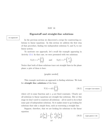
SLRS for XFEL @ DESYPoisson-Alignment-SystemNEW PROJECTSPAS from GriffithConceptual view:SLRS @ XFELPOISSONALIGNMENTSYSTEMGRIFFITH, 1989DIRECT LIGHTSOURCEoptical reference line defined by reference sphere and detectorSUMMARYFUTUREDEVELOPMENTGRIFFITH, 1989sphere on magnets can turned into the beamJ. Prenting, D. KaemtnerGeodesy @ DESYSeptember 2006
SLRS for XFEL @ DESYPoisson-Alignment-SystemNEW PROJECTSSpecification for experiments @ Argonne National Laboratory (1997):SLRS @ XFELPOISSONALIGNMENTSYSTEMLaser source:laser diode, 635nm , 3 mWEquipment:10µm pinhole from platinum iridium7,5cm diameter collimating lensDetector:quadrant silicon photovoltaic detector, -10V to 10V rangeMeasurement resolution : - 25 µm over 300m distanceFRIEDSAM, 1997DIRECT LIGHTSOURCESUMMARYFUTUREDEVELOPMENTGRIFFITH, 1989advanced system: detect many more Poisson spotsJ. Prenting, D. KaemtnerGeodesy @ DESYSeptember 2006
SLRS for XFEL @ DESYNEW PROJECTSSimulationsPoisson-Alignment-SystemVarious states of simulated images with ZEMAXSLRS @ XFELPOISSONALIGNMENTSYSTEMDIRECT LIGHTSOURCESUMMARYFUTUREDEVELOPMENTthe size and quality of the Poisson spot depends on:-task:the todiameterof the diametersphere to corresponding position in SLRSfind right sphere- their respective distance to the detectorJ. Prenting, D. KaemtnerGeodesy @ DESYSeptember 2006
SLRS for XFEL @ DESYNEW PROJECTSEmpirical testsPoisson-Alignment-SystemequipmentSLRS @ XFELPOISSONALIGNMENTSYSTEMDIRECT LIGHTSOURCEacromat (d 100mm, f 600mm)SUMMARY- tests in laboratory@desyFUTUREDEVELOPMENT- laser equipment HeNe laser (633nm, 3mW, Schaefter Kirchhoff)J. Prenting, D. KaemtnerGeodesy @ DESYSeptember 2006
SLRS for XFEL @ DESYEmpirical testsPoisson-Alignment-SystemNEW PROJECTSequipmentSLRS @ XFELPOISSONALIGNMENTSYSTEMfiber collimator (d 10mm)DIRECT LIGHTSOURCESUMMARYFUTUREDEVELOPMENTlens (d 100mm, f 120mm)two spheres with holdersJ. Prenting, D. KaemtnerGeodesy @ DESYSeptember 2006
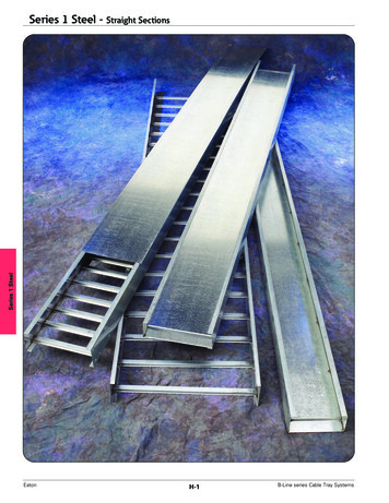
SLRS for XFEL @ DESYNEW PROJECTSSLRS @ XFELPOISSONALIGNMENTSYSTEMEmpirical testsPoisson-Alignment-Systemsetup lengthspheresdiametersdistance: sphere to CCD55m42 x 10mm2 x 12mm23m41m5m28mm3m1.7m24mm1.5mDIRECT LIGHTSOURCESUMMARYmicrometer stage for controlled translationtranslation of spheres perpendicular to beamFUTUREDEVELOPMENTJ. Prenting, D. KaemtnerGeodesy @ DESYSeptember 2006
SLRS for XFEL @ DESYNEW PROJECTS1st setup:55m in lengthPoisson-Alignment-SystemSLRS @ XFELPOISSONALIGNMENTSYSTEMDIRECT LIGHTSOURCESUMMARYFUTUREDEVELOPMENTreal image of four spots from a sony ½“ CCD-Chip cameraimpossible to analyse because of air flickerJ. Prenting, D. KaemtnerGeodesy @ DESYSeptember 2006
SLRS for XFEL @ DESYNEW PROJECTS2nd setup:5m in lengthPoisson-Alignment-SystemSLRS @ XFELPOISSONALIGNMENTSYSTEMDIRECT LIGHTSOURCESUMMARYFUTUREDEVELOPMENTcalculated difference between two consecutive imagesJ. Prenting, D. KaemtnerGeodesy @ DESYSeptember 2006
SLRS for XFEL @ DESYNEW PROJECTS2nd setup:5m in lengthPoisson-Alignment-SystemSLRS @ XFELPOISSONALIGNMENTSYSTEMDIRECT LIGHTSOURCESUMMARYFUTUREDEVELOPMENTafter a binary transformationJ. Prenting, D. KaemtnerGeodesy @ DESYSeptember 2006
SLRS for XFEL @ DESYNEW PROJECTS2nd setup:5m in lengthPoisson-Alignment-SystemSLRS @ XFELPOISSONALIGNMENTSYSTEMDIRECT LIGHTSOURCESUMMARYFUTUREDEVELOPMENTusing an edge operator: not usefulJ. Prenting, D. KaemtnerGeodesy @ DESYSeptember 2006
SLRS for XFEL @ DESYNEW PROJECTS2nd setup:5m in lengthPoisson-Alignment-SystemSLRS @ XFELPOISSONALIGNMENTSYSTEMDIRECT LIGHTSOURCESUMMARYFUTUREDEVELOPMENTresults of an ellipse operatorJ. Prenting, D. KaemtnerGeodesy @ DESYSeptember 2006
SLRS for XFEL @ DESYNEW PROJECTS2nd setup:5m in lengthPoisson-Alignment-Systemactual distance by differentimage processing methods [mm]SLRS @ XFELerror [µm]nominal [mm]differentialimagedifferencebetween twosingle imagesdifferentialimagedifferencebetween twosingle SONALIGNMENTSYSTEMDIRECT LIGHTSOURCEmean error between translation and calculated distance 12 micronsSUMMARYFUTUREDEVELOPMENTJ. Prenting, D. KaemtnerGeodesy @ DESYSeptember 2006
SLRS for XFEL @ DESYNEW PROJECTS3rd setup:1.7m in lengthPoisson-Alignment-SystemSLRS @ XFELPOISSONALIGNMENTSYSTEMDIRECT LIGHTSOURCESUMMARYFUTUREDEVELOPMENTsony camera with convex lens (d 50mm, f 50mm)J. Prenting, D. KaemtnerGeodesy @ DESYSeptember 2006
SLRS for XFEL @ DESYNEW PROJECTS3rd setup:1.7m in lengthPoisson-Alignment-SystemSLRS @ XFELPOISSONALIGNMENTSYSTEMDIRECT LIGHTSOURCESUMMARYFUTUREDEVELOPMENTmicrometer stage and two spheres with a diameter of 4mmJ. Prenting, D. KaemtnerGeodesy @ DESYSeptember 2006
SLRS for XFEL @ DESYNEW PROJECTS3rd setup:1.7m in lengthPoisson-Alignment-SystemSLRS @ XFELPOISSONALIGNMENTSYSTEMDIRECT LIGHTSOURCESUMMARYFUTUREDEVELOPMENTtwo spheres in expanded 10mm collimated laser beamJ. Prenting, D. KaemtnerGeodesy @ DESYSeptember 2006
SLRS for XFEL @ DESYNEW PROJECTS3rd setup:1.7m in lengthPoisson-Alignment-SystemSLRS @ XFELPOISSONALIGNMENTSYSTEMDIRECT LIGHTSOURCESUMMARYFUTUREDEVELOPMENTconfiguration of spheres in front of CameraJ. Prenting, D. KaemtnerGeodesy @ DESYSeptember 2006
SLRS for XFEL @ DESYNEW PROJECTS3rd setup:1.7m in lengthPoisson-Alignment-SystemSLRS @ XFELPOISSONALIGNMENTSYSTEMDIRECT LIGHTSOURCESUMMARYFUTUREDEVELOPMENTreal image with two poisson spotsJ. Prenting, D. KaemtnerGeodesy @ DESYSeptember 2006
SLRS for XFEL @ DESYNEW PROJECTS3rd setup:1.7m in lengthPoisson-Alignment-SystemSLRS @ XFELPOISSONALIGNMENTSYSTEMDIRECT LIGHTSOURCESUMMARYFUTUREDEVELOPMENTafter a binary transformationJ. Prenting, D. KaemtnerGeodesy @ DESYSeptember 2006
SLRS for XFEL @ DESYNEW PROJECTS3rd setup:1.7m in lengthPoisson-Alignment-SystemSLRS @ XFELPOISSONALIGNMENTSYSTEMDIRECT LIGHTSOURCESUMMARYFUTUREDEVELOPMENTusing ellipse operatorJ. Prenting, D. KaemtnerGeodesy @ DESYSeptember 2006
SLRS for XFEL @ DESYNEW PROJECTSSLRS @ XFELPOISSONALIGNMENTSYSTEMDIRECT LIGHTSOURCE3rd setup:1.7m in lengthPoisson-Alignment-Systemtranslation ofsphere[mm]1st epoch2nd epoch3rd epoch4th 00-21-18-15-20error of translation detection[µm]SUMMARYmean error from this setup is 17 micronsFUTUREDEVELOPMENTJ. Prenting, D. KaemtnerGeodesy @ DESYSeptember 2006
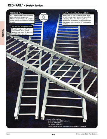
SLRS for XFEL @ DESYDirect light source SystemNEW PROJECTSSLRS @ XFELPOISSONALIGNMENTSYSTEMDIRECT LIGHTSOURCESUMMARYCCD-CameraFUTUREDEVELOPMENTJ. Prenting, D. Kaemtnerconvexsinglemodelaser withopticfibresbeam splitterGeodesy @ DESYSeptember 2006
SLRS for XFEL @ DESYDirect light source SystemNEW PROJECTSSLRS @ XFELPOISSONALIGNMENTSYSTEMDIRECT LIGHTSOURCESUMMARYFUTUREDEVELOPMENTcamera withsinglemodelaser withconvex opticfibresbeam splitterJ. Prenting, D. KaemtnerGeodesy @ DESYSeptember 2006
SLRS for XFEL @ DESYNEW PROJECTS1st setup:1.2m in lengthDirect light source SystemSLRS @ XFELPOISSONALIGNMENTSYSTEMDIRECT LIGHTSOURCESUMMARYFUTUREDEVELOPMENTconfiguration of fibre optics in front of cameraJ. Prenting, D. KaemtnerGeodesy @ DESYSeptember 2006
SLRS for XFEL @ DESYNEW PROJECTS1st setup:1.2m in lengthDirect light source SystemSLRS @ XFELPOISSONALIGNMENTSYSTEMDIRECT LIGHTSOURCESUMMARYFUTUREDEVELOPMENTfirst real image with two spots from fibre opticsJ. Prenting, D. KaemtnerGeodesy @ DESYSeptember 2006
SLRS for XFEL @ DESYNEW PROJECTS1st setup:1.2m in lengthDirect light source SystemSLRS @ XFELPOISSONALIGNMENTSYSTEMDIRECT LIGHTSOURCESUMMARYFUTUREDEVELOPMENTnext image after a translation of one fibre opticsJ. Prenting, D. KaemtnerGeodesy @ DESYSeptember 2006
SLRS for XFEL @ DESYNEW PROJECTS1st setup:1.2m in lengthDirect light source SystemSLRS @ XFELPOISSONALIGNMENTSYSTEMDIRECT LIGHTSOURCESUMMARYFUTUREDEVELOPMENTcalculated difference between two consecutive imagesJ. Prenting, D. KaemtnerGeodesy @ DESYSeptember 2006
SLRS for XFEL @ DESYNEW PROJECTS1st setup:1.2m in lengthDirect light source SystemSLRS @ XFELPOISSONALIGNMENTSYSTEMDIRECT LIGHTSOURCESUMMARYFUTUREDEVELOPMENTafter a binary transformationJ. Prenting, D. KaemtnerGeodesy @ DESYSeptember 2006
SLRS for XFEL @ DESYNEW PROJECTS1st setup:1.2m in lengthDirect light source SystemSLRS @ XFELPOISSONALIGNMENTSYSTEMDIRECT LIGHTSOURCESUMMARYFUTUREDEVELOPMENTusing ellipse operatorJ. Prenting, D. KaemtnerGeodesy @ DESYSeptember 2006
SLRS for XFEL @ DESYNEW PROJECTS1st setup:1.2m in lengthDirect light source SystemSLRS @ XFELPOISSONALIGNMENTSYSTEMtranslation offibre optic [mm]distance from imageprocessing [mm]error[µm]1st 4th image5.004.99642nd 4th image4.804.79913rd 4th image4.004.0044DIRECT LIGHTSOURCEmean error between translation and calculated distance 3 micronsSUMMARYFUTUREDEVELOPMENTJ. Prenting, D. KaemtnerGeodesy @ DESYSeptember 2006
SLRS for XFEL @ DESYNEW PROJECTS2nd setup:1.7m in lengthDirect light source SystemSLRS @ XFELPOISSONALIGNMENTSYSTEMDIRECT LIGHTSOURCESUMMARYFUTUREDEVELOPMENTconfiguration of fibre optics in front of cameraJ. Prenting, D. KaemtnerGeodesy @ DESYSeptember 2006
SLRS for XFEL @ DESYNEW PROJECTS2nd setup:1.7m in lengthDirect light source SystemSLRS @ XFELPOISSONALIGNMENTSYSTEMDIRECT LIGHTSOURCESUMMARYFUTUREDEVELOPMENTfirst real image with two spots from fibre opticsJ. Prenting, D. KaemtnerGeodesy @ DESYSeptember 2006
SLRS for XFEL @ DESYNEW PROJECTS2nd setup:1.7m in lengthDirect light source SystemSLRS @ XFELPOISSONALIGNMENTSYSTEMDIRECT LIGHTSOURCESUMMARYFUTUREDE
Straight Line Reference System (SLRS) for the adjustment of the X-ray free-electron Laser (XFEL) @ DESY IWAA 2006 SLAC, Menlo Park, California, September 2006 Outline of presentation: 1. Overview about new projects at DESY 2. SLRS-XFEL 3. Poisson Alignment System: - Introduction-Simulation