Transcription
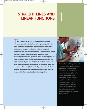
9th International Workshop on Accelerator Alignment, September 26-29, 2006STRAIGHT LINE REFERENCE SYSTEM (SLRS) FOR THE ADJUSTMENTOF THE X-RAY FREE-ELECTRON LASER (XFEL) AT DESYDaniel Kämtner, Johannes PrentingDESY, 22607 Hamburg, GermanyABSTRACTIn 2008, DESY will start the construction of the XFEL, with a total length of 3.3km. A high-precision alignment system basedon an optical reference line is used to adjust parts of the XFEL beamline. For the undulator sections and photon beam linesseveral Straight Line Reference Systems (SLRS) from 150m up to 1000m in length will be needed. To eliminate atmosphericdisturbance in the SLRS a vacuum pipe with a diameter of 300mm is provided. The estimated accuracy of the alignmentsystem perpendicular to the beam axis is in the micrometer range. The current status of the development process is shown; bothin simulation and experiments.1 INTRODUCTIONThe construction phase of the European joint project “X-Ray Free Electron Laser” will commence in 2008.Tolerances for the machine alignment are geared to the different parts of the facility. The tolerance for the alignment ofthe linac components is /- 0.3mm with respect to 150m in length, the tolerance for the undulators and the photon beamline components is /- 0.5mm with respect to 1000m in length, altogether valid in the two directions perpendicular tothe beam. With conventional optical survey methods it is impossible to fulfil this requirement. For this reason a StraightLine Reference System (SLRS) is presently being developed and arranged. There are several individual systemsnecessary for the XFEL. Up to five SLRS beam tubes with lengths from 150m to 1000m are planned, as shown infigure 1. The SLRS will be operated in a vacuum pipe with a diameter of 300mm because of atmospheric disturbances.Figure 1: Planned installation of SLR-Systems in the XFEL tunnelTH0081
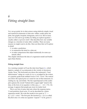
9th International Workshop on Accelerator Alignment, September 26-29, 20062 SLRS BASIC PRINCIPLEThere are two types of SLRS with different target types which are currently being evaluated. Both use a He-Ne laserwith a wavelength of 633 nm as a light source. The Poisson Alignment system uses the diffraction patterns of spheres,the Active Light Source system uses single mode fiber ends as a target. The optical reference line is either defined byone selected ball and the center spot of its diffraction pattern at a CCD-Chip or by the center of a 5µm fiber and thecenter of its image at the CCD-Chip.3 POISSON ALIGNMENT SYSTEM3. 1 BackgroundGriffith [1] and Friedsam et al. [2] have already reported fundamental results of analysis and experiments concerningthe subject of the Poisson Alignment System. In general, the size and quality of the Poisson Spot depends on thediameter of the sphere or the slice and their respective distance to the detector (see figure 2).Figure 2: Dependence of the Poisson Spot on the distance to the detectorThe shorter the distance to the detector the lower the spot diameter will be. The phenomenon of the Poisson Spot canbe explained by the wave-particle duality of light. A more detailed formula for calculating the size of the Poisson Spotis given in by equations (1) and (2). “We can construct the light field diffracted by a disc with Babinet's principle andthe results from a circular aperture. It consists of just the difference between the non-diffracted field, in the most simplecase a planar wave, and the complementary field, which originates from a circular aperture.” [3]TH0082
9th International Workshop on Accelerator Alignment, September 26-29, 2006(1)with:ε(r) amplitude of the electric fieldεSeikz planar wave frontk 2π/λ wave vactor with λ as wave lenghtκ ka2/z wave frequenz with a the radius of the circular aperture and z the distance between circular aperture anddetector“The diffraction image at a circular obstacle consists of the superposition of a planar wave and a diffraction wave ofthe circular aperture.”[3](2)with:ε(r 0) amplitude of the electric field on the optical axis (r 0)I(r 0) intensity of the Poisson Spot on the optical axisc speed of lightЄ0 dielectic in vacuum 13. 2 ZEMAX SimulationTo obtain general information concerning the technical feasibility of the alignment system simulations usingZEMAX (software for the design and optimization of optical systems,) have been performed. Simulations for the SLRSwere performed using pipe lengths of 150m, 300m and 1000m. A Gaussian beam profile with λ 633nm and a FullWidth Half-Maximum (FWHM) of 100mm was used to calculate the diffraction patterns. During the first simulationsno optics for laser beam expansion or for focusing has been included.In order to acquire information about the scale and a possible rotation every machine component will get equippedwith two spheres within a fixed distance. The interspace between these two spheres will be precisely calibrated.The figures 3(a) and 3(b) show the results of the simulation for eight spheres with diameters from 10mm up to 30mmpositioned at various distances within a 150m long system. In detail the diameters and positions have been: 30mmspheres at 145 and 105m distance, 23mm spheres at 45m distance and 10mm spheres at 5m distance between target andthe detector.TH0083
9th International Workshop on Accelerator Alignment, September 26-29, 2006Figure 3 (a): ZEMAX simulation with 8 spheres; (b): Simulation with 8 spheres and holdersThis setup is the typical setup for crossing the shafts. Additional system lengths for the photon beam lines have beencalculated. The results show the technical feasibility of the SLR-System over 1000 metres in length.3. 3 Empirical tests and resultsFor the first set of empirical tests, a Class IIIa 633nm He-Ne laser diode beam with coupled single mode fiber and apotentiometer adjustable output power of 3mW was used. The setup also included a fiber collimator with a collimatedbeam diameter of 10mm, a lens with d 120mm, f 100mm and an achromat with d 100mm, f 600mm. The apparatusserved to expand the beam to produce a 100mm beam diameter as shown in figure 4. For the image capturing we used aSony XCD-C700 with a 1/2” CCD-Chip and a resolution of 1024x768 pixels.TH0084
9th International Workshop on Accelerator Alignment, September 26-29, 2006Figure 4: First setup for feasibility testsIn the first trial, four spheres with diameters of 10mm and 12mm were positioned at 23m and 41m in front of thecamera. The entire length of the 100mm flared, collimated laser beam track was 55m. The image captured by the CCDChip is shown in figure 5. Of course it has been impossible to evaluate the translation of a sphere in the imagesequences because of atmospheric disturbances, but the example gave a good impression of the image quality.Figure 5: Image with four poisson spots on the 55m setupTH0085
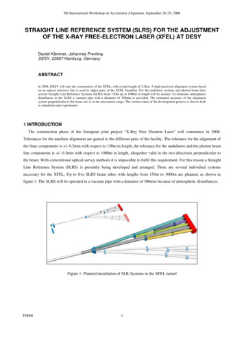
9th International Workshop on Accelerator Alignment, September 26-29, 2006Until the vaccum system will be installed, we use shorter tracks to check the image processing algorithms. The nexttrack has been setup with a length of 5m overall, two spheres with 8mm diameter were positioned 3m in front of thecamera. One sphere was mounted on a linear translation stage, shown in figure 6(a), with a micrometer screw forcontrolled translation perpendicular to the beam. Figure 6(b) shows one example image from the two Poisson Spots 3min front of the camera.Figure 6 (a): Micrometer stage with mounted sphere; (b): image of two spheres with a diameter of 8mmA couple of different methods have been used for image processing. One issue was to immediately start with readyto-use free software (ImgageJ). At first a differential image between two consecutive images has been calculated.Figure 7(a) shows the result of this process. After a binary transformation (fig. 7b), edge operators (fig. 7c) and ellipseoperators (fig. 7d) have been tested to calculate the distance between the two spots in the differential image.A second method started with the detection of the centre of the Poisson Spots in the single images. Then the distancesbetween the fixed spot and the moving spot were calculated from the image coordinates. The translation of a sphere canthen be calculated by comparing the distances in the consecutive images. Both the edge operator and the ellipseoperator did not yet reach the demands of accuracy we needed. We then switched to using an algorithm calculating thecenter of mass of the sinlge spots. The nominal translation of the moving sphere has been measured with a laserinterferometer.TH0086
9th International Workshop on Accelerator Alignment, September 26-29, 2006Figure 7 (a): Difference between two images; (b): Result of a binary transformation; (c): Result after using the edgeoperator; (d): Result after using the ellipse operatorThe mean error between the nominal translation and the calculated distance was 12µm for the setup with 5m inlength. On a different setup with a length of 1.7m the mean error of translation detection has been 17µm. A range oftranslations from 0.20mm up to 2.00mm have been measured in multiple epochs.3. 4 Potential nonconformitiesThe aim is to develop the SLR-System to be as simple as possible and therefore be as unsusceptible to error aspossible. To generate the Poisson Spot a round, thin and opaque slice in the collimated beam is equivalent to an opaquesphere.The coherence length of the laser defines the maximum possible path difference for the development of theinterference pattern. By using a slice the maximum acceptable tilting where interference is still possible is definedthrough the coherence length of the laser. Using a sphere is more productive as it is insensitive to tilt angles.A tilt of the sphere around an axis perpendicular to the beam direction gives a cosine-error and influences the positionof the Poisson Spot of the CCD-Chip. It can be calculated by observing a pair of spheres for every machine component.The several optics such as lenses and achromats in the collimated beam path produced back-reflections, whichimpaired the quality of the beam. These kinds of errors depend on the coherence length of the utilised laser. A laserwith very short coherence lengths e.g. 300µm minimizes these effects.3. 5 Differences to former Poisson-Alignment-SystemsThe Poisson-Alignment-System conceptualized by Griffith [1] used a quad cell position detector to detect themaximum of the Poisson Spot. Based on the advanced technology today it is possible to use a CCD-Chip as detector.This development gives the possibility to analyse interference patterns and Poisson Spots using image processingsoftware. The center of the Poisson Spot can be calculated with sub pixel accuracy by using cross correlation algorithms(Prenting [4]).TH0087
9th International Workshop on Accelerator Alignment, September 26-29, 20064 DIRECT LIGHT SOURCE SYSTEM4. 1 Basic principleThe direct light source system is based on fiber optics as an active light source, as shown in figure 8. The light sourcefor the fibers is a laser coupled to a fiber optical beam splitter. A convex lens and a CCD-Chip are use to capture theimage from the spots.Figure 8: Basic concept of the direct light source system4. 2 EquipmentFor the first studies we used a low noise laser diode beam source: the 51FCM from Schäfter Kirchhoff which isinternally RF-modulated with a frequency of 0.4 GHz, shown in figure 9(a). This laser has a short coherence length of300µm with λ 641.4nm and an adjustable output power of 5mW. The laser beam is coupled into a single mode fiber.Furthermore a fiber optical beam splitter with four laser attenuators (SuK 48AT) to give precise laser output powerreduction for each single mode fiber connector is used, shown in figure 9(a). To mount the single mode fiber optics weused FC-APC adapters, shown in figure 9(b).The image capturing was done by using a convex lens and a CCD-Chip camera, shown in figure 9(c).TH0088
9th International Workshop on Accelerator Alignment, September 26-29, 2006Figure 9 (a): 51FCM laser with beam splitter; (b): Fiber Optics; (c): Convex lens with CCD-Chip camera4. 3 Empirical tests and resultsWith two setups of 1.2m and 1.7m in length we tested the technical feasibility of the direct light source system in ourstraightness systems laboratory at DESY. Figure 10(a) shows the laser, the optical beam splitter and the fiber opticsmounted on a carriage and a micrometer stage. The configuration of the fiber optics for one of these tests in front of thecamera is shown in figure 10(b). For the controlled translation perpendicular to the beam, one fiber optic was mountedon a micrometer stage. The image processing was identical to that used for the Poisson-Alignment-System. After abinary transformation we used an ellipse operator to calculate the centre of the spots in every single image. Finally wecalculated the distance of translation using the coordinates of the spots in two consecutive images.Figure 10 (a): Laser with beam splitter and fiber optics; (b): Configuration of the fiber Optics in front of the cameraIn the first setup with a length of 1.2m the mean error between the actual distance translated and the calculateddistance was 3µm. For the second setup with a length of 1.7m the mean error was 10µm. All tests have been measuredin four epochs with translation of the fiber optics from 0.20mm up to 2.00mm perpendicular to the beam.TH0089
9th International Workshop on Accelerator Alignment, September 26-29, 20065 PERSPECTIVEThe first main task in the future development is to work out advantages and the disadvantages of the Poissonalignment system and the Active-Light-Source alignment system. That includes image processing with the tests ofvarious algorithms especially cross correlation, precise measurement of the translation using an interferometer andsimulations for expanding and focusing of the laserbeam using ZEMAX software. The cross correlation algorithm willdeliver an accuracy of less than a tenth of
several Straight Line Reference Systems (SLRS) from 150m up to 1000m in length will be needed. To eliminate atmospheric disturbance in the SLRS a vacuum pipe with a diameter of 300mm is provided. The estimated accuracy of the alignment system perpendicular to the beam axis is in the micrometer range. The current status of the development process is shown; both