Transcription
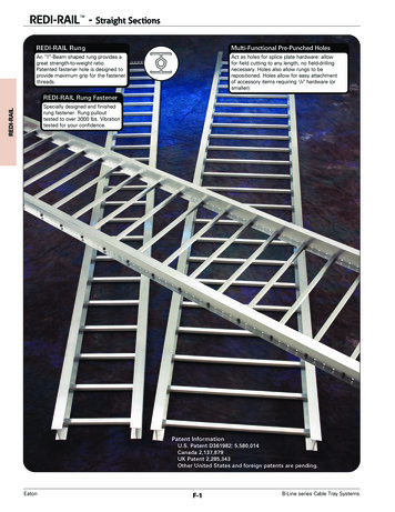
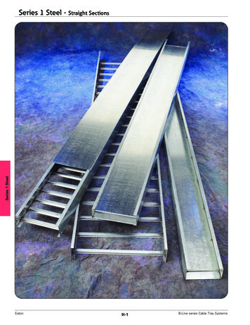
Series 1 SteelSeries 1 Steel - Straight SectionsEatonH-1B-Line series Cable Tray Systems
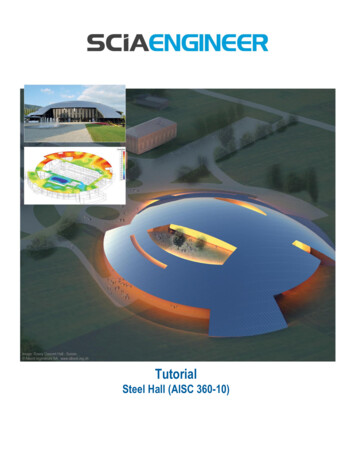
Series 1 Steel - Accessories & FittingsSeries 1 SteelHow The Service Advisor WorksWe know that your time is important! That’s why the color-coding system in this catalog is designed to help youselect products that fit your service needs. Products are marked to indicate the typical lead time for orders of 50pieces or less.Customer: How do I select my straight sections. covers, or fittings so that I get the quickest turnaround?Service Advisor: Each part of our selection chart is shown in colors. If any section of a part number is a differentcolor, the part will typically ship with the longer lead time represented by the colors.Green Fastest shipped itemsBlack Normal lead-time itemsRed Normally long lead-time itemsExample:156G09-24-144Part will have a longlead time because of the156G material.Changing the part number from 156G to 156P will change the coding to black for all sections and reduce lead time.B-Line series Cable Tray SystemsH-2Eaton
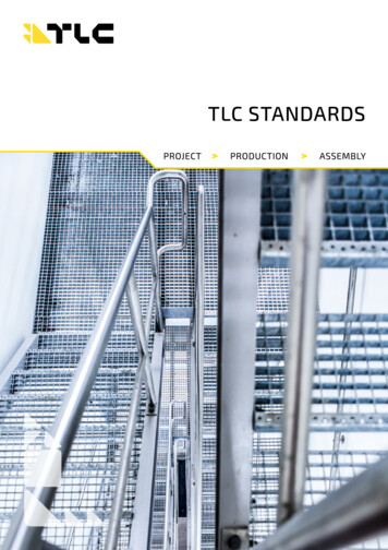
Series 1 Steel - Straight Sections3" NEMA VE 1 Loading DepthActual Loading Depth 3.077"Straight Section Part NumberingPrefixExample: 148 P 09 - 24 - 144SeriesMaterialType148P Pre-GalvanizedSteelLadder06 6" rung spacing09 9" rung spacing12 12" rung spacingG Hot DipGalvanizedAfter FabricationSteelRungSpacingTrough6" thru 24" wide04 Vented BottomSB Non-Ventilated BottomForside rail& rung data,see chart onpages APP-6 & APP-7Length 144 12 ft.¡ 120 10 ft.06 6"09 9"12 12"18 18"24 24"30 30"36 36" PrimaryLength.Length.¡SecondarySee page C-23 forexplanation of lengths.See page APP-1 for additional rung options. *SB available for all widths.Series 1 SteelOverall Width(Width 1/8”)WidthLadder Type(Specify Rung Spacing)Ventilated BottomNon-VentilatedValues are based on simple beam tests per NEMA VE 1 on 36" wide cable tray with rungs spaced on 12" centers. The publishedload safety factor is 1.5. To convert 1.5 safety factor to 2.0, multiply the published load by 0.75. To obtain mid-span deflection,multiply a load by the deflection multiplier. Cable tray must be supported on spans shorter than or equal to the length of the cabletray being installed.B-Line SeriesNEMA, CSA & ULSIde Rail Dimensions Classifications.8751483.6253.07718 gaugeNEMA: 12A, 8CCSA: C1-3mUL Cross-SectionalArea: 0.40 in2SpanLoadftlbs/ft681012204*1157351Deflection Design FactorsMultiplier for Two Rails0.00110.00360.00870.0181Area 0.510 in2Sx 0.480 in3Ix 0.890 in4SpanLoadmeterskg/mDeflection Design FactorsMultiplier for Two Rails1.8304*0.019Area 3.290 cm22.41710.061Sx 7.870 cm33.01090.149Ix 37.04 cm43.7760.309*When using 12" rung spacing load capacity is limited to 195 lbs/ft (290.16 kg/m) for 36" tray width. When cable trays are used incontinuous spans, the deflection of the cable tray is reduced by as much as 50%.Design factors: Ix Moment of Inertia, Sx Section Modulus.Green Fastest shipped itemsEatonBlack Normal lead-time itemsH-3Red Normally long lead-time itemsB-Line series Cable Tray Systems
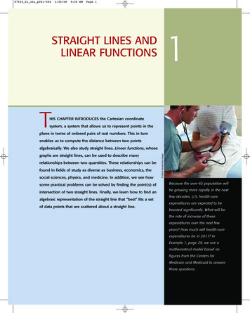
Series 1 Steel - Straight Sections4" NEMA VE 1 Loading DepthActual Loading Depth 3.628"Straight Section Part NumberingPrefixExample: 156 P 09 - 24 - 144SeriesMaterialType156P Pre-GalvanizedSteelLadder06 6" rung spacing09 9" rung spacing12 12" rung spacingG Hot DipGalvanizedAfter FabricationSteelTrough6" thru 24" wide04 Vented BottomSB Non-Ventilated BottomRungSpacingOverall Width(Width 1/8”)WidthForside rail& rung data,see chart onpages APP-6 & APP-7Length 144 12 ft.¡ 120 10 ft.06 6"09 9"12 12"18 18"24 24"30 30"36 36" PrimaryLength.Length.¡SecondarySee page C-23 forexplanation of lengths.See page APP-1 for additional rung options. *SB available for all widths.Series 1 SteelVentilated BottomLadder Type(Specify Rung Spacing)Non-VentilatedValues are based on simple beam tests per NEMA VE 1 on 36" wide cable tray with rungs spaced on 12" centers. Cable trays willsupport without collapse a 200 lb. (90.7 kg) concentrated load over and above the published loads. The published load safety factoris 1.5. To convert 1.5 safety factor to 2.0, multiply the published load by 0.75. To obtain mid-span deflection, multiply a load by thedeflection multiplier. Cable tray must be supported on spans shorter than or equal to the length of the cable tray being installed.B-Line SeriesNEMA, CSA & ULSIde Rail Dimensions Classifications.8751564.1883.62816 gaugeNEMA: 12B, 8CCSA: C1-3mUL Cross-SectionalArea: 0.40 in2SpanLoadftlbs/ft681012304*17110976Deflection Design FactorsMultiplier for Two Rails0.00070.00210.00510.0011Area 0.690 in2Sx 0.724 in3Ix 1.517 in4SpanLoadmeterskg/mDeflection Design FactorsMultiplier for Two Rails1.8452*0.011Area 4.390 cm22.42540.036Sx 11.860 cm33.01630.087Ix 63.140 cm43.71130.181*When using 12" rung spacing, load capacity is limited to 234 lbs/ft (348.192 kg/m) for 30" tray width and 195 lbs/ft (290.16kg/m) for 36" tray width. When trays are used in continuous spans, the deflection of the tray is reduced by as much as 50%.Design factors: Ix Moment of Inertia, Sx Section Modulus.Green Fastest shipped itemsBlack Normal lead-time itemsRed Normally long lead-time itemsAll dimensions in parentheses are millimeters unless otherwise specified.B-Line series Cable Tray SystemsH-4Eaton
Series 1 Steel - Straight Sections5" NEMA VE 1 Loading DepthActual Loading Depth 4.628"Straight Section Part NumberingPrefixExample: 166 P 09 - 24 - 144SeriesMaterialType166P Pre-GalvanizedSteelLadder06 6" rung spacing09 9" rung spacing12 12" rung spacingG Hot DipGalvanizedAfter FabricationSteelTrough6" thru 24" wide04 Vented BottomSB Non-Ventilated BottomRungSpacingForside rail& rung data,see chart onpages APP-6 & APP-7Length 144 12 ft.¡ 120 10 ft.06 6"09 9"12 12"18 18"24 24"30 30"36 36" PrimaryLength.Length.¡SecondarySee page C-23 forexplanation of lengths.See page APP-1 for additional rung options. *SB available for all widths.Series 1 SteelOverall Width(Width 1/8”)WidthVentilated BottomLadder Type(Specify Rung Spacing)Non-VentilatedValues are based on simple beam tests per NEMA VE 1 on 36" wide cable tray with rungs spaced on 12" centers. Cable trays willsupport without collapse a 200 lb. (90.7 kg) concentrated load over and above published loads. The published load safety factor is1.5. To convert 1.5 safety factor to 2.0, multiply the published load by 0.75. To obtain mid-span deflection, multiply a load by thedeflection multiplier. Cable tray must be supported on spans shorter than or equal to the length of the cable tray being installed.B-Line SeriesNEMA, CSA & ULSIde Rail Dimensions Classifications.7501665.1884.62816 gaugeNEMA: 12B, 8CCSA: C1-3mUL Cross-SectionalArea: 0.70 in2SpanLoadftlbs/ft681012308*17311177Deflection Design FactorsMultiplier for Two Rails0.00040.00130.00320.0067Area 0.770 in2Sx 0.930 in3Ix 2.400 in4SpanLoadmeterskg/mDeflection Design FactorsMultiplier for Two Rails1.8458*0.007Area 4.970 cm22.42580.023Sx 15.240 cm33.01650.055Ix 99.900 cm43.71150.114*When using 12" rung spacing, the load capacity is limited to 234 lbs/ft (348.192 kg/m) for 30" tray width and 195 lbs/ft (290.16 kg/m)for 36" tray width. When trays are used in continuous spans, the deflection of the tray is reduced by as much as 50%.Design factors: Ix Moment of Inertia, Sx Section Modulus.Green Fastest shipped itemsBlack Normal lead-time itemsRed Normally long lead-time itemsAll dimensions in parentheses are millimeters unless otherwise specified.EatonH-5B-Line series Cable Tray Systems
Series 1 Steel - Straight Sections6" NEMA VE 1 Loading DepthActual Loading Depth 5.628"Straight Section Part NumberingPrefixExample: 176 P 09 - 24 - 144SeriesMaterialType176P Pre-GalvanizedSteelLadder06 6" rung spacing09 9" rung spacing12 12" rung spacingG Hot DipGalvanizedAfter FabricationSteelTrough6" thru 24" wide04 Vented BottomSB Non-Ventilated BottomRungSpacingOverall Width(Width 1/8”)WidthForside rail& rung data,see chart onpages APP-6 & APP-7Length 144 12 ft.¡ 120 10 ft.06 6"09 9"12 12"18 18"24 24"30 30"36 36" PrimaryLength.Length.¡SecondarySee page C-23 forexplanation of lengths.See page APP-1 for additional rung options. *SB available for all widths.Series 1 SteelVentilated BottomLadder Type(Specify Rung Spacing)Non-VentilatedValues are based on simple beam tests per NEMA VE 1 on 36" wide cable tray with rungs spaced on 12" centers. Cable trays willsupport without collapse a 200 lb. (90.7 kg) concentrated load over and above published loads. The published load safety factor is1.5. To convert 1.5 safety factor to 2.0, multiply published load by 0.75. To obtain mid-span deflection, multiply a load by thedeflection multiplier. Cable tray must be supported on spans shorter than or equal to the length of the cable tray being installed.B-Line SeriesNEMA, CSA & ULSIde Rail Dimensions Classifications.7501766.1885.62816 gaugeNEMA: 12B, 8CCSA: 137kg/m3.7mUL Cross-SectionalArea: 0.70 in2SpanLoadftlbs/ft8101219412486Deflection Design FactorsMultiplier for Two Rails0.00080.00200.0042Area 0.890 in2Sx 1.230 in3Ix 3.800 in4SpanLoadmeterskg/mDeflection Design FactorsMultiplier for Two Rails2.4458*0.014Area 5.740 cm23.02580.035Sx 20.160 cm33.71650.072Ix 158.200 cm4When cable trays are used in continuous spans, the deflection of the tray is reduced by as much as 50%.Design factors: Ix Moment of Inertia, Sx Section Modulus.Green Fastest shipped itemsBlack Normal lead-time itemsRed Normally long lead-time itemsAll dimensions in parentheses are millimeters unless otherwise specified.B-Line series Cable Tray SystemsH-6Eaton
Series 1 Steel - AccessoriesStandard (L-Shaped) Splice Plates One pair including hardware provided with each section.(Expansion splice quantity subtracted) Furnished in pairs with hardware. Prepackaged in pairs in a plastic bag, with hardware. 4-hole pattern L-shaped splice plates. L-shaped lay-in design. (*) Insert ZN or GTraySeriesCatalog 7TraySeriesCatalog 7TraySeriesCatalog -1/29(*)-2007-1/2TraySeriesCatalog No.156 to148166 to 156 or 148176 to 156 or 148176 to atalog 8026Expansion (L-Shaped) Splice Plates Expansion plates allow for one inch expansionor contraction of the cable tray, or where expansionjoints occur in the supporting structure. Bonding Jumpers are required on each side rail.Order Separately. L-shaped lay-in design. Furnished in pairs with hardware. (*) Insert ZN or GUniversal Splice Plates Used to splice to existing cable tray systems. Furnished in pairs with hardware. (*) Insert P or GSeries 1 SteelStep Down Splice Plates These splice plates are offered for connecting cabletray sections having side rails of different heights. Furnished in pairs with hardware. (*) Insert ZN or GVertical Adjustable Splice Plates These plates provide for changes in elevationthat do not conform to standard vertical fittings. Bonding jumpers not required. Furnished in pairs with hardware. (*) Insert ZN or G (**) Insert P or GHorizontal Adjustable Splice PlatesRequires supports within24” on both sides, per NEMA VE 2.9(*)-803(X)-12 or 9(*)-803(X)-36One pair splice plates with extensions. Offered to adjust a cable tray run for changesin direction in a horizontal plane that donot conform to standard horizontal fittings. Furnished in pairs with hardware. Bonding jumpers not required. (*) Insert ZN or G (X) Insert 4 for series 148 or 156,5 for series 166, or 6 for series 176LLCable TrayEnd CutMiteredNot miteredNot miteredTrayWidthThru 36"Thru 12"Thru 36"'L'N/A16"41"Requires supports within 24”on both sides, per NEMA VE 2.9(*)-803(X)Splices onlyGreen Fastest shipped )-36Black Normal lead-time itemsRed Normally long lead-time itemsAll dimensions in parentheses are millimeters unless otherwise specified.EatonH-7B-Line series Cable Tray Systems
Series 1 Steel - AccessoriesBranch Pivot Connectors Branch from existing cable tray runs at any point. Pivot to any required angle. UL Classified for grounding(bonding jumpers are not required). Furnished in pairs with hardware. (*) Insert ZN or GTraySeriesCatalog No.156 to log 8065-(‡)9(*)-8066-(‡)TraySeriesCatalog 6TraySeriesCatalog 8075-(‡)9(*)-8076-(‡)Offset Reducing Splice Plate This plate is used for joining cable trays having differentwidths. When used in pairs they form a straight reduction;when used singly with a standard splice plate they forman offset reduction. Furnished as one plate with hardware. (‡) Insert reduction (*) Insert P or GTray to Box Splice Plates Used to attach the end of a cable trayrun to a distribution box or control panel. Furnished in pairs with hardware. (*) Insert P or GFrame Type Box ConnectorBlind End This plate forms a closure for a dead end cable tray. Furnished as one plate with hardware. (‡) Insert tray width (*) Insert P or GTraySeriesCatalog 8085-(‡)9(*)-8086-(‡)Tray HardwarePre-Galvanized Tray HardwareCatalog No.RNCB 3/8"-16 x 3/4" ZnpltRibbed Neck Carriage Bolt ASTM A307 Grade AHot Dip Galvanized Tray HardwareCatalog No.RNCB 3/8"-16 x 3/4" CZ Ribbed NeckCarriage Bolt Chromium Zinc ASTM F-1136-88Catalog No.SFHN 3/8"-16 ZnpltSerrated Flange Hex Nut ASTM A563Grade ACatalog No.SFHN 3/8"-16 CZ Serrated Flange Hex NutChromium Zinc ASTM F-1136-88Finish: Zinc Plated ASTM B633, SC1Green Fastest shippe
Green Fastest shipped items Black Normal lead-time items Red Normally long lead-time items Example: 156G 09 - 24 - 144 Part will have a long lead