Transcription
Configuring LAGCHAPTERS1. LAG2. LAG Configuration3. Configuration Examples4. Appendix: Default Parameters
This guide applies to:T1500G-8T v2 or above, T1500G-10PS v2 or above, T1500G-10MPS v2 or above, T1500-28PCT v3 or above,T1600G-18TS v2 or above, T1600G-28TS v3 or above, T1600G-28PS v3 or above, T1600G-52TS v3 or above,T1600G-52PS v3 or above, T1700X-16TS v3 or above, T1700G-28TQ v3 or above, T2500G-10TS v2 or above,T2600G-18TS v2 or above, T2600G-28TS v3 or above, T2600G-28MPS v3 or above, T2600G-28SQ v1 orabove, T2600G-52TS v3 or above.
1LAG1.1OverviewWith LAG (Link Aggregation Group) function, you can aggregate multiple physical ports intoa logical interface, increasing link bandwidth and providing backup ports to enhance theconnection reliability.1.2Supported FeaturesYou can configure LAG in two ways: static LAG and LACP (Link Aggregation ControlProtocol).Static LAGThe member ports are manually added to the LAG.LACPThe switch uses LACP to implement dynamic link aggregation and disaggregation byexchanging LACP packets with its peer device. LACP extends the flexibility of the LAGconfiguration.
2LAG ConfigurationTo complete LAG configuration, follow these steps:1) Configure the global load-balancing algorithm.2) Configure Static LAG or LACP.Configuration Guidelines Ensure that both ends of the aggregation link work in the same LAG mode. For example,if the local end works in LACP mode, the peer end should also be set as LACP mode. Ensure that devices on both ends of the aggregation link use the same number ofphysical ports with the same speed, duplex, jumbo and flow control mode. A port cannot be added to more than one LAG at the same time. LACP does not support half-duplex links. One static LAG supports up to eight member ports. All the member ports share thebandwidth evenly. If an active link fails, the other active links share the bandwidthevenly. One LACP LAG supports multiple member ports, but at most eight of them can worksimultaneously, and the other member ports are backups. Using LACP protocol, theswitches negotiate parameters and determine the working ports. When a working portfails, the backup port with the highest priority will replace the faulty port and start toforward data. For the functions like IGMP Snooping, 802.1Q VLAN, MAC VLAN, Protocol VLAN, VLANVPN, GVRP, Voice VLAN, STP, QoS, DHCP Snooping and Flow Control, the member potof an LAG follows the configuration of the LAG but not its own. The configurations ofthe port can take effect only after it leaves the LAG. The port enabled with Port Security, Port Mirror, MAC Address Filtering or 802.1Xcannot be added to an LAG, and the member port of an LAG cannot be enabled withthese functions.
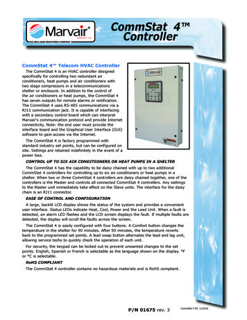
2.1Using the GUI2.1.1 Configuring Load-balancing AlgorithmChoose the menu L2 FEATURES Switching LAG LAG Table to load the followingpage.Figure 2-1Global ConfigIn the Global Config section, select the load-balancing algorithm (Hash Algorithm), thenclick Apply.Hash AlgorithmSelect the Hash Algorithm, based on which the switch can choose the port to forwardthe received packets. In this way, different data flows are forwarded on differentphysical links to implement load balancing. There are six options:SRC MAC: The computation is based on the source MAC addresses of the packets.DST MAC: The computation is based on the destination MAC addresses of thepackets.SRC MAC DST MAC: The computation is based on the source and destination MACaddresses of the packets.SRC IP: The computation is based on the source IP addresses of the packets.DST IP: The computation is based on the destination IP addresses of the packets.SRC IP DST IP: The computation is based on the source and destination IPaddresses of the packets.Tips: Load-balancing algorithm is effective only for outgoing traffic. If the data stream is notwell shared by each link, you can change the algorithm of the outgoing interface. Please properly choose the load-balancing algorithm to avoid data stream transferringonly on one physical link. For example, Switch A receives packets from several hostsand forwards them to the Server with the fixed MAC address, you can set the algorithm
as “SRC MAC” to allow Switch A to determine the forwarding port based on the sourceMAC addresses of the received packets.Figure 2-2Hash Algorithm ConfigurationSwitch ASwitch BHostsServer2.1.2 Configuring Static LAG or LACPFor one port, you can choose only one LAG mode: Static LAG or LACP. And make sure bothends of a link use the same LAG mode. Configuring Static LAGChoose the menu L2 FEATURES Switching LAG Static LAG to load the followingpage.Figure 2-3Static LAGFollow these steps to configure the static LAG:1) Select an LAG for configuration.Group IDSelect an LAG for static LAG configuration.DescriptionDisplays the LAG mode.2) Select the member ports for the LAG. It is multi-optional.3) Click Apply.
Note:Clearing all member ports will delete the LAG. Configuring LACPChoose the menu L2 FEATURES Switching LAG LACP to load the following page.Figure 2-4LACP ConfigFollow these steps to configure LACP:1) Specify the system priority for the switch and click Apply.System PrioritySpecify the system priority for the switch. A smaller value means a higher priority.To keep active ports consistent at both ends, you can set the system priorityof one device to be higher than that of the other device. The device with higherpriority will determine its active ports, and the other device can select its activeports according to the selection result of the device with higher priority. If the twoends have the same system priority value, the device with a smaller MAC addresshas the higher priority.2) Select member ports for the LAG and configure the related parameters. Click Apply.Group IDSpecify the group ID of the LAG. Note that the group ID of other static LAGscannot be set as this value.The valid value of the Group ID is determined by the maximum number of LAGssupported by your switch. For example, if your switch supports up to 14 LAGs,the valid value ranges from 1 to 14.
Port Priority(0-65535)Specify the Port Priority. A smaller value means a higher port priority.ModeSelect the LACP mode for the port.The port with higher priority in an LAG will be selected as the working port toforward data, and at most eight ports can work simultaneously. If two portshave the same priority value, the port with a smaller port number has the higherpriority.In LACP, the switch uses LACPDU (Link Aggregation Control Protocol Data Unit)to negotiate the parameters with the peer end. In this way, the two ends selectactive ports and form the aggregation link. The LACP mode determines whetherthe port will take the initiative to send the LACPDU. There are two modes:Passive: The port will not send LACPDU before receiving the LACPDU from thepeer end.Active: The port will take the initiative to send LACPDU.Status2.2Enable the LACP function of the port. By default, it is disabled.Using the CLI2.2.1 Configuring Load-balancing AlgorithmFollow these steps to configure the load-balancing algorithm:Step 1configureStep 2port-channel load-balance { src-mac dst-mac src-dst-mac src-ip dst-ip src-dst-ip }Enter global configuration mode.Select the Hash Algorithm. The switch will choose the ports to transfer the packets basedon the Hash Algorithm. In this way, different data flows are forwarded on different physicallinks to implement load balancing.src-mac: The computation is based on the source MAC addresses of the packets.dst-mac: The computation is based on the destination MAC addresses of the packets.src-dst-mac: The computation is based on the source and destination MAC addresses ofthe packets.src-ip: The computation is based on the source IP addresses of the packets.dst-ip: The computation is based on the destination IP addresses of the packets.src-dst-ip: The computation is based on the source and destination IP addresses of thepackets.Step 3show etherchannel load-balanceVerify the configuration of load-balancing algorithm.
Step 4endStep 5copy running-config startup-configReturn to privileged EXEC mode.Save the settings in the configuration file.The following example shows how to set the global load-balancing mode as annel load-balance src-dst-macSwitch(config)#show etherchannel load-balanceEtherChannel Load-Balancing Configuration: src-dst-macEtherChannel Load-Balancing Addresses Used Per-Protocol:Non-IP: Source XOR Destination MAC addressIPv4: Source XOR Destination MAC addressIPv6: Source XOR Destination MAC addressSwitch(config)#endSwitch#copy running-config startup-config2.2.2 Configuring Static LAG or LACPYou can choose only one LAG mode for a port: Static LAG or LACP. And make sure bothends of a link use the same LAG mode. Configuring Static LAGFollow these steps to configure static LAG:Step 1configureStep 2interface {fastEthernet port range fastEthernet port-list gigabitEthernet port rangegigabitEthernet port-list ten-gigabitEthernet port range ten-gigabitEthernet port-list ]Enter global configuration mode.Enter interface configuration mode.Step 3channel-group num mode onAdd the port to a static LAG.num : The group ID of the LAG.
Step 4show etherchannel num summaryVerify the configuration of the static LAG.num : The group ID of the LAG.Step 5endStep 6copy running-config startup-configReturn to privileged EXEC mode.Save the settings in the configuration file.The following example shows how to add ports1/0/5-8 to LAG 2 and set the mode as staticLAG:Switch#configureSwitch(config)#interface range gigabitEthernet 1/0/5-8Switch(config-if-range)#channel-group 2 mode onSwitch(config-if-range)#show etherchannel 2 summaryFlags: D - downP - bundled in port-channelU - in useI - stand-aloneH - hot-standby(LACP only)s - suspendedR - layer3S - layer2u - unsuitable for bundlingf - failed to allocate aggregatorw - waiting to be Gi1/0/5(D) Gi1/0/6(D) Gi1/0/7(D) Gi1/0/8(D)Switch(config-if-range)#endSwitch#copy running-config startup-config Configuring LACPFollow these steps to configure LACP:Step 1configured - default portEnter global configuration mode.
Step 2lacp system-priority priSpecify the system priority for the switch.To keep active ports consistent at both ends, you can set the priority of one device to behigher than that of the other device. The device with higher priority will determine its activeports, and the other device can select its active ports according to the selection result ofthe device with higher priority. If the two ends have the same system priority value, the endwith a smaller MAC address has the higher priority.pri: System priority. The valid values are from 0 to 65535, and the default value is 32768. Asmaller value means a higher device priority.Step 3interface {fastEthernet port range fastEthernet port-list gigabitEthernet port rangegigabitEthernet port-list ten-gigabitEthernet port range ten-gigabitEthernet port-list ]Enter interface configuration mode.Step 4channel-group num mode { active passive }Add the port to an LAG and set the mode as LACP.num : The group ID of the LAG.mode: LAG mode. Here you need to select LACP mode: active or passive.In LACP, the switch uses LACPDU (Link Aggregation Control Protocol Data Unit) tonegotiate the parameters with the peer end. In this way, the two ends select active portsand form the aggregation link. The LACP mode determines whether the port will take theinitiative to send the LACPDU.passive: The port will not send LACPDU before receiving the LACPDU from the peer end.active: The port will take the initiative to send LACPDU.Step 5lacp port-priority priSpecify the Port Priority. The port with higher priority in an LAG will be selected as theworking port. If two ports have the same priority value, the port with a smaller port numberhas the higher priority.pri: Port priority. The valid values are from 0 to 65535, and the default value is 32768. Asmaller value means a higher port priority.Step 6show lacp sys-idStep 7show lacp internalStep 8endStep 9copy running-config startup-configVerify the global system priority.Verify the LACP configuration of the local switch.Return to privileged EXEC mode.Save the settings in the configuration file.The following example shows how to specify the system priority of the switch as 2:
Switch#configureSwitch(config)#lacp system-priority 2Switch(config)#show lacp sys-id2, 000a.eb13.2397Switch(config)#endSwitch#copy running-config startup-configThe following example shows how to add ports 1/0/1-4 to LAG 6, set the mode as LACP,and select the LACPDU sending mode as active:Switch#configureSwitch(config)#interface range gigabitEthernet 1/0/1-4Switch(config-if-range)#channel-group 6 mode activeSwitch(config-if-range)#show lacp internalFlags: S - Device is requesting Slow LACPDUsF - Device is requesting Fast LACPDUsA - Device is in active modeP - Device is in passive modeChannel group 6PortFlags StateLACP Port Priority Admin Key Oper Key Port Number Port StateGi1/0/1 SAUp327680x60x4b10x10x7dGi1/0/2 SADown327680x600x20x45Gi1/0/3 SADown327680x600x30x45Gi1/0/4 witch#copy running-config startup-config
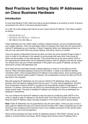
3Configuration Examples3.1Example for Static LAG3.1.1 Network RequirementsAs shown below, hosts and servers are connected to switch A and switch B, and heavytraffic is transmitted between the two switches. To achieve high speed and reliabilityof data transmission, users need to improve the bandwidth and redundancy of the linkbetween the two switches.Figure 3-1Network TopologyGi1/0/1Switch A.Gi1/0/8HostsGi1/0/1Gi1/0/8Switch BServers3.1.2 Configuration SchemeLAG function can bundle multiple physical ports into one logical interface to increasebandwidth and improve reliability. In this case we can configure static LAG to meet therequirement.The overview of the configuration is as follows:1) Considering there are multiple devices on each end, configure the load-balancingalgorithm as ‘SRC MAC DST MAC’.2) Add ports 1/0/1-8 to a static LAG.Demonstrated with T2600G-28TS, the following sections provide configuration procedurein two ways: using the GUI and using the CLI.3.1.3 Using the GUIThe configurations of switch A and switch B are similar. The following introductions takeswitch A as an example.1) Choose the menu L2 FEATURES Switching LAG LAG Table to load the followingpage. Select the hash algorithm as ‘SRC MAC DST MAC’.
Figure 3-2Global Configuration2) Choose the menu L2 FEATURES Switching LAG Static LAG to load the followingpage. Select LAG 1 and add ports 1/0/1-8 to LAG 1.Figure 3-33) ClickSystem Priority Configurationto save the settings.3.1.4 Using the CLIThe configurations of switch A and switch B are similar. The following introductions takeswitch A as an example.1) Configure the load-balancing algorithm as ort-channel load-balance src-dst-mac2) Add ports 1/0/1-8 to static LAG 1.Switch(config)#interface range gigabitEthernet 1/0/1-8Switch(config-if-range)#channel-group 1 mode onSwitch(config-if)#endSwitch#copy running-config startup-configVerify the ConfigurationSwitch#show etherchannel 1 summaryFlags: D - downI - stand-aloneP - bundled in port-channelU - in useH - hot-standby(LACP only)s - suspended
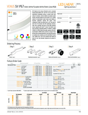
R - layer3S - layer2f - failed to allocate aggregatoru - unsuitable for bundlingw - waiting to be d - default portGi1/0/1(D) Gi1/0/2(D) Gi1/0/3(D) Gi1/0/4(D)Gi1/0/5(D) Gi1/0/6(D) Gi1/0/7(D) Gi1/0/8(D)3.2Example for LACP3.2.1 Network RequirementsAs shown below, hosts and servers are connected to switch A and switch B, and heavytraffic is transmitted between the two switches. To achieve high speed and reliabilityof data transmission, users need to improve the bandwidth and redundancy of the linkbetween the two switches.Figure 3-4Network TopologyGi1/0/1Switch A.Gi1/0/10Gi1/0/1Gi1/0/10Switch BHostsServers3.2.2 Configuration SchemeLAG function can bundle multiple physical ports into one logical interface to increasebandwidth and improve reliability. We can configure LACP to meet the requirement.The overview of the configuration is as follows:1) Considering there are multiple devices on each end, configure the load-balancingalgorithm as ‘SRC MAC DST MAC’.2) Specify the system priority for the switches. Here we choose switch A as the dominatedevice and specify a higher system priority for it.3) Add ports 1/0/1-10 to the LAG and set the mode as LACP.4) Specify a lower port priority for ports 1/0/9-10 to set them as the backup ports. Whenany of ports 1/0/1-8 is down, the backup ports will automatically be enabled to transmitdata.Demonstrated with T2600G-28TS, the following sections provide configuration procedurein two ways: using the GUI and using the CLI.
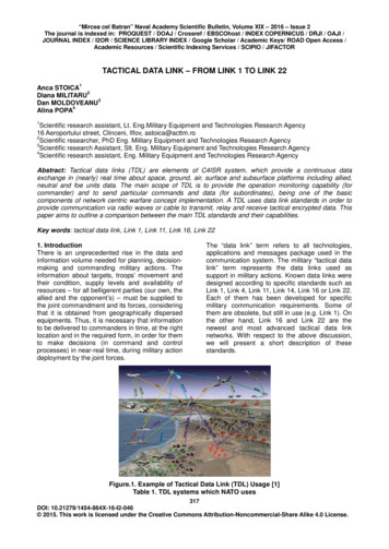
3.2.3 Using the GUIThe configurations of switch A and switch B are similar. The following introductions takeswitch A as an example.1) Choose the menu L2 FEATURES Switching LAG LAG Table to load the followingpage. Select the hash algorithm as ‘SRC MAC DST MAC’.Figure 3-5Global Configuration2) Choose the menu L2 FEATURES Switching LAG LACP Config to load thefollowing page. In the Global Config section, specify the system priority of Switch Aas 0 and Click Apply. Remember to ensure that the system priority value of Switch B isbigger than 0.Figure 3-6System Priority Configuration3) In the LACP Config section, select ports 1/0/1-10, and respectively set the status,group ID, port priority and mode for each port as follows.Figure 3-74) ClickLACP Configurationto save the settings.3.2.4 Using the CLIThe configurations of switch A and switch B are similar. The following introductions takeswitch A as an example.
1) Configure the load-balancing algorithm as ort-channel load-balance src-dst-mac2) Specify the system priority of Switch A as 0. Remember to ensure that the systempriority value of Switch B is bigger than 0.Switch(config)#lacp system-priority 03) Add ports 1/0/1-8 to LAG 1 and set the mode as LACP. Then specify the port priority as0 to make them active.Switch(config)#interface range gigabitEthernet 1/0/1-8Switch(config-if-range)#channel-group 1 mode activeSwitch(config-if-range)#lacp port-priority 0Switch(config-if-range)#exit4) Add port 1/0/9 to LAG 1 and set the mode as LACP. Then specify the port priorityas 1 to set it as a backup port. When any of the active ports is down, this port will bepreferentially selected to work as an active port.Switch(config)#interface gigabitEthernet 1/0/9Switch(config-if)#channel-group 1 mode activeSwitch(config-if)#lacp port-priority 1Switch(config-if)#exit5) Add port 1/0/10 to LAG 1 and set the mode as LACP. Then specify the port priority as 2to set it as a backup port. The priority of this port is lower than port 1/0/9.Switch(config)#interface gigabitEthernet 1/0/10Switch(config-if)#channel-group 1 mode activeSwitch(config-if)#lacp port-priority 2Switch(config-if)#endSwitch#copy running-config startup-configVerify the ConfigurationVerify the system priority:Switch#show lacp sys-id0, 000a.eb13.2397Verify the LACP configuration:Switch#show lacp internal
Flags: S - Device is requesting Slow LACPDUsF - Device is requesting Fast LACPDUsA - Device is in active modeP - Device is in passive modeChannel group 1PortFlags State LACP Port Priority Admin Key Oper Key Port Number Port StateGi1/0/1 SADown00x100x10x45Gi1/0/2 SADown00x100x20x45Gi1/0/3 SADown00x100x30x45Gi1/0/4 SADown00x100x40x45Gi1/0/5 SADown00x100x50x45Gi1/0/6 SADown00x100x60x45Gi1/0/7 SADown00x100x70x45Gi1/0/8 SADown00x100x80x45Gi1/0/9 SADown10x100x90x45Gi1/0/10 SA Down20x100xa0x45
4Appendix: Default ParametersDefault settings of Switching are listed in the following tables.Table 4-1Default Settings of LAGParameterDefault SettingLAG TableHash AlgorithmSRC MAC DST MACLACP ConfigSystem Priority32768Admin Key0Port Priority32768ModePassiveStatusDisable
The following example shows how to set the global load-balancing mode as src-dst-mac: Switch#configure Switch(config)#port-channel load-balance src-dst-mac Switch(config)#show etherchannel load-balance EtherChannel Load-Balancing Configuration: src-dst-mac EtherChannel Load-Balancing Addresses Used Per-Protocol: Non-IP: Source XOR Destination .