Transcription
Configuration Manager 7.40enUser manual
Configuration Manager 7.40Table of contents en3Table of contents1Introduction51.1About this manual51.2Conventions in this document51.3Additional documentation52System overview62.1Functions63Installation and starting73.1System requirements73.2Installation73.3Starting the program73.4Uninstalling the program74User interface94.1Overview94.2Main navigation bar tabs104.2.1The Remote Portal tab104.2.2The Network Scan tab114.2.3The My Devices tab114.2.4The Preferences tab114.3The Menu bar154.3.1The File menu154.3.2The Tools menu154.3.3The Help menu164.4Reload / Save icons174.5Toolbar icons174.6The Info bar184.7The Quick indication icons184.8The Status bar184.9The View pane194.10Used icons194.11Shortcut menu214.12Blocked input fields235Working with Configuration Manager255.1Adding devices to the system255.1.1Adding devices (for example, cameras, encoders)255.1.2Adding iSCSI devices255.2Allocating devices255.2.1Allocating listed devices265.2.2Allocating unlisted devices265.3Clearing device allocations275.4Creating groups275.5Defining a group as site285.6Accessing the device285.7Replacing devices295.8Defining storage locations305.9System emulation305.10Notes on multiple configuration315.11Configuring the toolbar section315.12Getting device information32Bosch Security Systems B.V.User manual2021.04 V8 DOC
4en Table of contentsConfiguration Manager 7.405.13Disabling network scan325.14Using the Table view325.15Importing .csv files355.16Using Device Health Monitor365.17Device configuration using the View pane375.18Managing certificates using MicroCA375.18.1Background information375.18.2Initializing the MicroCA385.18.3Configuring MicroCA using Smart Token385.18.4Configuring MicroCA using USB file405.18.5Signing device certificates425.18.6Managing user token455.18.7Creating user token465.18.8Configuring token-based device authentication475.19Finding/editing DSA E-Series devices475.19.1Finding DSA E-Series devices475.19.2Editing the port settings475.19.3Changing the password475.19.4Renaming the device475.20Connecting to the Bosch Remote Portal485.20.1Requesting access the Bosch Remote Portal application485.20.2Signing in to the Bosch Remote Portal application485.20.3Adding cameras to the Bosch Remote Portal application485.21App management for INTEOX cameras485.21.1Requesting access to the Security and Safety Things application store485.21.2Signing in to the Security and Safety Things application store495.21.3Checking the app status of the cameras495.21.4Downloading apps for installation in a local network495.21.5Installing downloaded apps locally and offline505.22Working with other components505.22.1Video Content Analysis505.22.2Monitor Wall51Index522021.04 V8 DOCUser manualBosch Security Systems B.V.
Configuration Manager 7.401Introduction1.1About this manualIntroduction en5This manual is intended for persons responsible for configuring and managing a CCTV system.This manual describes how to configure the program.This document assumes that the reader is familiar with both the CCTV system and the otherprograms that are integrated into the system.1.2Conventions in this documentThe symbols and notations that follow are used to draw attention to special situations:Notice!iThis symbol indicates special features and provides tips and information for easier, moreconvenient use of the software.Terms that you can find in the program, such as menu options, commands or text in the userinterface, are written in bold.1.3Additional documentationAfter the program has been installed, this document is also available as Help within theprogram.More informationFor more information, software downloads, and documentation, go towww.boschsecurity.com and the corresponding product page.Bosch Security Systems B.V.User manual2021.04 V8 DOC
6en System overview2Configuration Manager 7.40System overviewThe Configuration Manager program is used to configure all IP devices and components inyour CCTV network. With Configuration Manager you have access to all devices and softwarecomponents.2.1FunctionsConfiguration Manager provides the following functions (the availability of these depends onthe environment in which the program is used):–Network ScanThe network scan is performed automatically every time Configuration Manager starts,and is repeated at regular intervals.This function automatically detects all compatible devices present in a network, such ascameras or video senders, video receivers or VRM. The status of a device is also queriedin each scan and then indicated by the icons in front of the devices.–Device information and configurationComparable with the Web browser view, Configuration Manager shows the currentconfiguration for each device and allows you to change the settings.–Device system integrationYou use the Device allocator in Configuration Manager to make devices accessible for usewith Video Client.–MicroCAThe MicroCA functionality in the Configuration Manager program is an easy-to-use tinycertificate authority (CA) that facilitates the management of small to medium systems.–Multiple configurationYou can use Configuration Manager to make individual settings for multiple devicessimultaneously (for example, time settings), allowing you to configure large systems morequickly.–Simpler access to devicesThe Screenshot Scan function gives an overview of all the cameras that provide videodata. The screenshots can be used to identify the camera and device, and give you directaccess to said camera or device.–Table ViewThis allows you to compile specific parameter settings for selected devices. This providesyou with a quick overview of the settings that are of interest to you and allows you toexport this information for archiving at the push of a button.–Device Health MonitorThis provides you with a quick overview of the status of selected devices, such as theencoder load and type of network connection.–System emulationThe complete system configuration can be saved as a system image and emulated using adifferent Configuration Manager application. This function helps you to isolate problemswithout having to access the actual system.–Access to license managementFirmware modules requiring a license, such as IVA (Intelligent Video Analysis), are set upusing Configuration Manager.2021.04 V8 DOCUser manualBosch Security Systems B.V.
Configuration Manager 7.403Installation and starting en7Installation and startingThe Configuration Manager program is automatically part of the installation for all video IPdevices that require the Configuration Manager program for configuration purposes.Furthermore, you can also use the Configuration Manager program to simplify theconfiguration in a CCTV system with many similar video senders.3.1System requirementsNotice!i3.2All Microsoft updates and hotfixes must be installed on target PCs. Graphic card drivers mustalso have the latest officially released version described in the VideoSDK help.InstallationYou can install Configuration Manager on as many computers running Microsoft Windows asyou wish.Notice!iUsing multiple Configuration Manager programs in the network, maintaining the same or anoverlapping set of devices simultaneously can result in unpredictable effects when writing tothe devices.To install Configuration Manager:1.Download the software package.2.Close all other applications before starting the installation.3.Select the extraction directory, then double-click Setup ConfigManager.exe.The Configuration Manager wizard dialog box appears.4.On the Welcome dialog box, click Next.5.Follow the instructions on the screen.Note: We recommend using the default destination folder.6.3.3Click Finish.Starting the programAfter successful installation, you will find the Configuration Manager icon on your desktop:To start the program:4Double click the Configuration Manager icon.or4Click the Windows Start icon, then click Configuration Manager.Note:Several video IP devices enable you to start Configuration Manager directly within the relevantprogram.Operation of Configuration Manager varies according to the context in which it is being used.In some cases, it is merely a tool that enables you to configure video IP devices moreconveniently and more comprehensively. For certain programs and firmware modules,however, Configuration Manager is indispensable, as it is the only way to set these up.3.4Uninstalling the programIf you no longer wish to use the program on your computer, you can uninstall the program atany time.To uninstall the program:Bosch Security Systems B.V.User manual2021.04 V8 DOC
8en Installation and starting1.Configuration Manager 7.40Right-click the Windows start icon, then click Control Panel.The Control Panel window appears.2.On the Control Panel window, click the Uninstall a program link.The Programs and Features window appears.3.2021.04 V8 DOCIn the program list, right-click Configuration Manager, then click Uninstall/Change.User manualBosch Security Systems B.V.
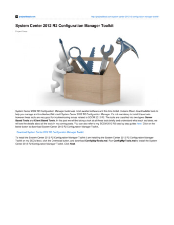
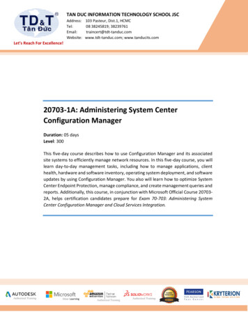
Configuration Manager 7.404User interface en9User interfaceIn this section, you will find detailed information about the user interface.4.1OverviewThe Configuration Manager program allows you to adapt the general appearance of the userinterface to your needs, for example, the display of the navigation bar on the left side or onthe top.Navigation bar to the left1Navigation bar2Device depending tabsThe displayed tabs depend on theselected device in the device treestructure.3Info bar4Quick indication bar5Expand navigation bar icon6Connect to Bosch Remote Portal7Expands the navigation bar and showsAllows you to connect to the Boschplain text beside the iconsRemote PortalMain navigation bar8Reload page / Save(Network Scan, My Devices,Preferences)Bosch Security Systems B.V.User manual2021.04 V8 DOC
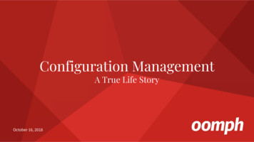
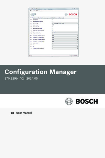
10en User interfaceConfiguration Manager 7.409Toolbar section (configurable)10For example: Info, Live video, TableDevice tree structure with filter andsearch optionView., Logging.11Menu bar (File, Tools, Help)13View pane12Status barThe display in the view pane dependson the selected device in the devicetree structure and the selected devicedepending tabs.Navigation bar on the top(numbering see table above)4.2Main navigation bar tabsThe navigation bar tabs allows quick access to the most important functions.4.2.1The Remote Portal tabThe Bosch Remote Portal application allows you to connect your devices securely to the BoschRemote Portal from anywhere without changes in the local network. Using the Bosch RemotePortal application you can then configure and maintain your devices remotely, and you cangive end-customers mobile access permission to devices.2021.04 V8 DOCUser manualBosch Security Systems B.V.
Configuration Manager 7.40User interface en11Refer to–4.2.2Connecting to the Bosch Remote Portal, page 48The Network Scan tabThe Network Scantab shows all video IP devices supported by the ConfigurationManager program that are detected in the network.Additional Information:–The information about a device is shown in bold if the device is newly detected since thelast network scan.–The information about a device is shown in red if the device has an IP address or a MACaddress that is already used by another device in the system. This might be the case, forexample, if several devices that have not yet been configured are connected directly afterone another.–4.2.3Additional information about the devices can be seen if you scroll to the right.The My Devices tabThe My Devicestab shows all devices that had been manually allocated to the system.Additional Information:–The information about a device is shown in bold if the device is newly detected since thelast network scan.–The information about a device is shown in red if the device has an IP address or a MACaddress that is already used by another device in the system. This might be the case, forexample, if several devices that have not yet been configured are connected directly afterone another.–4.2.4Additional information about the devices can be seen if you scroll to the right.The Preferences tabThe Preferencestab allows you to access general and application-specific settings.Here, you can carry out a basic configuration for Configuration Manager itself as well as forother video IP devices.This tab contains the following device depending tabs:–Access tab–Directories tab–Network tab–Video tab–Security tab–Logging tab–Appearance tabIf necessary, expand the folders to get subordinate items.Access tabThis tab contains the following groups:–Bosch Security Systems B.V.Access groupUser manual2021.04 V8 DOC
12en User interfaceConfiguration Manager 7.40Master passwordAssign a password here that protects access to the Configuration Manager program. Ifyou do not enter anything in this field, the program will start without asking for apassword.This password is only valid for the computer on which it was defined.Password policyWe recommend that you use strong passwords to enhance the protection of yourcomputer against unauthorized access.Saved credentialsDisplays your credentials (user, username, password).–Security groupEncrypt communication (defines the TLS connection preferences)To define the TLS connection preferences, select the required levels.–OptionalEncrypted connections (HTTPS) and non-encrypted connections (HTTP, RCP ) areallowed.No certificate validation is performed. The certificate requirement level is notrelevant.The default protocol HTTP is used when adding devices to the system.The VSDK security properties are set as follows: Allow unencrypted connections,Allow unencrypted media exports, and Allow no forward secrecy.–PreferredEncrypted connections (HTTPS) and non-encrypted connections (HTTP, RCP ) areallowed.The certificate validation is performed. The certificate requirement level is relevant. Ifvalidation failed a warning is displayed but a connection still possible.The default protocol HTTPS is used when adding devices to the system.The VSDK security properties are set as follows: Allow unencrypted connections,Allow unencrypted media exports, and Allow no forward secrecy.–RequiredA communication with devices is only possible using HTTPS.The certificate validation is performed. The certificate requirement level is relevant. Ifvalidation failed an error message is displayed and no connection is established.The default protocol HTTPS is used when adding devices to the system.There are no changes in the VSDK program.Certificate required levelTo validate certificates, select the required levels.–None: All certificates are accepted. No validation is performed.–Valid: Only an end certificate validation is performed. The certificate must be valid(standard validation procedure, time signature).–Trusted: The entire chain validation is performed, The root CA certificate is used tosign the certificate and must be trusted on machines where the validation isperformed.–Issued by the CA: The entire chain validation is performed, The root CA certificate isused to sign the certificate and the MicroCA program must be configured inConfiguration Manager program.–Environment Factors groupNetworkAllows you to select the kind of network (Dedicated network, Shared network, Internet).2021.04 V8 DOCUser manualBosch Security Systems B.V.
Configuration Manager 7.40–User interface en13Repository groupSeal configuration after backupAllows software sealing on the device after configuration has been backed up.Check seal integrityDoes an integrity check of the software seal on the device.Check settings integrityDoes an integrity check of the configuration of the device.Directories tabThis tab contains the following group:–Directories groupAllows you to select the folders guration repositoryNetwork tabThis tab contains the following groups:–Network Scan groupRun continuous network scanEnable this option if the network is to be scanned at regular intervals.Scan interval [s]Enter the time interval in seconds for automatic scanning here, choosing a value between10 and 3600 seconds (1 hour).–Network Scan RCP groupProtocollIn the Protocol list, click the protocol if you are using devices in various subnets.This allows all devices that belong to a different subnet than the PC on whichConfiguration Manager is installed to be included in the network scan. Otherwise you willhave to manually add these devices to the system.Multicast operation requires a multicast-enabled network that uses the UDP and theInternet Group Management IGMP protocols.Note: To get a valid multicast configuration, configure only RTP ports. The multicast portsmay only have even port numbers, while the ports with odd numbers may not be used.This is because the multicast protocols RTP and RTCP depend on each other. RTP usesthe even ports, while RTCP uses the next odd ports.–Bosch Remote Portal groupIn the URL box, enter the address of the Bosch Remote Portal. This allows you to connectthe Configuration Manager program to the Bosch Remote Portal page to perform remoteadministration and maintenance tasks.–IP address range groupModeIn the Mode list, click the mode (On, Off, Allow, Deny).In the From and To columns, enter the IP addresses, then select the protocol in theProtocol column.Video tabThis tab contains the following groups:–Bosch Security Systems B.V.Monitor groupUser manual2021.04 V8 DOC
14en User interfaceConfiguration Manager 7.40EncoderSelect whether the images should be displayed in video format (H.26x) or as constantlyupdated screenshots (JPEG).Refresh intervalSelect how often the screenshots that are shown in the various tabs (for example,Intelligent Video Analytics) are refreshed:Continuous: Image is refreshed as often as possible.0 seconds: Image is displayed once but not refreshed.1 10 seconds: Image is refreshed accordingly.–VCA groupShow default VCA live overlayif selected, the VCA overlays will be displayed on all video windows where applicable.Security tabThis tab contains the following groups:–MicroCA groupHere you can create a CA certificate.Create: Click Create. The Create CA dialog box is displayed.To create a CA certificate, refer to:Configuring MicroCA using Smart Token, page 38–Configuring MicroCA using USB file, page 40Load: Click Load. The Load CA dialog box is displayed. You can load existing CAcertificates.Signature Validity [days]: Select the validity of the certificate.User token groupCertificate store type: Click the Certificate store type list to display a list of existingtokens known to your system.To manage and create user tokens, refer to:–Managing user token, page 45–Creating user token, page 46––Logging tabThis tab contains the following groups:–Device I/O groupSelect the requird logs, for example, Log (read), Log (received), Log (message).–RCP logging groupEnable RCP loggingEnable or disable the logging of RCP commands. A log file is created for every device inthe system.Minimum numbersSpecify the maximum period for which you want the log data to be saved.–ONVIF logging groupEnable loggingEnable or disable the logging of ONVIF commands. A log file is created for every device inthe system containing the time stamp, the URL, the ONVIF service and the command. Theoutput is displayed in the Device Communication Log dialog box.–Miscellaneous groupWrite time stampSelect the check box to obtain the time stamps on the recordings.Appearance tabThis tab contains the following groups:2021.04 V8 DOCUser manualBosch Security Systems B.V.
Configuration Manager 7.40–User interface en15Language groupLanguageSelect the display language.Edit Toolbar:Click and adapt the toolbar to your needs.Config service enabledNot applicable–Startup groupRestore last viewIf selected, the last view is displayed when Configuration Manager is restarted.After confirmation onlyIf selected, the next time you start Configuration Manager you will be asked whether youwant to restore the last view.–Database camera name groupPrefix device name to camera nameDisplays the encoder device name before the camera name in the camera list if camerasare integrated into the system over video encoders.–Theme groupNavigation bar orientationSelect whether the navigation bar is displayed to the left or on the top.Refer to––––4.3Configuring MicroCA using Smart Token, page 38Configuring MicroCA using USB file, page 40Managing user token, page 45Creating user token, page 46The Menu barThis section describes special operational functions, tools and help functions.4.3.1The File menuTo get the File commands:4Click the Filemenu. The following commands are displayed.Emulate Alien System. / Abandon EmulationImports the system image of an alien Configuration Manager system.Export VDBAllows you to export the database with the user defined password.CloseCloses the Configuration Manager program. This also breaks the connection betweenConfiguration Manager and the server.4.3.2The Tools menuTo get the Tools commands:Bosch Security Systems B.V.User manual2021.04 V8 DOC
16en User interface4Configuration Manager 7.40Click the Toolsmenu. The following commands are displayed.Logging.Displays the Device Communication Log dialog box.Here, you can view the RCP commands that are transmitted by Configuration Manager whenconnecting to devices, if you have enabled logging.Device Allocator.Displays the Device Allocator dialog box containing an overview of all available devices in thenetwork and all devices that are allocated to the system.Snapshot ScanDisplays a dialog box containing a snapshot for each of the selected cameras. If you right-clicka snapshot, the commands are displayed relevant for the camera.Device Health Monitor.Displays the Device Health Monitor dialog box, that provides a quick overview of the status ofselected devices.Save System ImageSaves the image of the current Configuration Manager system for emulation on a different PC.Import .csv File Displays a dialog box that allows you to import .csv files.Import Project Assistant FileDisplays the Project Assistant Import dialog box where you can select the files to be imported.Security and Safety Things Store4.3.3The Help menuTo get the Help commands:4Click the Helpmenu. The following commands are displayed.Online Help.Displays the Configuration Manager Help.Online Help VRM.Displays the Video Recording Manager Help.Online Help IVA.Displays the Intelligent Video Analytics Help.2021.04 V8 DOCUser manualBosch Security Systems B.V.
Configuration Manager 7.40User interface en17About.Displays the About Configuration Manager dialog box, containing information on, forexample, the software components installed on this PC and the software version numbers ofthe installed components.4.4Reload / Save iconsReload pageReloads device and page information and starts a device scan on the Devices tab.SaveSaves any settings that have been configured for the selected device.4.5Toolbar iconsThese icons allow quick access to several Configuration Manager functions.InfoDisplays detailed information about the selected device.Live videoDisplays the live video data from the selected device.Configuration repository,,,Display the Configuration repository dialog box showing device configuration information, forexample; device count notes, firware and hardware versions.Table viewDisplays the Table View dialog box containing the devices in table view.Click again to close the Table View window.Logging.Displays the Device Communication Log dialog box.Here, you can view the RCP commands that are transmitted by Configuration Manager whenconnecting to devices, if you have enabled logging.Device Allocator.Displays the Device Allocator dialog box containing an overview of all available devices in thenetwork and all devices that are allocated to the system.Import .csv File Displays a dialog box that allows you to import .csv files.Bosch Security Systems B.V.User manual2021.04 V8 DOC
18en User interfaceConfiguration Manager 7.40Device Health Monitor.Displays the Device Health Monitor dialog box, that provides a quick overview of the status ofselected devices.Save System ImageSaves the image of the current Configuration Manager system for emulation on a different PC.Snapshot ScanDisplays a dialog box containing a snapshot for each of the selected cameras. If you right-clicka snapshot, the commands are displayed relevant for the camera.Import Project Assistant FileDisplays the Project Assistant Import dialog box where you can select the files to be imported.4.6The Info barIf a device is selected under the Network Scan or My Devices tabs, an info bar is displayed tothe right of the top navigation pane. This info bar provides you with brief information abouteach selected device as follows:–Device type–Device IP addressNotice!i4.7The info bar is only available if the navigation bar is on the top.The Quick indication iconsTo display the quick indication icons:4Drag the pointer on the icons to view details on the processor load, network connectionand recording status:Quick indication icon description–The left icon indicates the proportions of the individual functions on the encoder load,shown as percentages. For devices with two processors, a separate icon is shown foreach processor.–The icon in the middle indicates the network connection type and the speed of theoutgoing (UL Uplink) and incoming (DL Downlink) data traffic.–4.8The right icon indicates information on the recording status.–Green: active recording–Red: error–Orange: recording scheduler active, no current recordings–Gray: recording scheduler not active, no current recordingsThe Status barThe status bar at the bottom edge of the window shows the following:–2021.04 V8 DOCIn the central section: the number of detected, visible and selected devices.User manualBosch Security Systems B.V.
Configuration Manager 7.40–User interface en19In the central section: whether you are currently working Online, and whether or notConfiguration Manager is currently connected to a server. If it is connected to a server,the server IP address is displayed. Otherwise the entry DB local appears here.If you are emulating an alien system, the entry System emulation appears here.–4.9On the far right: the version number of Configuration Manager is displayed.The View paneThe View pane for the Network Scan and My Devices tabs shows a series of subdivided tabs,the number and content of which depend on the device selected in the list.The tabs in the View pane can be used to make the configuration settings that the device alsoprovides in the Web browser view, some of them with a slightly different composition.Access from Configuration Manager to the devices can be configured when selecting theGeneral and Unit Access tab (not necessary for web browser).Detailed information about the configuration options for a device can be found in the relevantdevice documentation and the online Help in the relevant Web browser view.Notice!i4.10Changes only become active if you click the Save tab.Used iconsThe devices in the Network Scan or My Devices tabs are represented by the following icons:Device iconsCameraDevice (for example, Encoder/Decoder/StreamingGateway)Hardware recorder (for example, DIVAR)Storage system (for example, DIVAR)DomeCameraiSCSI targetVideo Recording Manager serverVideo Recording Manager failover serverVideo Recording Manager server for secondrecording streamVideo Recording Manager failover server for secondrecording streamUnknownDevice status iconsThe status of the icons is shown exemplarily by using a camera. Other devices are displayed inthe same mannerBosch Security Systems B.V.User manual2021.04 V8 DOC
20en User interfaceConfiguration Manager edconnectioncertficatesCamera greyOKNoUnknownUnknownUnknownCamera grey,Warning *NoUnknownUnknownUnknownError *NoUnknownUnknownUnknownNo accessNoNo *UnknownUnknownOKYesYesNoexclamation markyellowCamera grey,exclamation markredCamera grey,lock redCamera blueNotrelevantCamera blue,WarningYesAnyNoexclamation markNotrelevantyellowCamera blue,ErrorYesAnyNoexclamation markNotrelevantredCamera blue,No accessYesNoNolock redNotrelevantCamera yellowOKYesYesYesNoCamera yellow,WarningYesAnyYesNoErrorYesAnyYesNoNo accessYesNoYesNoCamera greenOKYesYesYesYesCamera green,WarningYesAnyYesYesErrorYesAnyYesYesNo accessYesNoYesYesexclamation markyellowCamera yellow,exclamation markredCamera yellow,lock redexclamation markyellowCamera Green,exclamation markredCamera green,lock red* Device was online2021.04 V8 DOCUser manualBosch Security Systems B.V.
Configuration Manager 7.40User interface en21Icons on the View paneThe following icons are used on the View pane:Help. Click the icon to open context-related help.Warning. This element contains important information.Danger. This element contains very important information.Info. Click the icon to display a camera's properties.Connection established.Connection lost.Recording state: Device is recording.Recording state: Device is not recording.Relay state: Relay is in default state.Relay state: Relay switched to alert state.Locked: This element does not allow input or changes.MicroCA iconsThe following icons are related to the MicroCA functions:Certificate icon: Shows the certificate status.Signing icon: Click this icon to sign and upload a certificate.User token icon: Click this icon to add a user token.4.11Shortcut menuRight-click a device to open the shortcut menu. If you have selected multiple devices, not alloptions in the shortcut menu are enabled.The following provides an overview of the commands:Select Group(My Devices tab)If several devices have been grouped, use this command to select all devices or cameras ofthat group for editing.Node Expand Child Nodes(My Devices)Click to expand a group or site to see the devices and cameras assigned to it.Node
The Configuration Manager program is automatically part of the installation for all video IP devices that require the Configuration Manager program for configuration purposes. Furthermore, you can also use the Configuration Manager program to simplify the configuration in a CCTV system with many similar video senders. 3.1 System requirements i .