Transcription
Configuration Manager970.129b V2 2014.05en User Manual
Configuration ManagerTable of Contents en3Table of tallation53General commands63.1Language63.2Create a new BPA file63.3Revert to factory settings63.4Print63.5Export to CSV73.6Set date and time73.7Exit74Programming via microSD card / hard disk drive84.1Installing the microSD memory card84.2Programming procedure via microSD card / hard disk drive105Programming via serial connection115.1Serial connection115.2Getting started115.3Programming procedure via serial connection125.4Firmware reflash125.5Manual firmware reflash145.6How to do with older Carephones156Programming steps16AAppendix33A.1Technical specifications33A.2APN codes34Bosch Security SystemsUser Manual970.129b V2 2014.05
4en Description1Description1.1FeaturesConfiguration ManagerThe Configuration Manager is a standalone software for–reading/writing the device parameters of BoschCarephones 6X via serial connection, microSD card or harddisk drive–updating the firmware of Bosch Carephones 6X via serialconnection.NOTICE!The programming via serial connection is supported at BoschCarephones 6X from:1.2–Bosch Carephone 61 A2.02–Bosch Carephone 62 A0.07FunctionsThe following information can be edited:–Call targets, protocols and media type–General configuration, such as radio transmissionmonitoring, activity monitor parameters, etc.–Extended configuration, such as waiting time for repeatedemergency calls, activation of service button, etc.–Function assignment, which allows assigning a call numberto each individual call trigger.–IP/GSM configuration, related to IP and GSM features–RF detector programming data, allowing assigning a calltrigger to the wireless detectors.The settings can be saved into a CSV file, facilitating the uploadof these settings into other applications. The settings can alsobe printed.microSD is a trademark of SD-3C, LLC.970.129b V2 2014.05User ManualBosch Security Systems
Configuration Manager2Installation en5InstallationDownload the MSI file package from www.boschsecurity.com.Store the file on your computer, double-click it and follow thesteps of the setup wizard.Bosch Security SystemsUser Manual970.129b V2 2014.05
6en General commandsConfiguration Manager3General commands3.1Language Select the language in which you wish to see theConfiguration Manager: click on Settings then Language.3.2Create a new BPA file Select File and New, a new BPA file for Carephones will becreated. You can temporarily name it as you wish, but assoon as you want to upload it to a Carephone, you mustname it settings.bpa. 3.3In the menu Settings, Select the Carephone type.Revert to factory settings Select File and Factory settings, all the parameters in theConfiguration Manager are reverted to the factory settingsof the Carephone type.3.4Print Select File and Print, all the parameters in theConfiguration Manager are sent to your default printer.970.129b V2 2014.05User ManualBosch Security Systems
Configuration Manager3.5General commands en7Export to CSV Select File and Export to CSV, all the parameters in theConfiguration Manager are exported to a CSV file.3.6Set date and timeOnce the serial connection is established between theCarephone and the Configuration Manager, you can set the dateand time values. The Configuration Manager will take thecurrent date and time of the computer running it.1.In the menu Serial, select Set date and time.2.The Configuration Manager updates the date and time intothe Carephone, and displays a confirmation message:NOTICE!A reset, disconnecting the main power supply or disconnectingthe battery power, will erase the date and time.3.7Exit Select File and Exit, the Configuration Manager will close.If you have not saved your changes, a warning will appear.Bosch Security SystemsUser Manual970.129b V2 2014.05
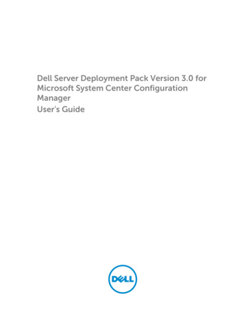
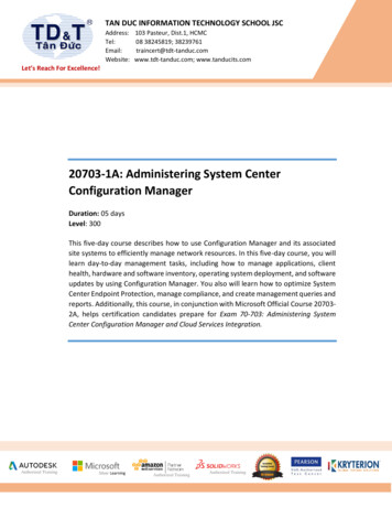
8en Programming via microSD card / hard disk drive4Configuration ManagerProgramming via microSD card /hard disk driveNOTICE!Before you program the Carephone 61/62, you must be familiarwith all of the unit's functions. Programming is specificallyintended for trained users. Correct programming of theCarephone 61/62 is important for the full function of the unit.Make sure to always read the existing configuration beforechanging the values of the programming steps.4.1Installing the microSD memory cardThe Carephone 61/62 can be equipped with a microSD memorycard to perform a fast and easy programming.NOTICE!Use a microSD memory card of 32 GB capacity or lower.1.Remove the plug of the power supply unit from the socket2.Open the top cover of the unit to access to the connectionon the Carephone 61/62.compartment. The location of the microSD port isindicated in the following diagram:970.129b V2 2014.05User ManualBosch Security Systems
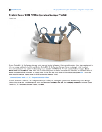
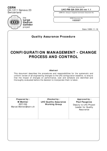
Configuration Manager3.Programming via microSD card / hard disk drive en9Take the microSD memory card in the hand and place itwith the contacts facing you, as on the drawing.4.Insert the microSD memory card in the slot and push ituntil you feel the mechanism has clutched it.5.Insert the plug of the power supply unit from the socket onthe Carephone 61/62.6.Perform the programming action that you wish. SeeSection 4.2 Programming procedure via microSD card / harddisk drive, page 10.7.When you are finished and wish to remove the microSDmemory card, remove the plug of the power supply unitfrom the socket on the Carephone 61/62.8.To disengage it from the slot, simply push on the end ofthe microSD memory card and gently pull it out.Bosch Security SystemsUser Manual970.129b V2 2014.05
10en Programming via microSD card / hard disk drive4.2Configuration ManagerProgramming procedure via microSD card/ hard disk driveNOTICE!Before reading from the microSD memory card, make sure thatit contains a file. Before writing to the microSD memory card,make sure that it is not write-protected. Existing files with samenames will be overwritten.Step 1: open the BPA setting file of the Carephone In the menu File, select Open to open the correspondingparameter file from the microSD card or from the hard diskdrive.Based on the BPA setting file, the Configuration Manageridentifies and displays the Carephone type in the lower rightcorner of the window. In this case, you cannot change thesetting Carephone type.Step 2: program the parameters of the CarephoneChange the parameters for the Carephone. Refer toSection 6 Programming steps, page 16.Step 3: save the parameters to the microSD card or hard diskdrive When you are finished programming, select Save to savethe BPA setting file to the microSD card or to the hard diskdrive. The file name must always be settings.bpa. If youchange the name of the file, then the upload of theparameter update into the Carephone will malfunction.970.129b V2 2014.05User ManualBosch Security Systems
Configuration ManagerProgramming via serial connection en5Programming via serial connection5.1Serial connection11The programming via serial connection is supported at BoschCarephones 6X from:–Bosch Carephone 61 A2.02–Bosch Carephone 62 A0.07For Bosch Carephones 6X that do not support programming viaserial connection, the commands Read Parameters and WriteParameters are disabled. You will also get an error messageinviting you to update the Carephone. See Section 5.6 How to dowith older Carephones, page 15.5.2Getting startedEstablish the serial connection In the menu Settings, select the COM Port to be used. Connect the Carephone 6X to its power supply. Connect the Carephone 6X to the computer running theConfiguration Manager.–Use the Bosch serial programming cable APD 9 poles(commercial type number CRS-CP-SPC-APD9P, SAPnumber F.01U.140.074). If needed, the USB to serialadapter Brainboxes model US-101 can be recommended.The Configuration Manager now detects the Carephone anddisplays the information related: version and build, as well asthe Carephone type in the lower right corner of the window.In this case, you cannot change the setting Carephone type.Bosch Security SystemsUser Manual970.129b V2 2014.05
12en Programming via serial connection5.3Configuration ManagerProgramming procedure via serialconnectionOnce the Carephone is connected to its power supply and tothe computer running the Configuration Manager via the serialcable, you can start programming directly the Carephone.Step 1: read the parameters from the Carephone In the menu Serial, click on Read Parameters.The Configuration Manager reads all the parameters from theCarephone and displays them in the different tabs.Step 2: program the parameters of the CarephoneChange the parameters for the Carephone.Refer to Section 6 Programming steps, page 16.Step 3: write the parameters to the Carephone When you are finished programming, click on WriteParameters. The parameters are now sent to theCarephone via serial connection.5.4Firmware reflashThe Configuration Manager must first detect the Carephoneand display the version and build. See Section 5.2 Gettingstarted, page 11.Step 1: launch the firmware reflash interface In the menu Serial, select Firmware reflash.970.129b V2 2014.05User ManualBosch Security Systems
Configuration ManagerProgramming via serial connection en13The Carephone 6X Reflash interface opens:Step 2: select the firmware file Click on the browse button and select the Motorola S19firmware file. Make sure that the firmware file correspondsto the type of Carephone 6X that you are about to reflash.You have the possibility to keep the user audio announcementmessage. If so, tick the check-box.Step 3: start the firmware reflash Click on Reflash on the Carephone 6X Reflash interface.The firmware is sent to the Carephone:Bosch Security SystemsUser Manual970.129b V2 2014.05
14en Programming via serial connectionConfiguration ManagerCAUTION!Do not disconnect the Carephone until the firmware update isfinished!5.5Manual firmware reflashIf the firmware reflash was interrupted, you must proceed witha manual firmware reflash.Step 1: launch the manual firmware reflash interface In the menu Serial, select Manual firmware reflash.The Manual Firmware Reflash interface opens:CAUTION!Make sure that the Carephone is connected to its power supplyand to the computer running the Configuration Manager via theserial cable. Do not disconnect it until the manual firmwarereflash is finished!970.129b V2 2014.05User ManualBosch Security Systems
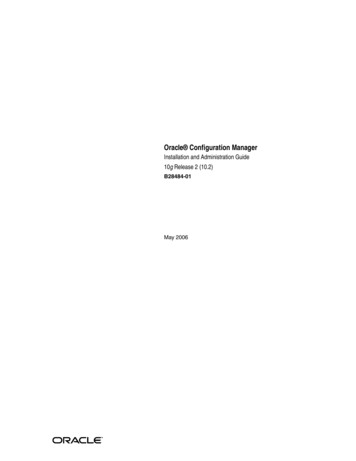
Configuration ManagerProgramming via serial connection en15Step 2: bridge the Carephone 6X Open the Carephone 6X that needs a manual firmwarereflash, as when replacing the battery.Refer to the user manual of the Carephone 6X. Connect the bridge, using a small slotted screwdriver:Step 3: start the manual firmware reflash Click on Connect on the Manual Carephone 6X Reflashinterface.The Carephone is now reconnected to the ConfigurationManager. The Carephone 6X Reflash interface opens. To finishreflashing the firmware, proceed as in Section Step 2: select thefirmware file, page 13.5.6How to do with older CarephonesFirmware updateBefore starting to program a Carephone that does not supportprogramming via serial connection, you must first make afirmware update to get:–for a Bosch Carephone 61: version A2.02 or newer–for a Bosch Carephone 62: version A0.07 or newerProceed as in Section 5.4 Firmware reflash, page 12.Bosch Security SystemsUser Manual970.129b V2 2014.05
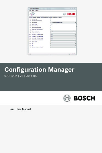
166en Programming stepsConfiguration ManagerProgramming stepsProgramming a Carephone 61/62 with the ConfigurationManager consists of entering values for the individual steps,numbered 01 to 129.NOTICE!According to the Carephone type, programming steps may notbe visible and their values may change.Tab 1 "General"970.129b V2 2014.05User ManualBosch Security Systems
Configuration ManagerProgramming steps en1703. Radio jammingThe Carephone 61/62 sends a technical message to the monitoring centrewhen a radio signal from another device disturbs it. Check the tick-box toenable this function.25. Radio transmission monitoringThe Carephone 61/62 can monitor the wireless transmitters that areassigned. The wireless transmitters send a signal to the Carephone 61/62at regular intervals. A failure message is sent to the monitoring centre ifthe Carephone 61/62 does not receive this signal at least once a week.Check the tick-box to enable this function.28. Call forwardingIt is possible for the monitoring centre, if it supports this functionality, tocommand the Carephone 61/62 to forward the current call to a newdestination using a specified protocol. You can allow the Carephone 61/62to use the specified protocol or force it to use telephone protocol. Thisfunction is only possible with protocols RB2000E (target 0), CPC (target 3)and RBIP (target 9). Choose between:–0 forwarding to another number, 1 forwarding to a telephone.30. Device numberWhen an emergency call is made, this number is sent to the monitoringcentre. The number can be up to 12 digits long. Numbers 0000, 9998, 9999and 999999 may not be used. Default value is 1248.31. Sign in / sign outTo specify whether the sign in or sign out of the activity monitor willinitiate a call to a call recipient. Check the tick-box to enable this function.32. Call progress tones audibleYou can choose to hear the call progress tones when the Carephone makesa call. Check the tick-box to enable this function.Bosch Security SystemsUser Manual970.129b V2 2014.05
18en Programming stepsConfiguration Manager33. Speak / Listen command audibleYou can choose to hear the commands when the Carephone switchesbetween speak and listen in half-duplex mode. Check the tick-box toenable this function.40. Activity monitor hours and minutesThe time for the activity monitor can be set between 15 minutes and 31hours in steps of 15 minutes.–Enter the number of hours (example: 24 for 24 hours) in the first field.–Enter the number of minutes: 0 for 0 min, 1 for 15 min, 2 for 30 minand 3 for 45 min. It is also possible to program an automaticactivation of the sign-out status. To activate the special feature forpassive alarms, enter 4 for 0 min, 5 for 15 min, 6 for 30 min and 7 for45 min. In this case, any intrusion alarm will be silent.Programming 0 - off and 0 (0 hours and 0 minutes) deactivates the activitymonitor. Programming 99 means the time frame is set by the monitoringcentre or through an SD card. This can only be used if the unit getsregularly real-time clock updates from a monitoring center.100. Scheduler for the activity monitorYou set up a scheduler for the activity monitor, with 2 time slots duringwhich the activity monitor is active. Select, in 15 minutes intervals:start time 1, end time 1, start time 2 and end time 2.62. Loudspeaker volume (Default, Max, Min)This step is used to program the default volume as well as the maximumand minimum settings. The default volume is the volume at which themonitoring centre communicates via the Carephone 61/62.Maximum setting is high volume. Minimum setting is low volume.Choose a value between 1 to 8 to program these three volumes.Default values are 4, 6 and 2 are shown first.70. Automatic test call intervalYou can program the interval between automatic test calls from theCarephone 61/62 to the monitoring centre in days. In addition, there is atest call after power up or leaving programming mode, as well as a test callper randomization. Select from 1 to 28 days, 0 off970.129b V2 2014.05User ManualBosch Security Systems
Configuration ManagerProgramming steps en19Tab 2 "Call Targets"Bosch Security SystemsUser Manual970.129b V2 2014.05
20en Programming stepsConfiguration Manager11- 19 & 10 Destination number of the emergency call recipientYou can enter here the destination number of the emergency call recipient,either a telephone number, or an IP address.1) Enter the destination number of the emergency call recipient.In the case of a telephone number, register the call number as follows:You can add the following criteria in a telephone call number:B Dial pause, D Dial tone detection.In the case of an IP address, the call number should be written in numberswithout dots, always 12 digits. Example: 192168010001.2) After entering the call number, you must enter the protocol:–0 monitoring centre (protocols RB2000, RB2000E, ANT)–1 monitoring centre (TTnew protocol)–3 monitoring centre (CPC protocol)–4 to phone with acknowledgement–5 to phone without acknowledgement (only for direct call)–7 monitoring centre (BS8521 protocol)–9 monitoring centre (RBIP protocol)Settings 0 to 7 are designed to be used with the media PSTN.Setting 9 is designed to be used with the IP Module or GSM Module.3) After entering the protocol, you can enter the media:–0 PSTN, related to the analogue interface of the Carephone.This also applies with a GSM Gateway or a DSL/cable modem.–1 LAN, related to the IP Module–2 GSM, related to the GSM ModuleThe Carephone goes automatically to the next programming step and youcan enter the next call number. When an emergency call is sent and if thecall to the first call number is not successful, the Carephone will try thenext numbers in the sequence 11 to 10. If the last number has been dialedunsuccessfully, the unit starts with the first number again and continuesuntil it sends an emergency call successfully. A single programmedtelephone number will be tried 12 times. The maximum number of dialattempts can be set. By default, it is set to 15 attempts.970.129b V2 2014.05User ManualBosch Security Systems
Configuration ManagerProgramming steps en21Tab 3 "Extended"23. Waiting time for repeated emergency callAn emergency call is repeated to check the arrival of staff until it isacknowledged by pressing the Action button on the Carephone 61/62, orthe repeated call is disabled by the monitoring centre. The emergency callis repeated when the defined waiting time is exceeded.–Enter a time between 0 and 99 minutes. 0 off. Default value is 0.Bosch Security SystemsUser Manual970.129b V2 2014.05
22en Programming stepsConfiguration Manager26. Callback waiting timeThe callback function enables the help provider or monitoring centre toterminate an alarm after having acknowledged it. The Carephone must becalled back, or the Action button must be pressed, after an alarm has beenacknowledged. Define the waiting time after the acknowledgement, duringwhich a call back will be accepted. If this call back waiting time haselapsed, then a new call will be sent by the Carephone.–Enter a time between 0 and 9 minutes. 0 off. Default value is 0.60. Number of announcements when calling a telephoneSpecify how often the Carephone will announce the recorded message.–0 no announcement, from 1 to 9 for the required number ofannouncements. Default value is 2.61. Incoming call recognitionIncoming phone calls can be accepted and terminated by the Carephone61/62’s emergency call button or by using the wireless transmitter if it isprogrammed for emergency call initiation. The ring tone on the Carephone61/62 can be switched on or off and the volume can be adjusted.–0 off (no incoming call can be answered and terminated by thewireless transmitter or call button)–1 with ring tone–2 with loud ring tone–3 with soft ring tone–4 without ring tone (only the phone rings)–Default value is 0.71. Action button (S button)The Action button can be configured differently according to your needs:–0 off–1 service button / direct call (e.g. service call to a monitoring centreor direct call to a relative)–3 activate relay output (e.g. a door opener)–Default value is 0.970.129b V2 2014.05User ManualBosch Security Systems
Configuration ManagerProgramming steps en2372. Activate outputThe Carephone 61/62 provides a potential-free relay output with anormally open switch contact. Program the way the output reacts:–0 off–1 speak / listen connection and repeated emergency call–3 outgoing emergency call–4 incoming call recognition–5 wireless transmitter–6 remote activation–7 speak / listen connection–8 pre-alarm–9 pre-alarm and speak / listen connection–Default value is 0.73. Assign inputThe Carephone 61/62 provides external inputs. The function assigned canbe programmed:–0 external activity monitor reset–1 emergency call button–2 service call–3 external input–9 fire alarm–B motion detection–Default value is 3 - External input.73. Input isAfter assigning the input, the input can be chosen as a:–0 normally open contact (closing)–1 normally closed contact (opening)75. Individual PIN codeThe Carephone 61/62 is delivered with the factory setting 246810 for thePIN code. It is recommended not to change this code. If you need tochange this code, take care to write it down to find it easily. The PIN codeis reset when resetting the unit to its factory settings.Bosch Security SystemsUser Manual970.129b V2 2014.05
24en Programming stepsConfiguration Manager63. Acoustical feedback for technical failuresThe Carephone 61/62 can be set to announce technical failures throughthe LED lamps and the loudspeaker, or through the LED lamps only.–0 loudspeaker off–1 loudspeaker on. This is the default value.–2 loudspeaker on from 7:00 to 21:00–3 an acoustical failure indication (message or beep) is repeated witha pause of 10 seconds until the Action button is pressed.–4 an acoustical failure indication (message or beep) is repeatedduring day time (from 7:00 to 21:00) with a pause of 10 seconds untilthe Action button is pressed.Settings 2 and 4 are only available if the time and date are set. This can bedone through keyboard programming, Configuration Manager with serialserial connection or via a remote date/time update from a receiver.77. Pre-alarm timeThe pre-alarm time of the Carephone 61/62 can be programmed. This isthe time frame in which an emergency call can still be stopped.–Select a setting, in steps of 10 seconds, between 0 and 6.–0 off, 1 10 s, 2 20 s, etc. Default value is 1.24. Confirmation with callWhen the repeated emergency call has been locally acknowledged, you canspeak directly to the monitoring centre.27. Presence marking - Service doneThe presence marking function allows staff members to mark theirpresence or signal that the service is done by pressing the daily button.This is handled without a speak/listen connection and does not require ananswer by the operator. When the presence marking is activated, thedestination numbers to be called are set in the call sequence of step 58 ofthe tab Function assignment. This function resets the activity monitor,which must be set. See step 40 of the tab General.02. CPC AdaptationYou can set the Carephone 61/62 to use a specific CPC adaptation whenthe CPC protocol is used. Check the tick-box to enable this function.970.129b V2 2014.05User ManualBosch Security Systems
Configuration ManagerProgramming steps en25Tab 4 "Function assignement"Bosch Security SystemsUser Manual970.129b V2 2014.05
26en Programming stepsConfiguration ManagerFunction assignmentIt is possible to link an alarm type to specific call numbers. Eachprogramming step refers to a certain alarm type.–50. Wireless Transmitter (emergency call with a wireless transmitter)–51. Emergency call (with the Carephone 61/62)–52. Fire / intrusion–53. Repeated emergency call and local confirmation–54. Sign in / sign out–55. Service call / direct call. The direct call can only made to atelephone without acknowledgement. A single attempt will be made.–56. Technical messages 1 (power failure, power restored, unit batteryfailure, unit battery low, line failure, line restored)–57. Technical messages 2 (automatic test call, radio jamming, radiotransmission monitoring, transmitter battery low)Choose which destination numbers 1 to 10 are associated with each alarmtype (call sequence). If no destination number is entered, then allprogrammed call numbers will be called. It is not possible to have thesame destination number twice.–58. Registration call / presence marking - service doneRegistration call: after an emergency call, the destination numberentered in setting 58 will be called for registration purposes. The calldestination must be a monitoring centre.Presence marking - service done: see step 27.Choose which call numbers 1 to 10 are associated with this alarm type(call sequence). If no destination number is entered, then no call is made.It is not possible to have the same destination number twice.970.129b V2 2014.05User ManualBosch Security Systems
Configuration ManagerProgramming steps en27Tab 5 "IP/GSM"41. DHCP (IP Module)Enable or disable the Carephone 61/62 to use a DHCP service. Check thetick-box to enable this function.42. IP Address (IP Module)Enter here the IP address of the Carephone 61/62. It should be written innumbers without dots, always with 12 digits.The factory setting is: 192168001100.43. IP subnet mask (IP Module)Enter here the IP subnet mask of the Carephone 61/62. It should bewritten in numbers without dots, always with 12 digits.The factory setting is: 255255255000.Bosch Security SystemsUser Manual970.129b V2 2014.05
28en Programming stepsConfiguration Manager44. Gateway (IP Module)Enter here the IP address of the network gateway in case the Carephone61/62 is connected through this type of device. It should be written innumbers without dots, always with 12 digits.The factory setting is: 192168001001.45 Automatic test call hours (IP/GSM Module)Program the interval between automatic test calls of the IP Module or GSMModule from the Carephone 62/61 to the monitoring centre in hours.Select from 1 to 999 hours, 0 off, factory setting 1049 Phone number of GSM Module (without country code)Program the own phone number for the GSM Module to be used for theCarephone 62/61. Maximum length is 22 digits. If the country code of thephone number of alarm receiving center and GSM module is the same,then it must not be part of the phone number. If the country code isdifferent, then it must be part of the phone number.47 SIM card PIN Code (GSM Module)Program the SIM PIN Code for the GSM Module. Max. length is 8 digits.48 APN Code (GSM Module)Program the code for the Access Point Name (APN) between 0 and 99.The default setting is 0.The APN codes can be found at Section A.2 APN codes, Page 34.48 Auto provider selection (GSM Module)Use this option if you wish to activate or deactivate the automaticselection of the GPRS provider. This is useful to avoid unwanted roamingcosts. Check the tick-box to enable this function.NOTICE!Programming steps 42, 43 and 44 are not used when a DHCPservice is enabled (setting in step 41). In DHCP mode, the IPaddress, subnet mask and gateway address are allautomatically requested from the local DHCP server.970.129b V2 2014.05User ManualBosch Security Systems
Configuration ManagerProgramming steps en29Tab 6 "Professional"01. Language selectionChoose between different languages: 1 German, 2 Dutch, 3 French,4 English, 5 Spanish, 0 is for the synthetic speech disabled mode.29. Hear/speech impairedThis is dedicated to users with speaking or hearing difficulties. Once aconnection to the monitoring centre is established, the signals advise theuser that he or she is through to the monitoring centre (the centre islistening). If the user presses the emergency call button, the messageemergency call is sent to the monitoring centre. If the stop button ispressed, then the recorded message (e.g. "everything is okay") is sent.Check the tick-box to enable this function.74. Silent alarmThe Carephone 61/62 can send silent alarms. When this is activated, theloudspeaker of the Carephone 61/62 is turned off. Only the microphoneremains active. Check the tick-box to enable this function.Bosch Security SystemsUser Manual970.129b V2 2014.05
30en Programming stepsConfiguration ManagerTab 7 "RF detector"970.129b V2 2014.05User ManualBosch Security Systems
Configuration ManagerProgramming steps en31RF detector registering and assigning:Enter the code number for each transmitter (91, 92, etc.)Assign a function to each wireless transmitter (81, 82, etc):–0 - emergency call with a wireless transmitter–1 - emergency call with the Carephone 61/62–2 - activity monitor reset with unit feedback–3 - sign in / sign out–4 - action button–5 - external input–6 - activity monitor reset without unit feedback–7 - connection to an individual phone number value, thenassign the call numbers 1 to 10 to be associated with thisalarm function.–8 - output assigned–9 - fire alarm–B - motion detection–D - extended programmingIf you have selected D in steps 81, 82, etc, you can choose theextended transmitter type (111, 112, etc):–Panic alarm–Bogus call alarm–Stove alarm–Fall detector–Bed alarm–Gas alarm–CO alarm–Contact detector alarm–Temperature alarm–Flood detector alarm–Pull switch alarm–Use the custom alarm type and event handler. See steps201, 202, etc.CAUTION!The setting use the custom alarm type and event handler andsteps 201, 202, etc. must only be used in case of a transmitterin BS8521 protocol! Otherwise, alarms will not be transmitted!Bosch Security SystemsUser Manual970.129b V2 2014.05
32en Programming stepsConfiguration ManagerYou have also access to extended programming features:In steps 121, 122, etc, select the activation start and end timefor each RF detector, in steps of 15 minutes.In steps 201, 202, etc, select the custom alarm type for eachRF detector. It must be a 3-digit value from 0 to 999.Select also the custom event handler:–emergency event (personal).Choose this setting in the case of a person triggering thealarm. Notice: this resets the activity monitor.–emergency event (environmental)Choose this setting in the case of a non-personal eventtriggering the alarm, such as a detector.–silent event, with the
Configuration Manager are exported to a CSV file. 3.6 Set date and time Once the serial connection is established between the Carephone and the Configuration Manager, you can set the date and time values. The Configuration Manager will take the current date and time of the computer running it. 1. In the menu Serial, select Set date and time. 2.