Transcription
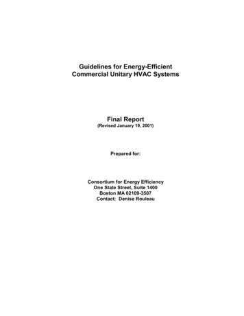
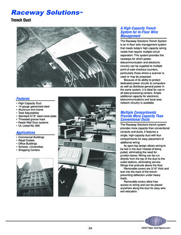
Raceway SolutionsTMTrench DuctA High-Capacity TrenchSystem for In-Floor WireManagementThe Raceway Solutions Trench Systemis an in-floor wire management systemthat meets today’s high-capacity wiringneeds that require multiple circuitseparation. This system provides theraceways for which power,telecommunication and electroniccircuitry can be supplied to multiplepoint-of-sale checkout counters,particularly those where a scanner isused or may be proposed.Because of its ability to protectdedicated power circuits to computersas well as distribute general power inthe same system, it is ideal for use inall data processing centers. Ampleadditional capacity for electronic,telecommunications and local areanetwork circuitry is available.Features High Capacity Duct14 gauge galvanized steelAluminum trim frameTotal AdjustabilityStandard 3/16" steel cover plateThreaded groove trackFeeds Wall Duct systemsUL Listed No. 884Multiple CompartmentsProvide More Capacity ThanConventional DuctsThe Raceway Solutions trench systemprovides more capacity than conventionalconduits and ducts. It features asingle, high-capacity duct with fourcompartments for easy placement ofadditional wiring.Its open-top design allows wiring tobe laid in the duct instead of beingpulled, eliminating the need forjunction boxes. Wiring can be rundirectly from the top of the duct to theoutlet stations, eliminating servicefittings that protrude above the floor.Removable covers are 3/16" thick andlock into the track of the trenchpreventing deflection under heavyloads.Removable covers allow freeaccess to wiring and can be placedanywhere along the duct for easy wireexit relocation.Applications Commercial BuildingsRetail OutletsOffice BuildingsSchools, UniversitiesShopping Centers24c2005 Filges www.filgesco.com
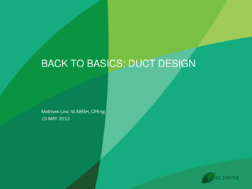
Raceway SolutionsTMTrench Duct The leveling screws provide verticaladjustment of the duct prior toconcrete pour; this allows the duct tobe leveled to the screed line so onlyone pour is requiredTileTrimThreadedGrooveDuct FrameDuct frame includes fixed metalpartitions that create multiplecompartments in the duct. This featurepermits a single duct to distributepower, electronics andcommunications. Duct with fewerpartitions is available to meet yourspecifications and can be located instrategic places to meet specialdistribution requirements.The duct frame is available in avariety of sizes. The frame is of 14gauge galvanized steel and issupplied in standard 6' lengths. It canbe cut to length which increases fieldflexibility and eliminates the need forordering specialty fabricated material. The aluminum tile trim provides afinished edge for the tile, assists incutting, and can be reversed whenthe trim is not required; can bereversed when carpet is used The extruded rubber gasket acts asa cushion, sound dampener andmoisture barrier between the coverplate and the duct; meets U.L.moptight requirementsDuct Support AssemblyThe unique duct support assemblyprovides one time leveling capabilityand acts as a splice for duct sections.The assembly consists of the levelingscrew clip, mounting plate, andleveling screws, and is independent ofthe final support of the duct.LevelingScrew ClipLevelingScrewPartitionTrackThe track of the structural assemblyintegrates the base aluminum profilewith the tile trim, extruded rubber strip,and the duct support assembly. Thetrack also provides the screed line forthe concrete. The aluminum profile accepts andholds the duct frame, rubbercushion, and cover plate screws inaddition to supporting the coverplate; it also acts as a runner for theleveling screw clips.MountingPlateCarpetTrimRubber StripAluminumProfileCoverThe cover plates for the RacewaySolutions Trench Duct are horizontallyadjustable to any point along the duct.The 3/16" thick cover plates come instandard 24" lengths — three areprovided per 6' duct section. A 1/4"thick cover plate is also available as acustomer option.A special threaded groove on thetrack accepts the cover plate screwsat any point along the duct, providingthe cover unlimited adjustment. Thisspecial design relieves the installerfrom matching the duct frame sectionswith the covers, eliminating fieldcutting in most instances. This cansubstantially reduce installation andmaintenance costs.The cable exit may be installed onan exit fitting cover allowing cable tobe easily pulled out and activated.The cable exit is reversible to provideaccessibility from either direction. Thestandard cover plates may beremoved and exit fitting coversinstalled for the cable exit.Leveling screw allows for 1" adjustment. The leveling screw clip integrateswith the track and provides fulladjustment along the length of theduct; it also acts as the splice forduct sections The heavy gauge mounting platefastens duct to metal deck,roughslab,or wood/metal forms prior topouring concrete; it adjusts to meetmost floor and installationrequirements.25c2005 Filges www.filgesco.com
Raceway SolutionsTMTrench DuctDuct SectionsCat.No.Raceway Solutions Trench Duct is manufactured in 6 foot lengths complete with three leveling feet on each side (OK/F-2-1/2), threecover plates 24" long (OKC) and three coverjoint protectors (OK/DSD). The leveling feet(screw clips) permit 1" of vertical adjustmentand act as section couplers. Additional verticaladjustment is available on order by increasingthe length of the screw in the OK/F.NOTE: All vertical adjustment should be madebefore the concrete is tment Area(sq.in.)ABCDCell Width(in.)BCADFour CompartmentOKA/B12-4C122½12⅞6.66.66.66.63.15 3.153.15 3.15Three �39⅞12⅞12⅞6.78.810.96.7 6.78.8 8.810.9 L Listing No. 884Catalog Number SystemOKA/B124C-AL1/4¼“ ThickCover PlateDepthTrench ProductOKA–TrenchOKB–Pull BoxOKC–Exit CoverOKE–End CapOKL–Horizontal LOKR–Vertical RiserOKT–”T” Junction BoxOKX–”X” Junction Box½” IncrementsA 2”B 2½”C 3”D 3½”E 4”Aluminum(optional)(optional)WidthJ 6”9, 12, 18, & 24StandardN 8”(Other Widths Available)Number of Compartments1C2C3C4C ther Depths AvailableNote: *Other depths and widths are available. Please consult factoryfor details. Also available in Aluminum.Horizontal L FittingCat.No.AssociatedTrenchOutside CoverDimensionNo.ofCompartmentsOKA/B9-3C12" x 12"3OKL/B12-4COKA/B12-4C15" x 15"4OKL/C12-3COKA/C12-3C15" x 15"3OKL/B12-3COKA/B12-3C15" x 15"3OKL/B9-3CManufactured with a single cover and matchingcompartments to form a 90 Horizontal L.Note: Table only an example of available sizes. Please refer to above for catalog numbersystem.26c2005 Filges www.filgesco.com
Raceway SolutionsTMTrench DuctSingle Level “T ” Junction FittingManufactured with internal partitionsand crossovers to isolate power renchOKT/B9-3C15" x 12"OKA/B9-3COKT/B12-4C18" x 15"OKA/B12-4COKT/B12-3C18" x 15"OKA/B12-3COKT/C12-3C18" x 15"OKA/C12-3CNote: Table only an example of available sizes. Please refer to page 26 for catalognumber system.Single Level “X ” Junction FittingManufactured with internal partitionsand crossovers to isolate power renchOKX/B9-3C15" x 15"OKA/B9-3COKX/B12-4C18" x 18"OKA/B12-4COKX/B12-3C18" x 18"OKA/B12-3COKX/C12-3C18" x 18"OKA/C12-3CEnd CapCat.No.WidthMaximumConduitDepthOKE/B910"1¼"2 "OKE/B1213"1¼"2 "OKE/C1213"2"3 "Fits over end of trench run to close trench andprevent foreign material from entering. Endcap may be drilled to accept conduit.27c2005 Filges www.filgesco.com
Raceway SolutionsTMTrench DuctExit CoversCat.No.Designed to provide exit and feed for RacewaySolutions Trench Duct trench. Conduit openingsare provided for power and communication exitor feed using conventional fittings or servicefittings. Cable exit cap (OKSK) is for communication cable only. Exit fittings cover may bespaced anywhere along the length ofthe trench. All exit fitting covers are 6" long.ConduitHole SizeTrenchWidthOKC/9-3/4A3 4 "9"OKC/12-3/4A3 4 "12"OKC/9-3/4C3 4 "9"OKC/12-3/4C3 4 "12"Note: Table only an example of available sizes. Please refer to page 26 for catalog numbersystem.Cable Exit CapCat. No.DescriptionOKSKCable Exit CapFits opening on Exit Cover. Provides outlet forcommunication cable. Debris barrier included.Cable Exit Cap constructed from die castaluminum. For use with Type A exit covers only.Trench to Wallduct AdapterCat. No.OWV/D12OWV/D18A11 "17 "Screws included.Material: 14 gauge pre-galvanized steel.UL Listing No. E11624528c2005 Filges www.filgesco.com
Raceway SolutionsTMTrench DuctVertical Riser FittingCat.No.Manufactured to mount on trench in place ofcover.Partitioned to separate cells andflanged to attach to pull box. Removable frontcover and top cover. Standard height abovefinish floor —12 inches. Standard depth Note: Table only an example of available sizes. Please refer to page 26 for catalog numbersystem.Pull BoxCat.No.Manufactured to attach to trench sectionreplacing end cap. Divided into compartmentas shown.Additional depth permits attachmentof larger conduit. Will accept up to 4" conduit.Box is field OKA/B12-3C6"12"12"OKB/C12-3COKA/C12-3C6"12"12"UL Listing No. 884Fastening AnglesAccessories to join trench sections for fieldfabrication of horizontal and verticalassemblies.Cat. No.DescriptionOK/VWIHorizontal AngleOK/VVWVertical Angle29c2005 Filges www.filgesco.com
Raceway SolutionsTMTrench Duct SpecificationsSpecificationsRaceway Solution Trench Duct has beendesigned to offer the most completein-floor wire management system forcomputer terminals. The particular usefor retail store checkout countersusing scanners has been selected forthis catalog. Its potential capacity,unlimited point-of-delivery, and wirecompartmentalization provide flexibilityfor current requirements as well asfuture needs.Raceway Solution Trench Duct maybe specified for stores that are beingretrofitted for the use of scanners aswell as new stores.The specifier should consider thefollowing:1. The two outer compartments forthe 12” size (2½" deep) have 6.6 in2wiring capacity. (This provides greatercapacity than 2½" conduit). Two powercompartments are offered: One for computer dedicated circuits One for general purpose powercomputer cables and the other forintercommunication or telephone.Depending on the sensitivity of thesystem, these two compartments maybe used interchangeably.4. Covers may be adjusted to anylocation as well as the exit fittingcovers. Therefore, predetermination ofexit locations is not required andfuture access to the wiring at anylocation is available.5. To feed the computer location orcheckout counter, service fittings withreceptacles may be used or the exitfitting cover hard wired to the point ofdelivery. For example, flexible metallicconduit or liquidtight conduit may beused between the exit fitting coverand a utility box with a receptacledirectly under the counter.6. Cable exit caps may be used forcomputer, telephone, or intercommunication cables. In certain cases,armored or other approved cable maybe permitted with the cable exit cap.2. The outer compartments shouldbe chosen for the power since runs ofconduit can be tapped off the sides ofthe duct (¾" and 1") to speciallyplaced floor boxes or stubbed out ofthe concrete to provide power atlocations to the left or right of thetrench.3. The inside compartments of thefour compartment 12" wide duct(OKA/B12-4C) each have 6.6 in2wiring capacity in a cross-sectionalarea that is 3.0" x 2¼" on sides. Thelargest electronic connector can passthrough this area and exit with ease.One of these can be designated for30c2005 Filges www.filgesco.com
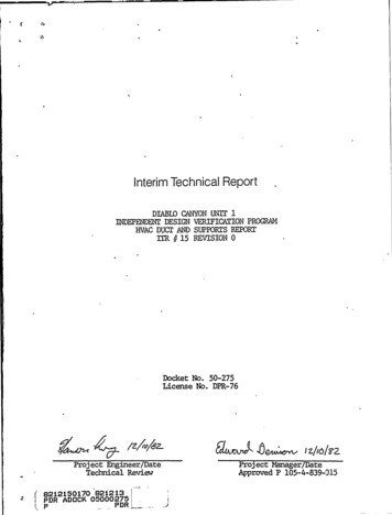
Raceway SolutionsTMTrench Duct Installation InstructionsA. First raceway. Circuiting within this raceway shall notoriginate or in any way be connected or routed throughdedicated panel.B Second raceway. All wiring within this raceway is exclusivelyfor the intra-store phone system only.C. Third raceway. All wiring within this raceway is exclusivelyfor the scanning communication cable.D. Fourth raceway. All circuiting within this raceway isdedicated for the scanner and must originate fromdedicated panel.Store Layout Example —Checkout CounterMaterialBefore Pour1.1 General inspection of shipment.1.1.1 Inspect all parts for visibledamage.1.1.2 Determine that the propernumber of parts were received. Notifyfactory immediately if a discrepancy isfound.1.1.3 If shop drawings were provided,installer must familiarize himself withall details.1.1.3.1 Installer must compare shopdrawings with actual jobsiteconditions.1.2 Inspection of Trench Components.1.2.1 Examine trench for propernumber and placement of partitions.1.2.2 If trench is factory marked,confirm markings.1.2.3 Do not remove covers fromtrench. Covers remain on trenchduring pour.2.1 General Jobsite Conditions.2.1.1 Determine a reference point forthe start of assembly work. Thisincludes an elevation mark as well ashorizontal placement. Confirm by shopdrawings when available.2.1.2 Clear the site of obstructions soinstaller has a clear working area.2.1.3 If installation is on grade,prepare the grade and checkspecifications for type of footing.Note: It is useful to install a rough slabthe length of the run. The slab shouldbe 24" wide and poured 2½" to 3½"below the finished floor screed. Thiswill assure fast installation and assureaccuracy of positioning.2.2 Installation Sequence of Trench.2.2.1 Position trench section beingcareful of location of the powercompartment. (See Store LayoutExample above.)312.2.2 Install and assemble duct totrench if required. (see Part 3.2.6)Refer to installation shop drawings.2.2.3 Couple trench sections. (SeePart 3.2).2.2.4 Carefully align the trench asshown on the plans.2.2.5 Fasten the support feet securelyto the concrete form, structure orgrade.2.2.6 Install end caps as required.c2005 Filges www.filgesco.com
Raceway SolutionsTMTrench Duct Installation InstructionsPart 3 —Assembly of Components3.1 General Assembly Requirements3.1.1 The power compartment oftrench must match and be as shownon the plans.3.1.2 Continuity of ground must beassured in all metal parts.3.2 Trench Components.3.2.1 Do not remove covers beforepour.3.2.2 Trench sections are coupledusing coupling clip furnished on thealuminum profile at the end of thetrench. Clip may be part of thesupport assembly.3.2.3 Check match of internal partitionbefore completing couple.3.2.4 Set screws on trench couplingclip must be tightened to assurecontinuity of ground.3.2.5 If rough slab is not available(see 2.1.3 Note) special care must betaken to assure support of mountingfeet and protect against movementduring pour.3.2.6 Junction fittings to adapt trenchto underfloor raceway do not requirerough slab (see 2.1.3 Note) but mustbe secure.3.2.7 Underfloor raceway requiresconcrete around supports (couplers)and under raceway.3.2.8 Tape underfloor raceway ifingress of concrete could occur.3.2.9 Field modification of trench.3.2.9.1 Where necessary trench canbe cut on the jobsite. For this purpose,bandsaws, hacksaws, or cuttingwheels can be used.3.2.9.2 When field cutting, do notremove cover to assure a properfinished joint.3.2.9.3 Horizontal Ell ’s or offsets maybe field fabricated by cutting equalangles from each of the pieces to bejoined.a. 45 cuts from axis of trench join tomake a 90 horizontal offset.b. 22½ cuts join to make a 45 horizontal offset.c. Partitions must match.d. Use OK/VWI to join pieces.3.2.9.4 A vertical Ell may be fieldfabricated using a section of trenchcut to desired height and OK/VVWfastening angles used to join sections.Part 4 —Securing,Elevating and LevelingSystem Prior to Pour4.1 General. The top of the systemmust be at screed level. Specificallythis includes the trench covers.4.1.1 When elevating and levelingsystem use laser level, electroniclevel, transit, conventional level, or anyapproved system.4.2 Leveling Trench.4.2.1 Turn leveling screws of thetrench support assembly to bring thecover of the trench to screed.4.2.2 Level the trench in one directionto prevent distortion of system.Part 5 —During and After Pour5.1 General Considerations5.1.1 Check installation for security,location and elevation.CAUTION: The covers of the systemserve as the screed line. They mustbe protected from accidentalmovement before and during pour.Correcting components for elevationafter concrete has set requiresextensive labor.5.1.2 If concrete mix is especially thin(fluid), gaps and openings in thesystem should be sealed with ducttape or other approved method.5.1.3 For aggregate greater than ¼inch, concrete flow aroundcomponents must be assured.5.2 Trench Components.5.2.1 Covers of trench serve as guidefor pouring concrete the level of thefinished floor.5.2.2 Concrete must be inserted undertrench by shovel or trowel.5.2.3 Hand screed to top of trench.5.2.4 The concrete must adhere tightlyto the trench edges.325.2.5 The covers of the trench must beexposed when the concrete floor isfinished.5.2.6 Remove sufficient covers toallow ventilation after concrete is set.Part 6 —Activation6.1 Activation Sequence.6.1.1 Correct any variation in concretepour along edges of trench.6.1.2 Remove covers from trench, andinspect installation.6.2 Activating Trench.6.2.1 Upon removing covers 6.1.2, laythe covers beside the trench in theirrelative position.6.2.2 Where exit fitting covers or othertrench exit fittings are required, laythem beside the trench in their relativeposition.6.2.3 If floor finish is not to beinterrupted by tile trim to establishcontinuity of floor cover, tile trim is toremain in shipping position. Do notelevate.6.2.4 Lay the required wiring in thetrench.6.2.5 Mount the exit fitting covers orother trench exit fittings on trench atproper location.6.2.6 Install cover joint protectors.OK/DSD.6.2.7 Install standard covers. Coversmay be adjusted or cut if required tocomplete enclosure.6.2.8 Remove cover adjacent to exitfittings to complete wiring.6.2.9 Lay floor covering. Take care toassure level floor over trench. Usefloor patch if necessary.6.2.9.1 If tile trim is used, adhesionbetween outer tile and tile trim mustbe assured and tile on coversaccurately positioned.c2005 Filges www.filgesco.com
Raceway SolutionsTMTrench Duct SpecificationsComponentsTrench Position Prior to Pour33c2005 Filges www.filgesco.com
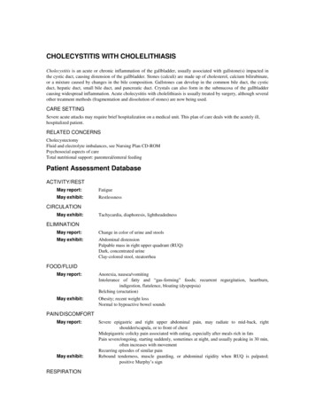
Raceway SolutionsTMTrench Duct Wirefill CapacityDimensions – Trench CConductor141210863.4 Sq.In.CompartmentTHW66534322165.0 04653652821337614121086Conductor141210865.4 Sq.In.CompartmentTHW104856936267.8 Sq.In.CompartmentConductor141210869.2 6Conductor141210863413.7 714610515.7 41168121XHHW41832825312087XHHW479376290137100c2005 Filges www.filgesco.com
Solutions Trench Duct trench. Conduit openings are provided for power and communication exit or feed using conventional fittings or service fittings. Cable exit cap (OKSK) is for communi-cation cable only. Exit fittings cover may be spaced anywhere along the length of the trench. All exit fitting covers are 6" long. Fits opening on Exit Cover.