Transcription
Quick Start Guide00825-0100-3511, Rev AAAugust 2020Rosemount CT5100 QSG ContinuousGas Analyzer
Quick Start GuideAugust 2020Safety precautionsImportantThe precautions in this manual MUST NOT be changed amended or removed. All authorized users,installation, operation and maintenance personnel, must observe the following safety precautions andwarnings.The Rosemount CT5100 analyzer is designed for use in Non Hazardous areas ONLY.WARNINGELECTRIC SHOCKThe analyzer operates using mains voltage, which may cause death or serious injury to personnel.Death, personal injury, and/or damage to persons and/or property may result if this is not observed.Confirm that the circuit breakers are set to OFF and locked out and tagged out before removing thetop cover or opening the front cover. The analyzer must be earthed.Only trained, qualified personnel may install and connect power and signal cables. The installation/connection must be in accordance with all legislative requirements and applicable standards.Only qualified personnel, familiar with potential risks, should install the analyzer.WARNINGFLAMMABLE SUBSTANCESSome parts of the analyzer may reach temperatures of 374 F (190 C) and may present an ignitionsource. The interior of a analyzer is always hot unless it has been switched off and allowed to cooldown. A fire may result if this precaution is not observed.Exercise care when using oil, paint, cleaning rags, or other flammable substances near the analyzer.WARNINGTRANSPORTATION HAZARDThe analyzer weighs 117 lb. (53 kg) and should always be lifted and moved using suitable lifting/moving equipment.Handle the analyzer with caution during unpacking, installation, maintenance, and transport toprevent crushing of hands, feet, or other body parts.Wear suitable protective gloves and protective footwear. When preparing the analyzer for transport byair, road, or rail, safeguard the analyzer against movement or break-away during transport by securelystrapping it in place.Use safety approved lifting equipment. Ensure that the equipment is tested, meets the lifting ratingsfor the weight of the equipment, and is in good operational condition.2Emerson.com/Rosemount
August 2020Quick Start GuideWARNINGFIRE AND EXPLOSIONFailure to observe this warning could cause an explosion or potentially hazardous situation, which if notavoided, may cause death, personal injury, and/or damage to persons and/or property.Always lock out the gas handling system when shutting down the analyzer.DO NOT operate the analyzer with doors or covers open.Refer to local regulations as this may require a competent hot work supervisor to issue a hot workpermit.When the analyzer is out of order all inputs and outputs connected to external equipment MUST beshut off.This will ensure that no hazardous voltages are present within the analyzer enclosure when notpressurized.Only properly trained personnel who understand the contents of all applicable manuals and relatedinstructions should start up the analyzer.Use only replacement parts and components authorized by Emerson.The analyzer contains a battery for data backup purposes.Under normal operating conditions, there is no need to replace the battery during the analyzer lifetime. Battery replacement MUST only be conducted by Rosemount Customer Care personnel. It is NOTa customer serviceable item.WARNINGFIRE, BURN, AND OPTICAL RADIATION EXPOSURE HAZARDElectrical shock, thermal burns, or loss of vision may occur. Failure to observe this warning could causean explosion or potentially hazardous situation, which if not avoided, may cause death, personal injury,and/or damage to persons and/or property.Operators and service personnel do not have access to the laser/electrics or upper cell compartmentsfor general maintenance or service.WARNINGBURNSSome parts of the analyzer may be heated to 374 F (190 C). To prevent burns, do not touch any of thehot parts.Before fitting, removing, or performing any maintenance on the analyzer, ensure that it has beenswitched off and allowed to cool for at least two hours. Before performing any maintenance on, or inthe vicinity of, the analysis cell, allow the analyzer to cool for at least 12 hours as the analysis cell isinsulated against heat loss.When handling the analyzer, always wear suitable protective gloves.If you receive a burn, seek medical treatment immediately.Quick Start Guide3
Quick Start GuideAugust 2020WARNINGHAZARDOUS SUBSTANCESFailure to observe this warning could cause a potentially hazardous situation, which if not avoided, maycause death, personal injury, and/or damage to persons and/or property.The analyzer may contain hazardous substances. Always handle the analyzer assemblies andcomponents with extreme caution. Wear personal protective equipment (PPE) when handling theequipment.Gas handling components within the analyzer contain particulate matter residue from the samplegases. Over the life of the the analyzer, the concentration of particulate matter will become enrichedwithin the gas handling components. When performing repairs and maintenance on the the analyzer:Handle used gas handling components with extreme caution.Avoid direct skin contact with used gas handling components.Do not smoke, drink, or eat in the work area.Wear goggles or eye shields.Wear a suitable face mask to protect against inhalation of particulate matter.Do not wet fingers, eyes, or any exposed skin.Pack used gas handling components for disposal in sealed packaging and label themContaminated.Dispose of contaminated items as hazardous material in accordance with applicable local,national, or international health and safety regulations and pollution regulations.Take special care to ensure that the sample gas return port either returns the sample gas to theproduct stream or discharges the sample gas to a location that will not cause a hazard.WARNINGOPTICAL RADIATION EXPOSURE HAZARDThere are three types of laser that may be included in the Rosemount CT5100: Quantum CascadeLasers (QCLs), Interband Cascade Lasers (ICLs), and diode lasers. The lasers within the analyzer areClass 1. The characteristics of the lasers contained within the analyzer are given in the table below.The emitted laser light is invisible (mid-infrared), and the combined laser powers are sufficiently low atthe first accessible aperture that the unprotected eye will not be damaged. This class is eye safe underall operating conditions.It is, however, possible to cause damage to the eye through not following correct procedures. Do notlook at the laser with any kind of magnifier or optical measuring device.ParameterQCLICLDiodeCommentOperation modePulsedPulsedPulsedN/ALasers per system1-61- 61- 6Maximum of 6 lasers per systemWavelength4 - 10 µm2 - 5 µmApproximately 760 nmN/APower 5 mW 5 mW 5 mWCombined power of QCL at firstaccessible aperture: 9.62 mWPulse duration 1 µs 1 µs 5 µsN/APulse repetitionfrequency 100 kHz 100 kHz 100 kHzN/ADuty cycle 5% 5% 25 %N/AThe combined power of the QCL, ICL, and diode lasers at the first accessible aperture is 9.62 mW.4Emerson.com/Rosemount
August 2020Quick Start GuideThe analyzer has warning labels in appropriate positions according to USA 21 CFR 1040.10.The use of controls or adjustments or performance of procedures other than those specified hereinmay result in hazardous radiation exposure.WARNINGHIGH PRESSURE GAS AND AIRThe calibration gas supply and compressed air supply operate at a pressure that can cause injury, e.g.,damage to eyes and skin punctures from debris blown by the high pressure gas or compressed air.Always lock off or tag out the calibration gas supply and compressed air supply when shutting downthe analyzer.The maximum gas pressure valve must not exceed 100 psig (690 kPa).WARNINGHAZARD BY WRONG INPUT VOLTAGEApplying a rated voltage other than specified on the analyzer s nameplate label may cause anexplosion, injury, or damage to the installation. Failure to observe this warning could cause anexplosion or potentially hazardous situation, which if not avoided, may cause death, personal injury,and/or damage to persons and/or property.This type of analyzer is always setup for a specific rated input voltage; see nameplate label.Ensure the voltage at site of installation meets the rated analyzer input voltage.WARNINGMAINTENANCE/MODIFICATIONSFailure to observe this warning could cause a potentially hazardous situation, which if not avoided,could result in death or serious injury.On completion of any maintenance and or modifications verify:All tools and equipment are removed.No contamination (water/dust) is in the compartments.Analyzer is wiped clean.Vents are clear and not obstructed.Verify that system is in a safe state for operation.WARNINGPhysical accessUnauthorized personnel may potentially cause significant damage to and/or misconfiguration of endusers’ equipment. This could be intentional or unintentional and needs to be protected against.Physical security is an important part of any security program and fundamental to protecting yoursystem. Restrict physical access by unauthorized personnel to protect end users’ assets. This is true forall systems used within the facility.Quick Start Guide5
Quick Start GuideAugust 2020CAUTIONEQUIPMENT DAMAGEFailure to perform pre-system start-up checks may cause damage to equipment.Do not power up or try to operate the analyzer unless it is physically secure and all electrical andpneumatic connections to the analyzer are in place.Before starting up the analyzer, ensure that electrical power, sample gas handling facilities, and anycalibration gases that are required are available to the analyzer.Always follow the Start-up procedure.Always follow the Shutdown procedure.CAUTIONUNSERVICEABLE EQUIPMENTIf the pressure and temperature screen does not display measurements similar to those shown inFigure 7-1 and Figure 7-2 .CAUTIONEMCThis is a Class A product. In a domestic environment, this product may cause radio interference, inwhich case the user may be required to take adequate measures.As a general principle, if any optical component other than the cell assembly, the laser modules, andthe detectors is unserviceable, the analyzer must be repaired by Emerson. This is because the repair,replacement, and alignment of the optical components requires the use of special optical test/calibration equipment and procedures.Some faults can only be repaired by Emerson. Where an item is unserviceable, and no replacementprocedure is given in this manual, then the fault must be repaired by Emerson.ContentsIntroduction. 7Description. 10Specifications.12Install. 18Controls and display controller. 32Start-up procedure.39Operating the analyzer.45Shutdown procedure. 47Engineering drawings.526Emerson.com/Rosemount
August 2020Quick Start Guide1Introduction1.1DescriptionThe Rosemount CT5100 Continuous Gas Analyzer, referred to hereafter asthe Rosemount CT5100, or analyzer, is an electronic sensor that uses laserspectroscopy to perform analysis of process gas streams.ImportantThe Rosemount CT5100 is designed for use in Non Hazardous areas ONLY.1.2Customer informationThis manual contains all the important information that must be followed toensure the correct operation and safety of personnel when operating theanalyzer.For information regarding installation, consult Install .Emerson is committed to continuously improving its products anddocumentation. Every effort will be made to include in the documentationany modifications by the manufacturer. However, this document reflects thesupplied analyzer at the revision date on the front cover.Should you require further information, or should particular problems arisethat are not covered in this manual, you can request additional help fromCascade Technical Support (cascade.support@emerson.com) or Emersondistribution partners. Further contact details for Emerson can be found onthe back page of this manual.1.3Safety precautions and conditions for safe useWARNINGSAFE USE PRECAUTIONSBefore installing or performing any maintenance on the analyzer, read andunderstand the safety information given in the preliminary information ofthis manual.The analyzer described in this document has been quality control tested andleft the manufacturer in pristine condition. To achieve the correct and safeoperation of this product, it must be transported, installed, operated, andmaintained as described by the manufacturer.All lasers used within the analyzer are Class 1. The emitted laser light isinvisible (mid-infrared) and the pulse duration so short that the unprotectedeye will not be damaged.Quick Start Guide7
Quick Start GuideAugust 2020The nature of the laser beam path and beam width further ensures that itshould be impossible to cause any eye damage. The analyzer has warninglabels at appropriate positions in accordance with USA 21 CFR 1040.10.General safety notice/residual riskInstallation, operation, and maintenance of the analyzer must be inaccordance with these instructions.When operated as intended and all applicable safety instructions areobserved, an element of risk will remain, including, but not limited to, thefollowing: The emission of gases hazardous to health may be possible when all gasconnections have been correctly made. To avoid exposure to the dangers of residual risks, take particular carewhen installing, operating, maintaining, and servicing the analyzer.1.4Qualified personnelIn-depth specialist knowledge is an absolute requirement for working withand on the analyzer. Personnel installing, operating, servicing, andmaintaining the analyzer must be instructed, trained, qualified, andauthorized personnel of the operating company for hazardous areas and themanufacturer.It is the operating company's responsibility to: Train staff Observe safety regulations Follow the safety instructions and procedures in the product manualOperators must: Be trained Read and understand all relevant sections of the product manual beforecommencing work Know the safety mechanisms and regulationsWARNINGTo avoid explosions, loss of life, personal injury, and damage to thisequipment and on-site property, do not install, operate, maintain, or servicethis analyzer before reading and understanding this reference manual andreceiving appropriate training.8Emerson.com/Rosemount
August 20201.5Quick Start GuideSoftware versionThe analyzer includes software that is used to control the operation of theanalyzer. This document describes the software version as: 5.7.13.Quick Start Guide9
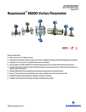
Quick Start GuideAugust 20202Description2.1System overviewA complete Rosemount CT5100 system consists of the analyzer, and theassociated interconnecting wiring and gas piping.The customer MUST provide the gas handling system and interconnectingwiring and gas piping.The circuit breaker used to control the application of electrical power to theanalyzer, the interconnecting wires, and gas piping are provided by thecustomer.In Figure 2-1, the items supplied by Emerson are colored blue; the itemssupplied by the customer are colored purple. The green gas handling systemmay be provided by Emerson or the customer.Figure 2-1: Rosemount CT5100 InstallationA.B.C.D.E.F.G.H.Gas handling systemSample supply lineSample return (exhaust) lineRosemount CT5100Electrical powerTwo pole main isolator complete with RCDControl centerMeasurement dataThe analyzer contains an optical system with multiple lasers and a series ofoptical components that provide an optical path, a heated multi-passanalysis cell, and sample inlet and outlet ports that can be connected to agas handling system and control and analysis electronics. The number of10Emerson.com/Rosemount
August 2020Quick Start Guidelasers installed depends upon customer requirements. The complete systemoperates at either 110 or 240 Vac 50/60 Hz supply.Quick Start Guide11
Quick Start GuideAugust 20203Specifications3.1Detailed system specificationsTable 3-1 gives the physical characteristics of the analyzer. Schematicdiagrams of the sensor and mounting points are shown in Figure 3-1 andFigure 3-2. Table 3-2 gives the general characteristics of the analyzer.Table 3-1: Physical CharacteristicsRosemount CT5100ValueCommentExternal dimensions22.64 x 11.73 x 28.11 in.575 x 298 x 714 mmLength x width x heightNominal dimensionsWeight117 lb.53 kgApproximate weightTable 3-2: General CharacteristicsRosemount CT5100ValueUnitsCommentInstrument supply voltage110 to 240Vac50/60 HZ 10%Peak power consumption500WMax consumption pergas analyzerContinuous steady-statepower consumption300WOnce the gas analyzerhas stabilized and theanalysis cell has reachedthe temperature setpointElectrical compartmentenclosureN/AN/A304 stainless steelOptical compartmentenclosureN/AN/APolyester TGIC freepowder coated 304stainless steelWetted materialsN/AN/AAISI 316 (EN 1.4401grade) stainless steeltubing and fittingsincluding thermowelland pressure diaphragm,PFA coated aluminumcell body, PTFE seals,protected gold coatedmirrors, CaF2 windows,and FKM (typicallyViton ) or FFKM(typically Kalrez ) Orings12Emerson.com/Rosemount
August 2020Quick Start GuideTable 3-2: General Characteristics (continued)Rosemount CT5100ValueUnitsCommentMeasurement techniqueN/AN/AMid infrared (IR)absorption spectroscopyMid IR sourceN/AN/AQuantum Cascade LaserNear IR sourceInterband Cascade LaserDiode LaserLaser classificationClass 1Inlet gas port connector¼6in.mmSwagelok type, factoryconfigured, specify onorderOutlet (exhaust) gas portconnector¼6in.mmSwagelok type, factoryconfigured, specify onorderMeasurement result signals4 to 20mA4 or 8 channel outputs,specify on orderCommunication10/100MbpsEthernetWarm-up time90minutesN/AQuick Start GuideBS EN 60825-1: 2007safety of laser products.Equipment classificationand requirements(identical to IEC 60825-12007)13
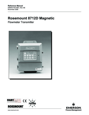
Quick Start GuideAugust 2020Figure 3-1: Rosemount CT5100 Dimensions - Front ViewDimensions are in inches (mm).A. Lifting eyeletB. VentilationC. User interface14Emerson.com/Rosemount
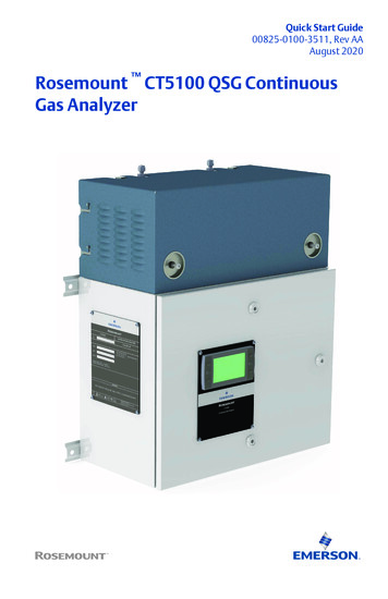
August 2020Quick Start GuideFigure 3-2: Rosemount CT5100 Dimensions - Top ViewDimensions are in inches (mm).A. Lifting eyeletB. Sample returnC. Sample inletQuick Start Guide15
Quick Start GuideAugust 2020Figure 3-3: Rosemount CT5100 Dimensions - Bottom ViewDimensions are in inches (mm).A. Cable glandsB. Earth pointTable 3-3: Environmental tsCommentOperating temperaturerange-4 to 131-20 to 55 F CAmbient temperatureSample gas temperaturerange131 to 37450 to 190 F CFactory set, specify onorderSample gas particulatedensity5mg/m3MaximumµmMaximumSample gas particulate size 1016Emerson.com/Rosemount
August 2020Quick Start GuideTable 3-3: Environmental Characteristics mmentIP codeIP66 (electricalcompartmentenclosure)IP20 (opticalcompartmentenclosure)N/AIP to IEC 60529Sensor humidity range10 to 95%Relative humidity (noncondensing) at 113 F (45 C)Quick Start Guide17
Quick Start Guide4Install4.1Site selectionAugust 2020The Rosemount CT5100 has a T3 temperature classification which specifiesthe maximum surface temperature of the analyzer.WARNINGFIRE AND EXPLOSIONDeath, personal injury, and/or damage to persons and/or property mayresult if this is not observed.The analyzer's electrical compartment must not be opened unless theatmosphere in the area is known to be below the ignitable concentration ofcombustible gases or materials, or unless all equipment within the protectedenclosure is de-energized.WARNINGELECTRIC SHOCKThe analyzer operates using mains voltage, which may cause death orserious injury to personnel. Failure to observe this precaution will causedeath, personal injury, and/or damage to persons and/or property.Ensure that the circuit breakers are set to Off and locked out and tagged outoff before removing the top cover or opening the front cover.The analyzer is intended to be installed in a suitable Division 2 shelter toprotect it from the elements.Provide sufficient space around the analyzer to allow the maintenance andservicing of the unit.18Emerson.com/Rosemount
August 20204.2Quick Start GuideUnpackingThis procedure requires a minimum of two people to safely remove theequipment from the shipping container.WARNINGHEAVY INSTRUMENT - LIFTING HAZARDHandle the analyzer with caution during unpacking, installation,maintenance, and transport to prevent crushing of hands, feet, or otherbody parts.The analyzer weighs and should always be lifted and moved using suitablelifting/moving equipment. Emerson recommends that a minimum of twopeople using suitable tools for transportation and lifting are employed.Wear suitable protective gloves and protective footwear.CAUTIONEQUIPMENT DAMAGEFailure to observe this caution may cause damage to the equipment.When preparing the analyzer for transport by air, road, or rail, safeguard theanalyzer against movement or break-away during transport by securelystrapping it in place.WARNINGEXPLOSION HAZARDInstalling and wiring the analyzer must comply with all relevant nationallegislative requirements and regulations.Consider all safety instructions within this manual and all associated analyzerinstruction manuals.WARNINGEXPLOSION HAZARDInstalling the analyzer requires opening the enclosure and working at theopen unit. This is permitted only when both the analyzer and connectedexternal circuitry are de-energized.Depending on the local regulation, this may require a competent hot worksupervisor to issue a hot work permit.Quick Start Guide19
Quick Start GuideAugust 2020WARNINGHEAVY ITEMFailure to propery handle the analyzer may cause injury to personnel.Ensure the wall the analyzer is mounted on is solid, stable, and of suitablematerial to hold the weight of the analyzer.Handle the analyzer with caution during unpacking, installing,maintaining, and transporting to prevent crushing of hands, feet, orother body parts.Emerson recommends that a minimum of two people move and lift theanalyzer.Wear suitable protective gloves and protective footwear.CAUTIONSHOCK AND VIBRATIONDamage to the analyzer may result from a failure to follow this caution.The analyzer contains sensitive electronic equipment. It MUST NOT besubjected to any shock and or vibration.Procedure1. On receipt of goods, look for any visible damage to the analyzer andverify that all items shipped were received. Record on the goodsreceipt note any damage or missing items, noting both the item(s)and quantity missing.2. Visually inspect the exterior of the analyzer for signs of damage,corrosion, gas leaks, or signs of previously overheating.3. Report anything found to the maintenance organization.4. Attach suitably rated and tested lifting slings to the safetyengineered lifting eye bolts mounted on top of the analyzer.5. One person should carefully guide the equipment from thehorizontal to vertical position while the other person lifts theequipment.6. Use safety approved and tested lifting equipment to remove theanalyzer from the shipping container and place it on a solid, levelsurface.7. Ensure that the analyzer is stored in its protective plastic cover untilinstallation.20Emerson.com/Rosemount
August 20204.3Quick Start GuideMounting the analyzerThis procedure requires two people to safely move and mount theRosemount CT5100.Procedure1. Ensure that there is free space around the analyzer to allowventilation of the upper part of the analyzer.WARNINGHEAVY ITEMFailure to propery handle the analyzer may cause injury to personnel.Ensure the wall the analyzer is mounted on is solid, stable, and ofsuitable material to hold the weight of the analyzer.Handle the analyzer with caution during unpacking, installing,maintaining, and transporting to prevent crushing of hands, feet, orother body parts.The analyzer weighs 117 lb. (53 kg).Emerson recommends that a minimum of two people move and liftthe analyzer.Wear suitable protective gloves and protective footwear.Quick Start Guide21
Quick Start GuideAugust 20202. Attach suitably rated and testing lifting slings to the safetyengineered lifting eye bolts mounted on top of the analyzer.Figure 4-1: Front View DimensionsDimensions are in inches (mm).A.B.C.D.E.Lifting eye boltSample gas input portSample gas return portLifting eye bolt0.413-in. (10.5 mm) diameter mounting bolts3. One person should carefully guide the equipment while the otherperson operates the lifting equipment.22Emerson.com/Rosemount
August 2020Quick Start Guide4. Use safety approved and tested lifting equipment to lift the analyzerfrom the stable platform.5. Ensure that the wall fixing points are capable of supporting a load of242 lb (110 kg) each; this includes a x 2 factor of safety. Figure 4-2shows the locations of the mounting points on the analyzer.6. Mount the analyzer using four M8 (⅜-in.) fasteners to attach to thewall. Do not overtighten the fasteners.The bolts must be positioned in such a way to allow maximum use ofall the thread length.7. Remove the lifting eyes and retain them for future use.Threads must be protected with a suitable grease and plasticgrommets.Figure 4-2: Mounting DetailsDimensions are in inches (mm).A. Mounting pointsQuick Start Guide23
Quick Start GuideAugust 2020Figure 4-3: Clearance with Door OpenDimensions are in inches (mm).A. Door openB. Door closedC. Door opening arcPostrequisitesAfter mounting, do not place any additional load on the analyzer. or leaveany loose items on flat surfaces.4.4Connecting the electrical/electronic inputs and outputs4.4.1AC powerPower is connected to the analyzer instrumentation through the powerentry point fitted to the base of the analyzer. Refer to Figure 4-4.24Emerson.com/Rosemount
August 2020Quick Start GuideFigure 4-4: Power GlandA. Power and signal/exit pointsB. M6 earth studThe customer supplied circuit breaker, complete with RCD, MUST be inaccordance with local and national standards.Quick Start Guide25
Quick Start GuideAugust 2020Figure 4-5: Power Entry Point ConnectionsA. To mains input fusesB. Mains input filterC. To enclosure earth studTable 4-1: Mains Input Terminals User ConnectionsTerminalFunction1Sensor system supply (L)2Sensor system supply (N)3Earth (E)Electrical protection for the instrumentation circuitry of the analyzer isprovided by fuses F1 and F2 located inside the analyzer. Refer to Figure 4-6.The customer supplied power cable for the analyzer instrumentation will beconnected to terminals 1 - 3.26Emerson.com/Rosemount
August 2020Quick Start GuideTable 4-2: Electrical Power RequirementsElectrical pply voltage500 W100 to 230 Vac, 50/60 Hz 10%3.15 AinternalfusesF1 and F2For the electrical power wiring use 16 AWG stranded, three conductorcopper or tin-plated copper power wire, rated for at least 250 Vac, of therequired length. Cables must be terminated in the power entry points inaccordance with local and national electrical codes. The full electrical wiringdiagram is provided in Engineering drawings.4.4.2FusesFigure 4-6 shows the location of the fuses.Figure 4-6: FusesA.B.C.D.E.Quick Start GuideFuse F4 (24 Vdc supply)Fuse F3 (12 Vdc supply)Fuse F1 (mains supply – live)Fuse F2 (mains supply – neutral)Industrial power supply27
Quick Start GuideAugust 2020Table 4-3: Fuse Requirements4.4.3FuseFunctionRatingSchurter partnumber1Live line 110/240Vac (followingmains filter)3.15 A, 240 V, fastacting ceramic0001.10092Neutral line110/240 Vac(following mainsfilter)3.15 A, 240 V, fastacting ceramic0001.10093Analyzer 12 Vdcsupply rail3.15 A, 240 V, fastacting ceramic0001.10094Analyzer 24 Vdcsupply rail3.15 A, 240 V, fastacting ceramic0001.1009Connecting the sample supply and return lineSample gas supply and sample return connections are ¼-in. (6mm) ”Hamlet” compression tube fittings. To avoid the risk of gas leaks,confirm that these connections are made correctly and tightly. Both thesample gas supply pipe and the sample return pipe should be thermalinsulated.The maximum sample gas supply pressure is 2 BarG.4.4.4Connecting the signal cablesThe signal cables are connected to the system through conduit outlets (Band C as shown in Figure 1). All signal cables are to be minimum 20 AWG trirated switchgear cable. Customer supplied conduit and cables are to beterminated in the conduit outlets in accordance with local and nationalelectrical codes.28Emerson.com/Rosemount
August 2020Quick Start GuideFigure 4-7: Signal Cable OutputsA.B.C.D.E.F.G.H.I.J.K.L.To mains input fusesMains input filterTo enclosure earth studTo digital modulesTo digital modulesTo analog modulesTo status relaysDigital output terminalsAnalog or digital output terminalsAnalog output terminalsStatus output terminalsMains input terminalsTable 4-4: System WiringTerminalFunction1Sensor system supply (L)2Sensor system supply (N)3Earth11Digital output 112Digital outp
Parameter QCL ICL Diode Comment Operation mode Pulsed Pulsed Pulsed N/A Lasers per system 1 - 6 1- 6 1- 6 Maximum of 6 lasers per system Wavelength 4 - 10 µm 2 - 5 µm Approximately 760 nm N/A . Always lock off or tag out the calibration gas supply and compressed air supply when shutting down the analyzer. The maximum gas pressure valve must .